Simultaneous usage of the LHCb HLT farm for
Online and Offline processing workflows
Joel Closier1,*, Clara Gaspar1, Luis Granado Cardoso1,** , Christophe Haen1,*** , Beat Jost1
and Niko Neufeld1, on behalf of the LHCb Collaboration.
1CERN, European Organization for Nuclear Research, Geneva, Switzerland
Abstract. LHCb is one of the 4 LHC experiments and continues to revolutionise data acquisition and analysis techniques. Already two years ago the concepts of “online” and “offline” analysis were unified: the calibration and alignment processes take place automatically in real time and are used in the triggering process such that Online data are immediately available offline for physics analysis (Turbo analysis), the computing capacity of the HLT farm has been used simultaneously for different workflows : synchronous first level trigger, asynchronous second level trigger, and Monte-Carlo simulation. Thanks to the same software environment, LHCb can switch seamlessly and fast from Online to Offline workflows, run them simultaneously and thus maximize the usage of the HLT farm computing resources.
1 Introduction
LHCb [1] is one of the 4 LHC experiment at CERN and which has been active for 10 years. The data taken by the detector are processed by a set of computers in real time to decrease the amount of information that will be stored on tape for analysis purpose afterwards by physics community.
The computing capacity is quite important and LHCb has decided to use this capacity during idle cycle to process some Monte Carlo generations. In this paper, we will describe the environment of the High Level Trigger (HLT) farm, the various workflows that we use and how we are able to have this concept of “online” and “offline” analysis unified.
2 HLT farm environment
The HLT farm is composed of around 1500 PCs, distributed over 60 subfarms. The subfarms are logically divided in the control system and each subfarm row is composed with 24, 28 or 32 PCs each. Each of the subfarms is controlled by a controller PC. These controller nodes
* Joel Closier: [email protected]
are also connected to a top level HLT control node, which manages the availability and allocation of the subfarms for the global Experiment Control System (ECS).
This number of computers represents roughly 12 000 cores that are idle when there is no data-taking.
2.1 Control system ECS
The Experiment Control System (ECS) [2] in LHCb is based on the SCADA WinCC OA (see next section) with custom LHCb developed components. This application installed on the controller PC managed the HLT tasks on the HLT nodes.
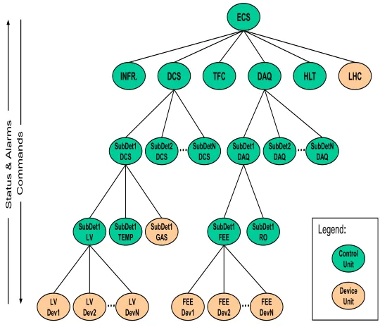
ECS controls the whole experiment as shown in Figure 1 in particular:
• Front end electronics
• High Level Trigger (HLT) • Data Acquisition System (DAQ)
Figure 1. Experiment Control System overview.
ECS is able to configure the whole experiment based on the different states of the LHC accelerator. In the future, we also want to integrate the configuration of the production tools for offline activities (DIRAC tasks) in ECS.
2.2 WINCC OA
The SCADA WinCC OA is a commercial product from Siemens. It is used throughout CERN and provides, amongst other things, the user interfaces, the archiving interface and the general alarms for the ECS.
LV
Dev1 Dev2LV DevNLV
DCS SubDetN DCS SubDet2 DCS SubDet1 DCS SubDet1
LV SubDet1TEMP SubDet1GAS
…
…
C om m ands DAQ SubDetN DAQ SubDet2 DAQ SubDet1 DAQ SubDet1 FEE SubDet1ROFEE
Dev1 Dev2FEE DevNFEE
Control Unit Device Unit
…
…
Legend:INFR. TFC LHC
are also connected to a top level HLT control node, which manages the availability and allocation of the subfarms for the global Experiment Control System (ECS).
This number of computers represents roughly 12 000 cores that are idle when there is no data-taking.
2.1 Control system ECS
The Experiment Control System (ECS) [2] in LHCb is based on the SCADA WinCC OA (see next section) with custom LHCb developed components. This application installed on the controller PC managed the HLT tasks on the HLT nodes.
ECS controls the whole experiment as shown in Figure 1 in particular:
• Front end electronics
• High Level Trigger (HLT) • Data Acquisition System (DAQ)
Figure 1. Experiment Control System overview.
ECS is able to configure the whole experiment based on the different states of the LHC accelerator. In the future, we also want to integrate the configuration of the production tools for offline activities (DIRAC tasks) in ECS.
2.2 WINCC OA
The SCADA WinCC OA is a commercial product from Siemens. It is used throughout CERN and provides, amongst other things, the user interfaces, the archiving interface and the general alarms for the ECS.
LV
Dev1 Dev2LV DevNLV DCS SubDetN DCS SubDet2 DCS SubDet1 DCS SubDet1
LV SubDet1TEMP SubDet1GAS
…
…
C om m ands DAQ SubDetN DAQ SubDet2 DAQ SubDet1 DAQ SubDet1 FEE SubDet1ROFEE
Dev1 Dev2FEE DevNFEE
Control Unit Device Unit
…
…
Legend:INFR. TFC LHC
ECS HLT St at us & Alarm s
A control system based on WinCC OA was developed to manage the processing of the offline data on the HLT farm. It is able to monitor and control all the worker nodes on the HLT farm which are organized topographically with farms and subfarms as explained previously. Each worker node can adopt independent configuration and some of the settings that can be used are:
• Set the exact number of jobs on each machine
• Possibility to set automatically the number of jobs depending on the machine CPU
• In case of automatic configuration, possibility to set the number of cores to be left unused (for DIRAC)
With this configuration, there is no need to change the settings of each node to switch between task and we can easily use just a part of the farm in case some nodes are needed for data taking or for test purposes.
2.3 DIRAC
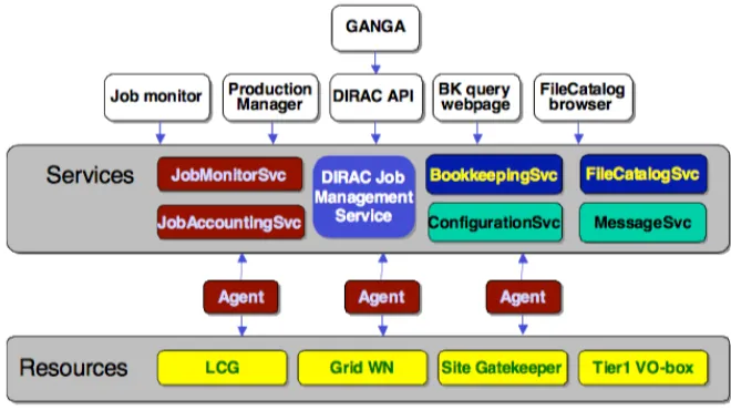
DIRAC [3] (Distributed Infrastructure with Remote Agent Control) INTERWARE (Figure 2) is a software framework for distributed computing providing a complete solution to one (or more) user community requiring access to distributed resources. DIRAC builds a layer between the users and the resources offering a common interface to a number of heterogeneous providers, integrating them in a seamless manner, providing interoperability, at the same time as an optimized, transparent and reliable usage of the resources.
Figure 2. DIRAC Overview of the architecture.
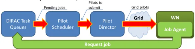
A DIRAC script is a task started on each worker node which perform some actions to run the workflow shown in Figure 3.
• Sets the proper computing environment
• Launches the agent which will also do several actions:
§ Execute in the local disk where the input data, if any, will be
downloaded and where the output will be written
§ At the end of the task, upload the output to the storage located in
the computer centre
• During the execution of the task, information is sent to DIRAC monitoring to follow the progress of the job
Figure 3. Standard DIRAC job submission cycle.
2.4 LHCb software environment
LHCb is using the CernVM File System (CVMFS) to distribute all the LHCb applications. CVMFS is mounted on all the computer centres that are providing computing resources for LHCb: Tier0, Tier1, Tier2 and the HLT.
To run the LHCb applications, we set an environment which is also based on the CernVM File System. The facility to have the same environment eases the initialisation phase of any activities on our computing resources.
3 LHCb workflows
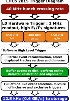
In the HLT farm, the resources are used for three main type of activities (Figure 4) that we will describe in the following sections.
Figure 4. LHCb 2015 Trigger Diagram.
3.1 High Level Trigger 1
The first workflow which is used, is the High Level Trigger 1 (HLT1) which reduces the data taking rate from 1 MHz to 100 kHz. This workflow is run synchronously in real time.
3.2 High Level Trigger 2
The High Level Trigger 2 (HLT2) is run asynchronously on the HLT1 output which has been buffered on the local disk of the HLT farm worker nodes and reduces the rate to 12 kHz. This workflow is completely software based and runs on a dedicated computing farm with around 1500 PCs, which represents, roughly 50 000 Hyper Core. The HLT2 software is installed on CVMFS on all the worker nodes.
3.3 Monte Carlo simulation
The HLT farm is also used during idle cycle to run DIRAC jobs which will simulate events. The simulation software is installed on CVMFS and the environment is set in the same way as the HLT2 software. This eases the usage of the farm for these two different workflows.
4 HLT farm usage
Figure 5. HLT farm activity during data taking start-up period.
The simulation application, based on Gaudi, has been instrumented to catch an interrupt signal. We can see in Figure 6, that when we need to free the HLT farm for data taking, the control system can send an interrupt signal to all the tasks running in the worker nodes and in few minutes, the tasks terminate gracefully without losing any processed events.
Figure 6. Switch activity in the HLT farm.
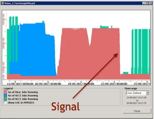
The facility to run simulation jobs on the HLT farm provides a big amount of resources to the simulation production. In Figure 7, we can see that CPU cycles used for the simulation production on the HLT farm is bigger than on any other Tier1 used by LHCb in the Grid. In addition, we can see in Figure 8 that the number of running jobs during the period without any data taking put in evidence the benefit of the resources provided by the farm.
Figure 7. HLT farm CPU days.
Figure 8. HLT farm usage for 11 weeks.
5 Conclusion
References
1. The LHCb Collaboration, J. Instrum. 3 S08005 (2008)