1670 | P a g e
A Fast Integral Image Computing Methods: A Review
Km. Shivani
Design Engineer, Associated Electronics Research
Foundation, C-53, Phase-II, Noida (India)
ABSTRACT
Integral image computing is an important part of many vision applications and is characterized by concentrated
computation and frequent memory accessing. This brief proposes an approach for fast integral image
computing with high area and power efficiency for vision applications in embedded systems. For the data flow
of the integral image computation a dual-direction data-oriented integral image computing mechanism is
proposed to improve the processing efficiency, and then a pipelined parallel architecture is designed to support
this mechanism. The parallelism and time complexity of the approach are analysed and the hardware
implementation cost of the proposed architecture is also presented. Compared with the state-of-the-art methods
this architecture achieves the highest processing speed with comparatively low logic resources and power
consumption. And according to review we can improve the high area and power efficiency.
Keywords - Integral Image, Parallel Processing, Pipelined Architecture.
I. INTRODUCTION
Integral image computing is a very important and convenient method to accelerate the feature computation in the vision algorithms.The Integral Image or Summed Area Table, was first introduced to us in 1984, but wasn’t
properly introduced to the world of Computer Vision till 2001 by Viola and Jones with the Framework. The
Integral Image is used as a quick and effective way of calculating the sum of values (pixel values) in a given
image – or a rectangular subset of a grid (the given image).It can also, or is mainly, used for calculating the
average intensity within a given image. If one wants to use the Integral Image, it is normally a wise idea to make
sure the image is in greyscale first.
It can be used to compute the Haar-like feature in the Adaptive Boosting (AdaBoost)-based face detection [1],
[2], speech detection, and human activity recognition [3], and can also be used to compute the Speeded Up
Robust Features in the corresponding detection occasions [4]. Although the integral image is an effective way to
quickly compute the features, the computing of integral image is computation and memory accessing intensive,
and usually accounts for large parts of the total execution time. In embedded vision applications such as object
detection in automotive systems, biomedical systems, and some portable systems, real-time processing is
required within a limited power budget and hardware implementation size. Since specialized hardware
consumes less power and can be built into small systems, it is more suitable for embedded applications. Thus,
the implementation of fast integral image computing on specialized hardware is of vital practical significance.
1671 | P a g e
efficiency, such as the Kyrkou’s and Hiromoto’s methods [5] and [6]. However, the existing approacheshavesome drawbacks since the parallelism of the integralimage computing is not fully exploited during
computation. A faster speed of computation could be achieved with comparatively low power and in a small
area by fully exploiting the parallelism in the computation. In this brief, we propose a dual-direction
data-oriented integral image computing method to exploit the parallelism, and we design a parallel hardware
architecture based on the proposed method.
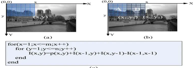
Fig. 1. Integral image computation. (a) Integral image definition. (b) A property of integral image. (c) Pseudo-code of integral image computing code.
To evaluate the proposed architecture, we implement the integral image computing methods in [5] and [6] on
hardware for comparison. The performance metrics, including speed, area, and power, are evaluated to show the
efficiency of the architecture.
II. INTEGRAL IMAGE COMPUTATION
Integral image, which is known as the summed area table, is a data structure that can quickly and efficiently
computethe sum of values in a rectangular subset of a grid [7]. The integral image value I(x, y) at location (x, y),
which is defined in following, is equal to the sum of the intensity of all pixels above and to the left of location
(x, y) in the original image p(x, y), as shown in Fig. 1(a):
Given an m × n image, the integral image value I(x, y) can be computed according to the pseudocode shown in
Fig. 1(c),where I(x, y) depends on I(x − 1, y), I(x, y − 1), and I(x − 1, y − 1). The integral image has a property
that we can makeuse of in hardware design [see Fig. 1(b)]. The integral imagevalue at (x0, y0) is the sum of the
intensity of all the pixels inarea A plus the sum of intensity of pixels in area B, which isshown in (2). Since the
1672 | P a g e
Hence, when the integral image of A is computed, if we want to compute the integral image values in B, we canregard B as an independent image and compute its integral image; then, we add each row of integral values with
the rightmost value at the same row in the integral image of A. Therefore, we only need to know the value of the
rightmost column in the integral image of A to compute the integral image value of B.
Fig. 2. Affine transformation of nested loop for integral image computing (a) Dependency graph of original loop. (b) Dependency graph of transformed loop.
1673 | P a g e
III. PENG OUYANG PROPOSED METHOD
In order to exploit the parallelism for hardware design, we need to analyse the data dependence of integral
image computing. The loop dependence graph of Fig. 1(c) is shown in Fig. 2(a). Each iteration I(x, y) = p(x, y) +
I(x − 1, y) + I(x, y − 1) − I(x − 1, y − 1) is represented by one small circle, and it depends on the prior iterations.
For example, the iteration I(x, y) depends on the iterations I(x, y − 1), I(x −1, y − 1), and I(x − 1, y). To achieve
the maximal parallelism, we use affine loop transformation to transform the original loop to a new form, which
is shown in Fig. 2(b), and we can find that the maximal parallelism is m as the iterations in the red circle have no
dependence between each other and can be processed in parallel.
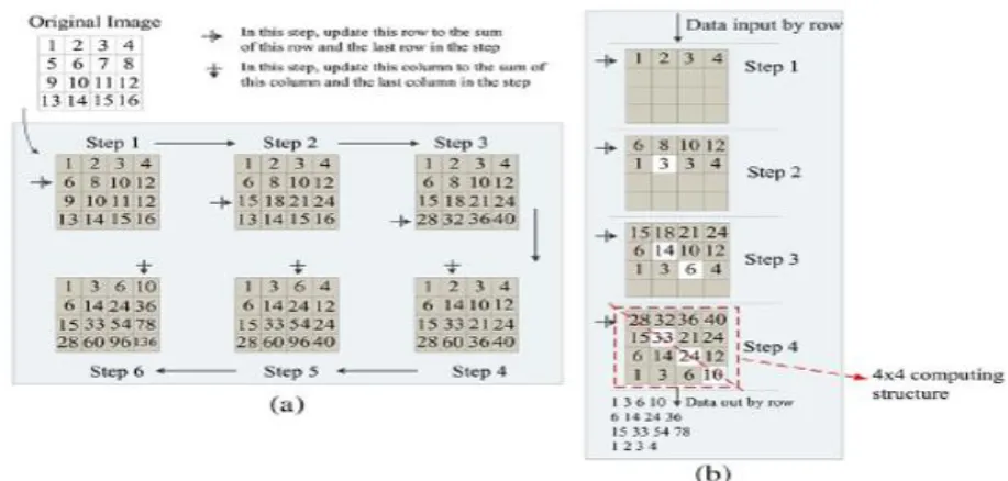
Hence, we propose a dual-direction (row direction and column direction) data-oriented method to exploit this
parallelism. As shown in Fig. 3(a), we use a 4 × 4 image to illustrate
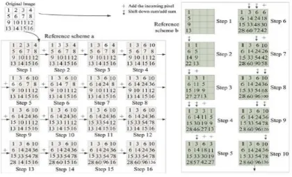
Fig. 4. Two reference integral computing schemes.
this method. Only six steps are used to compute the integral image. According to this method, for an m × n
image, we need n − 1 row operations and m − 1 column operations to compute its integral image; thus, m + n −
2 steps in total are needed, and the time complexity is O(m + n), which is much lower than the time complexity
of the conventional full accumulation algorithm (O(mn)). In Fig. 4, we adopt two related methods for
comparison. The reference scheme a denote Hiromoto’s integral image computing method in [6], and the
reference scheme b denotes Kyrkou’s integral image computing method in [5]. Hiromoto’s method is similar
with the full accumulation algorithm and needs 16 steps with time complexity of O(mn). In Kyrkou’s method,
the operations include adding the incoming pixels into the stored sum, propagating the incoming pixel to the
1674 | P a g e
complexity of O(2m + n). Our method shows the obvious advantage over these two methods. Further, to fullyexploit the parallelism, a pipelined structure can be designed as shown in Fig. 3(b), where the image is accessed
row by row, reducing further time complexity to O(n). This reduction is done by adding the incoming row of
pixels to update the current row of pixels in each cycle, and column operations can be achieved using cascaded
row registers and adders between them. By means of pipeline processing, the parallelism of m shown in Fig.
2(b) can be achieved by an m × m processing structure. For example, as shown in Fig. 3(b), four integral image
data in the diagonal region are computed in parallel by a 4 × 4 computing structure. The detailed hardware
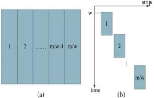
architecture based on this design concept is illustrated in Section IV.For images of large size, we could not
access a whole row simultaneously as the output data width of memory that stores image pixels is limited. To
solve this problem, we divide the image into several “strips.” As shown in Fig. 5(a), we first compute the
integral image of strip 1 and store the rightmost integral value of each row of strip 1. Then, we use the property
mentioned in Section II to compute the integral image values in strip 2. Similarly, we store the rightmost
integral value of each row of strip 2 and compute the integral image values in strip 3. We repeat the same
operations for the rest strips. These strips are computed in a pipeline way, as shown in Fig. 5(b). For an m × n
image, if the width of each strip is w (Usually m could be exactly divided by w), it will take n steps to compute
each strip, and there would be m/w strips. In addition, each strip is computed using a pipelined structure with
cascaded row
Fig. 5. ‘Strips’ mechanism for large image. (a) Image is divided in to strips. (b) Strips are processes in
1675 | P a g e
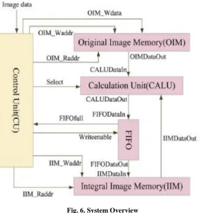
Fig. 6. System Overview
and column operations, which causes a delay of w steps in the cascaded structure to fill the pipeline. Thus, in
total, it will take
Snum steps to compute the integral image. Snum is defined as
By selecting an appropriate value of w, we can achieve the highest efficiency by trading off between speed, area,
and power dissipation.
IV. VERIFICATION
In this section, the proposed architecture is implemented on a field-programmable gate array (FPGA), and the
functionality and system performance are evaluated. Details of our experiment are shown in the following.
A. Experiments Set Up
We adopt 3000 sample images to evaluate the average performance of this brief. These images are in multiple
sizes (640 × 480, 1280 × 720, 1920 × 1080, and 4096 × 2160) used in our experiment. According to review, we
1676 | P a g e
TABLE I
FUNCTIONALITY VERIFICATION
TABLE II
COMPUTATION SPEED
TABLE III
HARDWARE RESOURCES
When testing on the same set of images, the average detection rate (DR) and false positive rate (FPR) are the
same, which means that the integral images computed by different schemes are the same. These results prove
that our architecture achieves the correct integral image data. For different sets of images, DR and FPR are
different due to the different image contents in different image sets.
C. System Performance
The comparison results of processing speed on different sizes of images are listed in Table II. The area (number
of LEs)of integral computing unit and CU are shown in Table III. In experiments, the memory including the
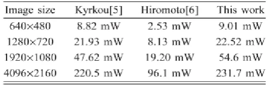
input memory for original images and output memory for integral images are the same for Kyrkou’s method [5], Hiromoto’s method [6], and this brief. In addition, we present the synthesis power results of different sizes of
images in Table IV. In this brief, for an m × n image, the time complexity is O(n), whereas it is O(2m + n) in
Kyrkou’s method and O(mn) in Hiromoto’s method.
Meanwhile, the pipeline manner of cascade accumulation by row greatly improves the processing efficient. As
shown in Table II, this brief achieves the highest speed for images with different sizes. Since we design the
1677 | P a g e
power and hardware cost per operation in integral image computing are largely reduced, although the totalpower and area cost are slightly higher than Kyrkou’s method and Hiromoto’s method as shown in Tables III
and IV. The power efficiency (i.e., computation speed per unit power) and area efficiency (i.e., computation
speed per unit area) is related to processing speed, power, and hardware resource. By choosing w = 32 in the
CALU design, the power efficiency and area efficiency are also improved. This is because that our
TABLE IV
POWER CONSUMPTION
TABLE V
SPEED PER UNIT AREA
TABLE VI
SPEED PER UNIT POWER
parallel architecture improves the data reuse and reduces the memory access cost per operation, resulting in high
power and area efficiency. As shown in Tables V and VI, our speed per unit area is 3.61 ∼3.66 times higher
1678 | P a g e
V. CONCLUSION
In this brief, According to Peng Ouyang, Shouyi Yin, Yuchi Zhang, Leibo Liu, and Shaojun Wei proposed a fast
integral image computing method and construct the parallel and pipelined architecture.Compared with
state-of-the-art methods, the proposed architecture achieves fast computation speed with higher power and area
efficiency. According to review we can improve a fast integral image computing method and construct the
parallel and pipelined architecture with high area and power efficiency. This architecture can be used in
embedded systems for many vision based applications that depends on integral image computing.
REFERENCES
[1] R. Lienhart and J. Maydt, “An extended set of haar-like features for rapid object detection,” in Proc. Int.
Conf. Image Process., 2002, vol. 1, pp. I-900–I-903.
[2] R. Miyamoto et al., “Pedestrian recognition in far-infrared images by combining boosting-based detection
and skeleton-based stochastic tracking,” in Advances in Image and Video Technology. New York, NY,
USA: Springer-Verlag, 2006, pp. 483–494.
[3] Y. Hanai, Y. Hori, J. Nishimura, and T. Kuroda, “A versatile recognition processor employing haar-like feature and cascaded classifier,” in Proc.IEEE ISSCC, 2009, pp. 148–149.
[4] H. Bay, T. Tuytelaars, and L. Van Gool, “Surf: Speeded up robust features,” in Computer Vision-ECCV
2006. New York, NY, USA: Springer-Verlag, 2006, pp. 404–417.
[5] C. Kyrkou and T. Theocharides, “A flexible parallel hardware architecture for adaboost-based real-time
object detection,” IEEE Trans. VLSI Syst., vol. 19, no. 6, pp. 1034–1047, May 2010.
[6] M. Hiromoto, H. Sugano, and R. Miyamoto, “Partially parallel architecture for adaboost-based detection
with haar-like features,” IEEE Trans. CircuitsSyst. Video Technol., vol. 19, no. 1, pp. 41–52, Dec. 2009.
[7] F. C. Crow, “Summed-area tables for texture mapping,” ACM SIGGRAPH Comput. Graph., vol. 18, no. 3,