Scholarship@Western
Scholarship@Western
Electronic Thesis and Dissertation Repository
1-16-2014 12:00 AM
Numerical Simulation of Liquid-Solid Circulating Fluidized Beds
Numerical Simulation of Liquid-Solid Circulating Fluidized Beds
Abbas Dadashi
The University of Western Ontario
Supervisor Dr. Chao Zhang
The University of Western Ontario Joint Supervisor Dr. Jesse Zhu
The University of Western Ontario
Graduate Program in Mechanical and Materials Engineering
A thesis submitted in partial fulfillment of the requirements for the degree in Master of Science © Abbas Dadashi 2014
Follow this and additional works at: https://ir.lib.uwo.ca/etd
Part of the Computational Engineering Commons
Recommended Citation Recommended Citation
Dadashi, Abbas, "Numerical Simulation of Liquid-Solid Circulating Fluidized Beds" (2014). Electronic Thesis and Dissertation Repository. 1874.
https://ir.lib.uwo.ca/etd/1874
This Dissertation/Thesis is brought to you for free and open access by Scholarship@Western. It has been accepted for inclusion in Electronic Thesis and Dissertation Repository by an authorized administrator of
Numerical Simulation of Liquid-Solid
Circulating Fluidized Beds
(Thesis format: Integrated-Article)
By
Abbas Dadashi
Graduate Program
In
Engineering Science
Department of Mechanical & Materials Engineering
A thesis submitted in partial fulfilment
of the requirements for the degree of
Master of Science
The School of Graduate and Postdoctoral Studies
The University of Western Ontario
London, Ontario
ii
Abstract
Liquid-solid circulating fluidized bed (LSCFB) reactors are obtaining extensive attraction in the extraction process of functional proteins from industrial broth. A typical LSCFB is comprised of a riser, a downcomer, a liquid-solid separator, a top solids-return pipe and a bottom solids-return pipe. In light of the literature review conducted in this research, a detailed modeling of the protein extraction using an LSCFB ion-exchange system requires a microscopic study including hydrodynamic field, mass transfer and kinetics reactions.
A computational fluid dynamics (CFD) model was developed to simulate the hydrodynamics of the two phase flow in an LSCFB riser. The model is based on Eulerian–Eulerian (E-E) approach incorporating the kinetic theory of granular flow. The predicted flow characteristics agree well with our earlier experimental data. Furthermore, the model can predict the residence time of both liquid and solid phases in the riser using a pulse technique.
A numerical model was developed to predict the protein extraction process using an LSCFB ion exchange system. The model for the riser is an extension of the previous CFD hydrodynamic model for the riser incorporating the kinetics reaction. The model for the downcomer includes a one-dimensional mathematical model using the adsorption kinetics correlations. The numerical predictions were compared favorably with the experimental data from a lab-scale system. The model was used to investigate the effects of operating condition on the protein production rate and the system efficiency.
For further study on the hydrodynamics in the downcomer of an LSCFB, the CFD technique was used to simulate the counter-current two phase flow in the downcomer. The model is based on E-E approach incorporating the kinetic theory of granular flow. The predicted results agree well with our earlier experimental data. Furthermore, it is shown that the bed expansion of the particles in the downcomer is directly affected by the superficial liquid
velocity in downcomer and solids circulation rate.
As results, it is demonstrated that the developed CFD model can be adapted to simulate and
iii
Keywords
iv
Co-Authorship Statement
Chapters 2, 3 and 4 of this thesis have been submitted for publishing in journals.
v
Acknowledgments
I would like to express my sincere gratitude to Professors Chao Zhang and Jesse Zhu for their guidance throughout this research. As my supervisors, their advice, encouragement, patience, and financial support were the driving force for me to conduct and complete the work.
I would also like to thank the Natural Sciences and Engineering Research Council of Canada (NSERC) for their financial support through the NSERC Discovery Grants to Profs. Zhu and Zhang and the NSERC Engage Grant sponsored by Renix Inc.
I would also like to thank all the members from Prof. Zhang and Prof. Zhu’s research groups, especially Mehran Andalib, Rajeev Kumar, Lei Kong, Amin Jaberi and Rajib Saha for their help and friendship through these years.
vi
Table of Contents
Abstract……… ii
Co-Authorship Statement……….iv
Acknowledgments………..v
Table of Contents………..vi
List of Tables……….x
List of Figures………...xi
Nomenclature………..xiv
Chapter 1………1
1 General introduction………..1
1.1 Background……….1
1.2 Literature review……….5
1.2.1 Hydrodynamic characterization of LSCFB……….5
1.2.2 CFD models……….9
1.2.3 Protein extraction from biological broth using an LSCFB ion exchange system………...13
1.3 Objectives and thesis structure ……….17
References……….19
vii
2 A Computational Fluid Dynamics Study on the Flow Field
in a Liquid-Solid Circulating Fluidized Bed Riser ………..22
2.1 Introduction………...22
2.2 Experimental setup of the LSCFB system ………...24
2.3 Mathematical modeling ………25
2.3.1 Governing equations ……….26
2.3.2 Boundary conditions ……….28
2.4 Numerical methodology ………...32
2.5 Results and Discussion ……….32
2.5.1 The effect of turbulence models………33
2.5.2 Effect of liquid superficial velocity………...35
2.5.3 Effect of solids circulation rate………..36
2.5.4 Residence time distribution………...37
2.6 Conclusions………...40
References……….42
Chapter 3………..44
3 CFD modeling of continuous protein extraction process using liquid-solid circulating fluidized beds……….………..44
3.1 Introduction ………..44
3.2 Experimental setup of the LSCFB system………46
viii
3.2.2 Materials………49
3.2.3 Kinetics of Ion Exchange mechanism in the LSCFB System…………...49
3.3 Mathematical modeling……….50
3.3.1 CFD modeling of flow field and mass transfer in the Riser………..50
3.3.2 Hydrodynamics and mass transfer simulation in downcomer…………...51
3.3.3 Parameters of modeling……….55
3.3.4 Numerical methodology………56
3.4 Results and Discussion………..58
3.4.1 Validation of the numerical model………59
3.4.2 Effect of the liquid velocity in the downcomer……….63
3.4.3 Effect of the liquid velocity in the riser……….64
3.4.4 Effect of the feed concentration……….64
3.4.5 Evaluation of the system efficiency and protein production rate………..66
3.5 Conclusions………...67
References……….68
Chapter 4………..72
4 Numerical Simulation of Counter-Current Flow Field in the Downcomer of a Liquid-Solid Circulating Fluidized Bed………...72
4.1 Introduction………...72
4.2 Configuration of the LSCFB ion-exchange system………..72
ix
4.3.1 Governing equations………..75
4.3.2 Boundary conditions………..75
4.4 Numerical methodology………78
4.5 Results and Discussion………..78
4.5.1 Validations of the numerical model………...80
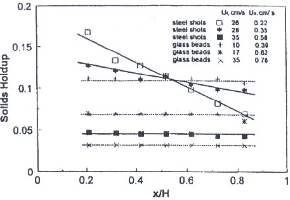
4.5.2 Effect of superficial liquid velocity on solids holdup………81
4.5.3 Effect of solids circulation rate on solids holdup………..82
4.5.4 Radial distribution of the solids holdup……….83
4.5.5 Effect of superficial liquid velocity on the dispersion of the solid particles……….84
4.6 Conclusions………...85
Reference….………..87
Chapter 5………..89
5 Conclusions………..89
x
List of Tables
Table 2.1: The constitutive correlations for closure of the transport equations 30
Table 3.1: Properties of Diaion HPA25 ion-exchange particles (Lan et al. 2002) 49
Table 3.2: Governing equations for liquid-solid flows in the riser 52
Table 3.3: Model parameters (Lan et al., 2000) 56
Table 3.4: Protein production rate and system efficiency under different operating conditions
66
xi
List of Figures
Figure 1.1: Schematic diagram of the liquid–solid circulating fluidized bed
(LSCFB) reactor 2
Figure 1.2: The axial solid holdup distribution along the upper dilute zone of LSCFB riser for glass beads and steel shots, under different liquid velocity (Zheng et al., 1999)
7
Figure 1.3: Radial profiles of solids holdup at the level H = 0.8m (a) for different solids flow rates (b) for different superficial liquid velocities. (Zheng et al. 2001)
8
Figure 1.4: The radial distribution of the liquid velocity under Gs = 5 kg/m2s and different liquid velocities for glass beads (Zheng et al. 2002)
9
Figure 2.1: Schematic diagram of the liquid-solid circulating fluidized bed
(Zheng et al., 2003)
25
Figure 2.2: The computational domain in the LSCFB riser 31
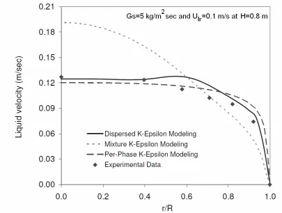
Figure 2.3: Comparison of the liquid velocity profile using three types of the k-ε
multi-phase turbulence models (Experimental data by Zheng et al. (2003))
33
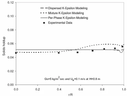
Figure 2.4: Comparison of the solids holdup profile using three types of k-ε
multiphase turbulence models (Experimental data by Zheng et al. (2002))
34
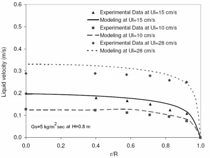
Figure 2.5: Comparison of the radial distributions of the liquid velocity under
different liquid superficial velocities (Experimental data by Zheng et
al. (2003))
35
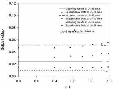
Figure 2.6: Comparison of the radial distributions of the solid holdup under
different liquid superficial velocities (Experimental data by Zheng et
al. (2002))
36
Figure 2.7: The radial distributions of the solid holdup under different solids
circulation rates (Experimental data by Zheng et al. (2002))
xii
Figure 2.8: The residence time distributions of (a) the liquid phase and (b) the
solids phase at Gs=5 kg/m2sec and Ul =10 cm/s
39
Figure 2.9: The residence time distributions of (a) the liquid phase and (b) the
solid phase at Gs=5 kg/m2sec and Ul =15 cm/s
40
Figure 3.1: Schematic diagram of the LSCFB ion-exchange system Lan et al. (2000)
48
Figure 3.2: Computational domain of in the downcomer and riser of the LSCFB. (a) Downcomer and (b) Riser
58
Figure 3.3: Comparison of the liquid protein concentration along the downcomer
at different superficial liquid velocities (Uld) in the downcomer at
Cod=2 kg/m3, Gs=1.24 kg/m2/s, Ulr=0.0113 m/s (Experimental data by
Lan et al. (2000, 2002a))
60
Figure 3.4: Comparison of the liquid protein concentration along the riser at
different superficial liquid velocities (Ulr) in the riser at Cod=2 kg/m3,
Gs=1.24 kg/m2/s, Uld=0.006 m/s (Experimental data by Lan et al.
(2000, 2002a))
61
Figure 3.5: Contour of the protein concentration of the liquid n the riser, Cr
(kg/m3)
62
Figure 3.6: Variation of the liquid protein concentration along the riser at
different superficial liquid velocity in downcomer, Uld(Cod=2 kg/m3, Gs=1.24 kg/m2/s, Ulr=0.0113 m/s)
63
Figure 3.7: Influence of the feed protein concentration (Cod) on the protein
concentration of the liquid phase at Gs=1.24 kg/m2/s, Uld=0.0006
m/s, and Ulr=0.0113 m/s. (a) downcomer, (b) riser
65
Figure 4.1: Schematic diagram of the LSCFB ion-exchange system Lan et al. (2000)
73
Figure 4.2: Schematic diagram of the computational domain to simulate the liquid-solid flow in the downcomer of the LSCFB
xiii
Figure 4.3: Predicted solids holdup distribution in the downcomer at Uld = 0.55
mm/sec and Gs=0.05 kg/m2sec
79
Figure 4.4: Comparison of numerical and experimental results for the average
solids holdup in the dense zone of the downcomer (Experimental data by Lan et al. (2000))
81
Figure 4.5: Variation of the solids holdup in the dense zone of the downcomer
(αsd) at different superficial liquid velocity
82
Figure 4.6: Variation of the solids holdup in the dense zone of the downcomer
(αsd) at different solids circulation rates
83
Figure 4.7: Radial distribution of the solids holdup in the dense zone of the
downcomer at Gs=0.05 kg/m2sec and x=1.5 m
84
Figure 4.8: The residence time distributions of the solid phase at Gs=0.05
kg/m2sec and (a) Uld =0.55 mm/sec, (b) Uld =0.65 mm/sec
xiv
Nomenclature
Notation Greek letters
a Specific surface area of the
ion-exchange resin (Ap/Vp) (m2/m3)
s
α Local solids volume fraction,
dimensionless
C Protein concentration in liquid
phase (kg/m3)
s
α Mean solids volume fraction at certain cross-section, dimensionless
C1ε Constants αsd solids volume fraction in the dense
zone of the downcomer
C2ε Constants
ε
Turbulent energy dissipation rate,m2 /s3
CD Drag coefficient, dimensionless kΘs Granular conductivity, kg/m 3 s dp Mean particle diameter, m
γ
Θ Collisional energy dissipation rate,kg/(m s3)
D Riser diameter, m Φls Interphase Energy exchange, kg/(m s3)
e Restitution coefficient for interparticle collisions, dimensionless
s
α Local solids fraction, dimensionless
ew Restitution coefficient for
particle-wall collisions, dimensionless
ε
sSolid holdup
g Acceleration due to gravity, m/s2
ε
l Bed voidage g0 Radial distribution function,dimensionless Θ Granular temperature, m
2/s2
Gs Solids circulation rate, kg/(m2 s) λ Solids bulk viscosity, kg m/s
k Turbulent kinetic energy, m2 /s2 µ Viscosity, kg m/s
kf Film mass transfer coefficient (m/s)
υ
Kinematic viscosity, m2/sKd Dissociation constant (kg/m3) ρ Density, kg/m3
KL Lumped mass transfer rate
coefficient (m/s) σk
Constants
sl
K Interphase Momentum exchange
coefficient, kg/(m3 s) σε
Constants
kr Desorption rate constant (s-1)
τ
Shear stress, kg m/s2n Bed expansion index kΘs Granular conductivity, kg/(m
3 s) ps Solids pressure, Pa ψ Constant factor which indicates the
xv
P Fluid pressure, Pa Subscripts
Re Reynolds number, dimensionless l liquid phase
t Time (s) s solid phase
Ut Particle terminal velocity, m/s f fluid
U Superficial liquid velocity, m/s a auxiliary
v Velocity, m/s eq Equilibrium
z Distance from bottom of downcomer, m
d Downcomer
Chapter 1
1
General introduction
1.1 Background
Fluidization is characterized as a phenomenon which a bed of particles gains properties of fluid and is converted from solid state to fluid state. Fluidization occurs when fluid flow is introduced in the bottom of a bed of solids particles at such a velocity that the buoyed weight of the particles is completely supported by the drag force imposed by the fluid. As a result, the particles are able to move in the bed. The term “fluidization” reflects this state of fluid-like properties onto the solid particles, as the term liquefaction is used to denote the act of making liquid properties.
Fluidized-bed includes gas–solid, liquid–solid and gas–liquid–solid fluidized-beds in terms of the fluid–particulate systems. With respect to bed scheme and operation, there are the stationary fluidized beds (SFB) or fixed fluidized beds (FFB), where the particles essentially stay in the fluidized bed and the circulating fluidized beds (CFB), where particles are mostly entrained out of the fluidized beds but at the same time recirculated back to or fresh particles added to the same fluidized beds. SFB are often called conventional fluidized beds since they were the first to be used in various industrial applications. In liquid–solid systems, the SFB basically has only one operating regime, the particulate fluidization regime, where the particles are uniformly distributed in the upflowing liquid.
Figure 1.1. The major components of an LSCFB include a riser, a down-comer, a liquid-solid separator, a top liquid-solids-return pipe and a bottom liquid-solids-return pipe.
Figure 1.1: Schematic diagram of the liquid–solid
The first modern application of a fluidized-bed reactor was a stationary, dense-phase gas– solid fluidized-bed reactor (Winkler, 1922) operated for coal gasification in Germany to produce synthesis fuel from coal. It started with gas-solid fluidization and then extended to liquid-solid and gas-liquid-three-phase fluidization. The first type of CFB reactor was gas-solid CFB reactor which was proposed in the late 1960’s. They have been used in many different kinds of industries during last 30 years.
In comparison to gas-solid system, the LSCFB and the gas-liquid-solid circulating fluidized bed (GLSCFB) have received too many attentions until recent years. The CFB has some advantages over conventional fluidized bed such as high gas/liquid velocity, low backmixing, larger processing capability, better interphase contact and good heat and mass transfer capabilities (Yang et al., 1993). On the other hand, solid particles or catalysts are very expensive and need to be continuously regenerated and also, most of the bio-processes and gasifiers prefer continuous mode of operation. In those cases, the deactivated catalysts, bio-media, ion exchange resins, or adsorbents can be regenerated continuously by CFB reactors (Zhu, 2000). Because of these advantages, LSCFBs have applied in a wide range of chemical processes including wastewater treatment, continuous protein recovery from cheese whey and so on.
A number of models have been developed to describe the protein adsorption and desorption behavior in different kinds of fluidized beds considering various types of approximation to physical reality (Wright and Galsser, 2001; Ping et al., 2005 and
Gaikwad et al. 2008). However, detailed hydrodynamics of the LSCFB was not included
in their models and they assumed that the distribution of solid holdup (εs), solid velocity
(us) and liquid velocity (ul) are uniform along the riser and downer.
On the other hand, some comprehensive experimental studies on the hydrodynamics of LSCFBs have been reported (Liang and Zhu, 1997; Liang et al., 1996 and 1997; Zheng et al., 1999 and 2002 and Zheng and Zhu, 2003). In particular, the radial flow structure in the riser of an LSCFB was investigated by Liang et al. (1996) and Zheng et al (2001). They pointed out that unlike the conventional liquid–solids fluidized bed, the radial distribution of bed voidage (εl) is not uniform for glass beads in the liquid–solids
circulating fluidization regime. In fact, the core-annulus structure mechanisms were observed, so solid holdup was high near the wall and low at the central part of riser. Zheng et al. (1999) have studied the axial hydrodynamic behavior of an LSCFB using three different particles of nearly same size. They have observed that because of the arrangement of the riser distributor, two distinct zones (based on their solid holdup) were established along the riser named as a dense zone at the bottom of riser and as a dilute zone at the upper part of riser.
Experimental data demonstrate that axial and radial hydrodynamic properties are not uniform along the riser of an LSCFB and a complete modeling of the protein extraction using an LSCFB ion-exchange system requires a microscopic study on the nature of this system including hydrodynamic field, mass transfer and kinetics reactions. It is of fundamental importance for designing and scaling up LSCFB ion-exchange systems and optimizing operating parameters.
1.2
Literature review
The literature review is conducted in three areas, (1) experimental studies on hydrodynamic characteristics of LSCFB, (2) the review of relevant computational fluid dynamics (CFD) models on two-phase flow and (3) investigation of protein extraction process based on ion exchange system.
1.2.1
Hydrodynamic characterization of LSCFB
Many Experimental studies have been carried out about conventional liquid-solid fluidization in the 1950s. Their results confirm that almost all liquid-solid systems fluidized at liquid velocities below the particle terminal velocity are indeed homogenous and axial and radial distributions of particles are uniform (Richardson and Zaki, (1954)). In 1954, Richardson and Zaki made a significant contribution to this field by proposing a simple relationship between the operating liquid velocity and the bed voidage. Later, Kwauk (1963) suggested that the concept developed by Richardson and Zaki (1954) could also be used to identify co-current and countercurrent liquid-solid flow.
When the liquid velocity of riser is higher than the critical transition velocity, particles start circulating between two columns (riser and down-comer). Zheng et al. (1999) illustrated the variation of the solid circulation rate, Gs, with respect to superficial liquid velocity in riser. They observed two different types of the circulating fluidization regime for a given auxiliary liquid flow: (1) above particle terminal velocity, the initial circulating fluidization regime in which solid circulation rate increases quickly with increase in liquid flow rate and (2) with further increase in the liquid velocity, the developed circulating fluidization regime where solid circulation rate increases insignificantly with increase in liquid flow rate.
Figure 1.2: The axial solid holdup distribution along the
upper dilute zone of LSCFB riser for glass beads and steel
shots, under different liquid velocity (Zheng et al., 1999)
The radial flow structure in the liquid–solids circulating fluidization regime has been examined by Liang et al. (1996). They pointed out that unlike the conventional liquid– solids fluidized bed, the radial distribution of bed voidage is not uniform for glass beads, in the liquid–solids circulating fluidization regime. However, this work was carried out with only one type of particles under limited operating conditions.
(b)
Figure 1.3: Radial profiles of solids holdup at the level H = 0.8m (a) for different solids flow rates (b) for different superficial liquid velocities. (Zheng et al. 2001)
Liang et al. (1996) and Zheng et al. (2002) have conducted a study on the local liquid velocity distributions and reported that a non-uniform distribution of liquid velocity also exists in the LSCFB. It is seen that liquid velocity are higher at the axis of the riser and lower near the wall. In Figure 1.4, the radial non-uniformity is seen to increase with increasing superficial liquid velocity. On further increasing the liquid velocity, the radial non-uniformity of local liquid velocity distribution decreases due to the transition from the circulating fluidization regime to the dilute liquid transport regime (Liang et al., 1996).
demonstrate that the increase in theliquid superficial velocity steepens the radial profiles of particle velocity in the operating range of their study. They also found that the radial profiles of particle velocity do not change significantly with the axial position.
Figure 1.4: The radial distribution of the liquid velocity under Gs = 5 kg/m2s and different liquid velocities for glass beads (Zheng et al. 2002).
1.2.2 CFD models
In recent decades, CFD techniques have received a lot of attentions in simulating the transport phenomena in two-phase fluidized beds. CFD simulations are able to give very
detailed information about the local values of solid hold-up (εs), liquid phase flow
patterns and the intermixing levels of the individual phases especially in the regions where measurements are either difficult or impossible to obtain. Such information can be useful in the understanding of the transport phenomena in fluidized beds.
to solve dense two-phase flow which has a large number of particles. Therefore, at present, this method can only be applied to some engineering cases which two-phase flow is dilute enough.
In the Eulerian-Eulerian approach, also well known as two fluid model, each phase is treated as an interpenetrating continuum and the concept of phasic volume fraction is introduced. The conservation equations of mass, momentum, and energy for both the particulate and the fluid phases are derived which have similar structure for all phases. In order to close pseudo N-S equation for solids phase, some constitutive correlations are required for solid-phase viscosity, pressure and stresses. So far, some researches have developed various assumptions to derive these correlations.
In the case of two-phase flow in the fluidized beds where the number of solids particles is huge, The E-E approach is the more attractive and practical method. That’s why it has been widely used for simulations of two-phase flows in fluidized beds. Two fluid model was originally developed by Jackson (1963), Soo (1967), Garg and Pritchett (1979) to simulate the flow structure of bubbling fluidized beds. Their models were based on the assumptions of zero gas and solids viscosities. They were able mainly to predict the behavior of bubbling beds. Another heavily simplified model was constant-viscosity model introduced by Tsuo and Gidaspow (1990) to the simulation of riser column. They assumed that the particle viscosity is 200 times of the gas viscosity. Although this treatment was greatly approximated and highly empirical, their model was claimed to predict some flow patterns in the riser of circulating fluidized bed. However, these models are not quantitative enough to give accurate results close to experimental data.
random particle velocity is then defined. In this Theory, the usual thermal temperature is replaced by a granular temperature for which a differential equation is derived using the methods of kinetic theory. Thus the solid viscosity and the solid stress are a function of this granular temperature, which varies with time and position in a fluidized bed.
Though the published works on CFD modeling of fluidized beds are mostly on the gas-solid fluidized beds, a few CFD studies are available on the liquid-gas-solid fluidized beds. Liquid-fluidized beds should, at least in principle, be simpler to model than gas-fluidized beds, since the hydrodynamics are more homogeneous, turbulence is much less of a factor, and the density difference between the two phases is reduced. Inter-particle collisions are also greatly attenuated, or even absent (Gidaspow and Lu, 1998) due to the liquid film separating particles as they approach each other.
Roy et al (2001) presented a two-fluid model based on the KTGP to simulate the LSCFB riser for alkylation process. The drag force correlation of Wen and Yu was applied to model momentum exchange between two phases. The liquid-phase turbulence was modeled using the standard k-
ε
model. No-slip condition was used at the wall for the liquid (continuous) phase. Johnson and Jackson boundary conditions were applied for velocity and granular temperature of solid phase on the wall. At the inlet, the boundary conditions were set to impose a uniform solids-liquid distribution. The purely convective flow was assumed as the outlet boundary conditions and also the symmetry conditions were imposed at the central axis of the column. Sensitivity to restitution coefficients (e) was examined and the predicted profiles were found not very sensitive to the restitution coefficient in the vicinity of e=1.0. The computed solid velocity vectors indicated solids rising in the middle and flowing down near the walls; moreover, they were in a qualitative agreement with experimentally observed flow patterns. They achieved a typical set of residence time distribution (RTD) curves for the solids and liquid evaluated from solving the scalar transport equations for each phase which were in agreement with experimental data.based on Eulerian–Eulerian approach to simulate the laminar regime in the mono-dispersed and binary-mono-dispersed suspensions. For the solid phase, the viscous stress term was neglected. The Richardson and Zaki correlation was used for the drag coefficient. The no-slip condition was imposed on the fluid velocity at the wall while particles were allowed to slip freely at all walls. A maximum possible particle volume fraction of 0.58 was enforced. The numerical results illustrated the effect of the fluidization superficial velocity on the average volume fraction. The CFD models successfully predicted the general trends in the experimental data. They indicated that some CFD model limitations have contributed to the observed deviations between the experimental results and CFD predictions. First, the modified fluidized bed was simulated with a two-dimensional model to reduce computational time, although the suspension is three- dimensional phenomenon. Second, the particle size distribution and the interaction between the solid phases for the binary system of particles were ignored and a laminar flow regime was assumed throughout the vessel.
Lettieri et al. (2006) used the CFD modelling based on Eulerian–Eulerian approach to simulate a liquid fluidized bed of lead shot in slugging mode. The granular kinetic theory was applied to describe the solids pressure and the solid phase stress tensor. The radial distribution function (go) given by Ding and Gidaspow (1990) was used in their work.
The inter-phase momentum exchange was modeled by an equation presented by Gidaspow and Ihme (1994). No-slip boundary conditions were applied for both phases on the wall. The uniform gas inlet velocity was employed as a boundary condition at the bottom of the riser. Pressure boundary conditions were employed at the top of the riser. This implies Dirichlet boundary conditions on pressure and all flow quantities were of zero normal gradient. Results from simulations were analyzed in terms of voidage profiles, bed expansion, pressure drop and pressure fluctuations. The CFD results showed an agreement with the experimental data at low liquid velocities. However, modeling was not able to predict flow structure at high liquid velocity, reasonably.
demonstrated that the mesh size, time step and convergence criteria are three inter-related parameters. They’ve shown that the Courant number (u∆t/∆x) in the range 0.03< Courant No.<0.3 gives the best results which are independent of mesh, time step, and convergence criterion. Also, they have applied both uniform and non-uniform (discrete-hole) distributor at the inlet and flow characteristics was compared between the two distributors. The non-uniform distributor caused a slight decrease in overall bed voidage compared to a perfectly uniform distributor. Also, the perfectly uniform distributor resulted in fewer swirls than the non-uniform distributor. It was also shown that particles near the distributor ascend near the wall and descend in the core, while this pattern reverses in the upper part of the column which is in agreement with the experimental data. The difference between the upward and downward velocities may be caused by a non-uniform radial distribution of voidage, with lower voidage in the downflow region than in the upflow region. The CFD and experimental results were also compared with the predictions from the well-known Richardson and Zaki (1954) equation. The CFD model consistently underpredicts the voidage, but, except at the highest superficial liquid velocities, the predictions are better than those from the Richardson and Zaki equation and within 5% of the experimental data.
1.2.3 Protein extraction from biological broth using an
LSCFB ion exchange system
One of the common separation methods which are used to extract the protein from biological broth is the ion exchange mechanism. In this section, the principles of ion exchange particle are discussed first and then it’s followed by an emphasis on its application in protein recovery.
An anion exchanger can be represented as Resin-F+ E- which Resin-F+ denotes the inert matrix containing the positive fixed ion (functional group) and E-indicates the counter-ion. When an anion exchange particle is submerged in a solution containing a different anion, A-, the ion exchange will process as following:
When an ion exchanger particle is placed in an aqueous solution, the pores will fill with solution and a sufficient concentration of counter-ions to maintain the overall electric balance in the particle. The counter-ion can move through the matrix by diffusion or under the influence of an electric field. These counter-ions are thus exchanged with ions of the same charge from the bulk solution and this step is the base of the ion exchange process.
The continuous ion exchange processes using different types of fluidized beds were extensively investigated (Byers et al., 1997; Gordon et al., 1990; Higgins, 1969; and Himsley, 1981). The application of conventional fluidized beds for ion exchange process has some benefits such as the low and stable bed pressure drop and the direct application of unclarified whole broth feed. As reviewed by Zhu et al. (2000), compared with conventional fluidized beds, circulating fluidized beds have many advantages including continuous operation with adsorption and desorption carried out simultaneously, high throughout due to high liquid velocity in the riser, highly efficient liquid-solid contact, favorable mass and heat transfer, maintaining the nearly plug flow condition in the riser which reduced back-mixing of phases and integrated reactor and smaller processing volumes. (Felice, 1995; Fan, 1989; and Lan et al., 2000).
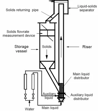
The schematic of the LSCFB ion exchange system used by Lan et al. (2000) for continuous protein extraction is shown in Figure 1.1. The major components of the LSCFB extractor include a riser, a downcomer, a liquid-solid separator, a top solids-return pipe, a bottom solids-solids-return pipe, a top washing section, a bottom washing section, a riser distributor and a downcomer distributor. The riser is 3.0 m in height and 0.038 m in diameter, and the downcomer is 2.5 m in height and 0.120 m in diameter.
can flow down from the top of downcomer. As a result, the particles are able to circulate between the two columns.
The distributor for the downcomer is a tubular ring that is carefully designed in order to have a uniform liquid distribution while allowing the solids to flow down. The riser distributor divides the incoming stream into two streams: the primary and auxiliary streams. The primary stream enters through a tubing of 1.1 cm in ID extending 5.1 cm into the riser. The outlet of the primary stream was located above the solids entrance at the bottom of the riser. Also, the auxiliary stream is introduced through a perforated plate at the bottom of the riser. The particles at the bottom are mobilized by the auxiliary stream, and then the particles are entrained up along the riser by the combination of the primary and auxiliary streams.
The dynamic seals between the riser and downcomer are achieved by maintaining the two solids return pipes in the moving packed-bed regime. The top wash section and the bottom wash section clean the particles before they entering the solids return pipes to avoid penetrating liquid solution from one column to another. The solids circulation rate is controlled by a butterfly valve installed on the bottom solids return pipe. The solids circulation rate was measured by a device which is installed at the top of the downcomer and made of a central vertical plate and two half butterfly valves.
Bovine serum albumin (BSA) was used as model protein and continuous recovery of BSA solution in the LSCFB ion exchange system was conducted with the BSA solution as feed in the downcomer and 0.4 M NaCl solution as the extracting buffer in the riser. Diaion HPA25 particles were used as ion-exchange particles for all BSA adsorption-desorption studies.
be kept up large enough to allow the passage of the colloids in the feed without clogging the bed. In other words, an unclarified broth containing colloids can be treated directly by an LSCFB extractor without preclarification. This will significantly simplify the overall purification scheme.
1.3
Objectives and thesis structure
In light of the literature review presented in the previous sections, it is seen that a number of CFD modeling has been done on the hydrodynamics of LSCFBs. Some kinetic models have also been developed to describe the protein adsorption and desorption behaviors in different kinds of fluidized beds considering various types of simplifications to physical reality (Wright and Galsser, 2001; Ping et al., 2005; and Gaikwad et al., 2008). However,
detailed hydrodynamics of the LSCFB was not included in their kinetic models and they
assumed that the distribution of solid holdup (εs), solid velocity (Us) and liquid velocity
(Ul) are uniform throughout the riser and downcomer. In contrast, experimental data
have demonstrated that both axial and radial distributions of hydrodynamics properties are not uniform along the riser of an LSCFB.
As a result, a complete modeling of the protein extraction using an LSCFB ion-exchange system requires a microscopic study on the nature of this system including hydrodynamics field, mass transfer and kinetics reactions. It is of fundamental importance for designing and scaling up LSCFB ion-exchange systems and optimizing operating conditions.
At this research work, first, the hydrodynamics field of an LSCFB riser will be simulated by Eulerian-Eulerian model based on the kinetics theory of granular flow. Then, the influence of operating conditions such as liquid superficial velocity and solids holdup on the flow structure will be investigated. And next, in order to simulate the protein extraction process using the LSCFB ion-exchange system, the mass transfer model of the protein species will be coupled to the initial CFD model for the hydrodynamics. Finally, a CFD model is developed to capture the hydrodynamic characteristics of the counter-current flow in the downcomer of the LSCFB. Therefore, the thesis structure is as follows:
Chapter 2 reports a numerical investigation on the hydrodynamics of the LSCFB riser using a CFD model based on Eulerian-Eulerian approach and incorporating the granular kinetics theory.
Chapter 3 presents a sophisticated numerical model to simulate the protein extraction process using the LSCFB ion-exchange system. This model will take into account a more accurate study on the nature of this system including hydrodynamics, mass transfer and kinetics. A axisymmetric CFD model is developed to capture the detailed information about the local values of volume fraction, velocity and protein concentration of both the liquid stream and the solid particles in the riser. In addition, the adsorption process in the LSCFB downcomer is simulated by a one-dimensional mathematical model using the adsorption kinetics correlations.
Chapter 4 reports a CFD model to simulate the hydrodynamics of the counter-current two phase flow in the downcomer of the LSCFB. The model is based on Eulerian-Eulerian (E-E) approach incorporating the kinetic theory of granular flow. Furthermore, the effect of operating condition on hydrodynamic characteristic is examined.
Chapter 5 summarizes the key results from all above studies and recommends the future work.
Therefore, the results of this research would expand our knowledge on:
(1) Nature of hydrodynamics of the two phase flow in an LSCFB riser.
(2) Detailed simulation of the protein extraction process from industrial broth using an LSCFB ion-exchange system
(3) Optimization of the protein extraction process from industrial broth using an LSCFB ion-exchange system.
References
Byers, C. H., Sisson, W. G., Snyder, T. S., Beleski, R. J., Nayak, U. P., & Francis, T. L. (1997). Zirconium and hafnium separation in sulfate solution using continuous ion
exchange chromatography. U.S. Patent No. 5,618,502.
Chapman, S., & Cowling, T. G. (1970). The Mathematical Theory of Non-Uniform
Gases. 3rd ed.. Cambridge Univ. Press.
Gaikwad, A., Kale, S., & Lali, (2008). A. Modeling of counter-current adsorption in continuous liquid-solid circulating fluidized bed adsorption chromatography. Chem Eng Sci., 63, 1062–1071.
Garg, S. K., & Pritchett, J. W. (1975). Dynamics of Gas-Fluidized Beds. J. Appl. Phys.,
46, 4493.
Gidaspow, D. (1994). Multiphase Flow and Fluidization: Continuum and Kinetic Theory Descriptions. Boston: Academic Press.
Gidaspow, D., & Lu, H. (1998). A comparison of gas–solid and liquid–solid fluidization using kinetic theory and statistical mechanics. In: Fan, L. S., Knowlton, T. M. (Eds.), Fluidization IX. Engineering Foundation, New York, 661–668.
Gordon, N. F., Tsujimura, H., & Cooney, C. L. (1990). Optimization and simulation of continuous affinity recycle extraction. Bioseparation, 1, 9–21.
Grace, J. R., Issangya, A. S., Bai, D., Bi, H. T., & Zhu, J. Z. (1999). Situating the high-density circulating fluidized bed. AIChE J., 45, 2108.
Higgins, I. R. (1969). Continuous ion exchange of process water. Chemical Engineering Progress, 65, 59–62.
Jackson, R. (1963). The Mechanics of Fluidized Beds. Trans. Inst. Chem. Eng., 41.
Junxian, Y., Dong, Q. L., Shan, J. Y. (2005). Predictive modeling of protein adsorption along the bed height by taking into account the axial nonuniform liquid dispersion and particle classification in expanded beds. J Chromatogr A, 1095, 16–26.
Lan, Q. D. (2001). Development of Continuous Liquid-Solid Circulating Fluidized Bed
Ion Exchange System and its Application in Protein Purification (Ph.D. dissertation).
University of Western Ontario.
Liang, W. G., & Zhu, J. X. (1997). A core-annulus model for the radial flowstructure in a liquid-solid circulating fluidized bed (LSCFB). Chem Eng J., 68, 51–62.
Liang, W. G., Zhang, S. L., Zhu, J. X., Yu, Z. Q., Jin, Y., & Wang, Z. W. (1997). Flow characteristics of the liquid-solid circulating fluidized bed. Powder Tech., 90, 95–102.
Liang, W. G., Zhu, J. X., Jin, Y., Yu, Z., Wang, Z. W.,& Zhou, J. (1996). Radial Non-uniformity of flow structure in a liquid solid circulating fluidized bed. Chemical
Engineering Science, 50, 2001-2010.
Ping, L., Guohua, X.,& Alirio, E. R. (2005). Experimental and modeling study of protein adsorption in expanded bed. AICHE J., 51, 2965–2977.
Roy, S.,& Dudukovic, M. P. (2001). Flow Mapping and Modeling of Liquid-Solid Risers.
Ind. Eng. Chem. Res., 40, 5440-5454.
Sinclair, J. L., & Jackson, R. (1989). Gas-particle flow in a vertical pipe with particle-particle interactions. AIChE J., 35, 1473.
SOO, S. L. (1967). Fluid Dynamics of Multiphase System. Waltham, MA: Blaisdell.
Veeraraghavan, S., Fan, L. T., & Mathews, A. P. (1989). Modeling adsorption in liquid-solid fluidized beds. Chem Eng Sci, 44, 2333–2344.
Wen, C. Y.,& Yu, Y. H. (1966). Mechanics of fluidization. Chemical Engineering
Winkler, F. (1922). German Patent 437, 970.
Wright, P. R., & Galsser, B. J. (2001). Modelling mass transfer and hydrodynamics in fluidized-bed adsorption of proteins. AIChE J., 47, 474–488.
Yang, Y. L., Jin, Y., Yu, Z. Q., Zhu, J. X., & Bi, H. T. (1993). Local slip behaviors in the circulating fluidized bed. AIChE Syrup, Ser., 89, 8190.
Zheng, Y., & Zhu, J. X. (2003). Studies on liquid velocity in a liquid-solid circulating fluidized bed. Int J Chem Reactor Eng, 1, 1–7.
Zheng, Y., Zhu, J. X., Marwaha, N., & Bassi, A. S. (2002). Radial solid flow structure in a liquid-solid circulating fluidized bed. Chem Eng J., 88, 141–150.
Zheng, Y., Zhu, J. X., Wen, J. Z., Bassi, A. S., & Margaritis, A. (1999). The axial hydrodynamic behavior in a liquid-solid circulating fluidized bed. Can J Chem Eng., 77, 284–290.
Zhu, J. X., Zheng, Y., Karamanev, D. G., & Bassi, A. S. (2000). (Gas-) Liquid-Solid Circulating Fluidized Beds and Their Potential Applications to Bioreactor Engineering.
Chapter 2
2
A Computational Fluid Dynamics Study on the Flow
Field in a Liquid-Solid Circulating Fluidized Bed Riser
•2.1
Introduction
Liquid-solid circulating fluidized bed (LSCFB) reactors are obtaining extensive attraction in diverse fields of industrial processes, such as many new processes in biochemical technology, wastewater treatment, petroleum and metallurgical industries (Atta et al., 2009). This is because this new type of liquid-solids contacting equipment has a large number of unique features, such as effective liquid-solids contacts, short and narrow residence time for both phases and independent control of solids holdup by varying the mass flow rate of particles (Zheng et al., 2002&2003).
A typical LSCFB is comprised of a riser, a downcomer, a liquid-solid separator, a top
solids-return pipe and a bottom solids-return pipe. Particles are entrained up by the liquid stream along the riser under a co-current pattern, then separated at the riser top (separator), and finally recirculated back through a particle storage vessel or downcomer
to the bottom of the riser (Zheng et al., 2002; Razzak et al., 2009). A proper selection of
the reactor is crucial to minimize the costs of the plant and also the negative impact of the reaction products on environment. The reactor modeling approach that illustrates the key features of the multiphase flow pattern and predicts the relevant physical quantities can be a reliable technique to gain the aim. However, a kinetics model describing the reaction chemistry can predict the reactor performance meaningfully, only when the comprehensive flow field information in the reactor is known (Roy et al., 2001).
In recent decades, computational fluid dynamics (CFD) techniques have received many attentions in simulating the flow field in two phase flow. Generally, two different types of the CFD models can be used to simulate two phase flow: Eulerian-Lagrangian (E-L)
•
approach and Eulerian-Eulerian (E-E) approach. In the E-L approach, the carrier phase is considered as a continuous phase and the solid phase is treated as a discrete phase and each solid particle is tracked by solving the Lagrangian force balance equation. In the E-E approach, also well known as the two-fluid model, each phase is treated as an interpenetrating continuum. In order to estimate the solids viscosity and solids stresses, the kinetic theory of granular phase (KTGP) is incorporated into the two-fluid model (Sinclair and Jackson, 1989; Gidaspow, 1994; and Ding et al., 1990).
In the case of two-phase flow in the fluidized beds where the number of solid particles is huge, the E-E approach is the more attractive and practical method. The prior CFD studies on this area mostly focused on the gas-solid fluidized bed; and less attention has been dedicated to the CFD modeling of the liquid-solid fluidized bed. Roy et al. (2001)
presented a two-fluid model based on the KTGP to simulate the LSCFB riser for alkylation process. The liquid-phase turbulence was modeled using the standard
k-ε
model. They found out that the predicted flow field was not very sensitive to the restitution coefficient in the vicinity of e=1.0. Doroodchi et al. (2005) applied the E-E approach to investigate the influence of the inclined plates on the expansion behavior of the liquid-solid fluidized bed. The viscous stress of the solids was neglected in the simulation. The CFD models successfully predicted the general trends in the experimental data.liquid-solid flow in a tubular loop propylene polymerization reactor. The predicted pressure gradients showed a good agreement with the classical calculated data.
In this work, an axisymmetric CFD model is proposed to describe the flow field in LSCFB risers. The model is based on Eulerian–Eulerian approach incorporating the kinetic theory of granular flow. The CFD model is applied to capture the detailed information about the local values of volume fraction and velocity, as well as the residence time of both the liquid stream and the solid particles in the riser with a Pulse technique.
2.2
Experimental setup of the LSCFB system
In our earlier works, Zheng et al. (1999, 2002 and 2003) conducted an experimental study on the structure of the solids and liquid flows in an LSCFB which was designed and manufactured in a lab scale. A schematic diagram of the experimental apparatus is shown in Fig. 2.1. The main components of the system are the vertical Plexiglass riser column of 76 mm I.D. and 3.0 m in height, a liquid-solids separator, a liquid stream distributor, a dual flipping valve for measuring solids circulation rate and a solids storage vessel. The distributor divides the incoming liquid stream into two substreams: the primary and auxiliary streams. The primary stream enters through 7 stainless steel tubes (1.27 cm I.D.), occupying 19.5% of the total bed area and extending 0.2 m into the bed. Also, the auxiliary stream is introduced through a perforated plate with 4% opening area at the bottom of the riser. The particles at the bottom are mobilized by the auxiliary stream, and then the particles are entrained up along the riser by the combination of the primary and auxiliary streams. All experiments were carried out at ambient temperature. Tap water was used as carrier liquid phase and glass beads as solid particles (dp=508 µm, ρp=2490
Figure 2.1: Schematic diagram of the liquid-solid circulating
fluidized bed (Zheng et al., 2003).
2.3
Mathematical modeling
Since the liquid phase velocity in the riser is higher than the terminal velocity (Ut) of the
defined as the granular temperature (Θ). Thus the solids viscosity and the solids stress are
correlated by a function of the granular temperature.
The k-ε turbulence model is used to incorporate the influence of turbulence on the
liquid-solid flow. Three different types of the ,k ε turbulence models are examined to find the
most computationally efficient and accurate model.
2.3.1 Governing equations
Continuity equation for the phase q (q=l for the liquid phase and q=s for the solid phase) are given as:
(
q q)
.(
q q q)
0, q 1.q v
t α ρ α ρ α
∂
+ ∇ = =
∂
∑
(1)
Where αq is the volume fraction of phase q. Momentum equations for the liquid phase
and the solid phase are written as:
(
)
(
2)
(
)
l l l
v
.
l l lv
lp
.
l l lg
K
slv
sv ,
lt
α ρ
α ρ
α
τ
α ρ
∂
+ ∇
= − ∇ + ∇
+
+
−
∂
(2)
(
T)
l l l
.v
l.v .
lτ
=
α µ
∇
+ ∇
(3)(
)
(
2)
(
)
s s s
v
.
s sv
s sp
p
s.
s s sg
K
lsv
lv ,
st
α ρ
α ρ
α
τ
α ρ
∂
+ ∇
= − ∇ + ∇
+ ∇
+
+
−
∂
(4)
(
T)
s s s s s s s s s
2
.v .v .v I .
3
τ =α µ ∇ + ∇ +α λ − µ ∇
(5)
(
)
2.65 0.687 3 , 4 241 0.15 Re , Re .
Re
s l l s l
sl D l
s
l s s l
D l s s
l s l
v v
K C
d
d v v C α α ρ α ρ α α µ − − = − = + = (7)
The granular temperature, which is representing the solid phase velocity fluctuation, is defined as (Roy and Dudukovic, 2001):
2 3
s ks
θ
= (8)where ksis the kinetic energy due to solids velocity fluctuation. The transport equation of the granular temperature can be written as:
s s s s s s s
3
( ) .( v ( ) : . .( ) 3
2 p Is S vs k s s s Kls s
t ρ α ρ α τ Θ γΘ
∂
Θ + ∇ Θ = − + ∇ + ∇ ∇Θ − − Θ
∂
(9)
where (kΘs) and (γΘs) are the granular conductivity and the collisional dissipation of energy, respectively.
In this study, three different types of the k-ε multiphase turbulence models are used, the
mixture turbulence model, dispersed turbulence model and per-phase turbulence model. The mixture turbulence model represents the first extension of the single-phase k-ε
model. It uses the mixture properties and mixture velocities to capture important features of the turbulent flow. This model is given as:
(
)
(
)
t ,mm m m k ,m m
k
k . v k . k G .
t
µ
ρ
ρ
ρ ε
σ
∂ + ∇ = ∇ ∇ + − ∂ (
)
(
)
t ,m(
)
m
.
m mv
.
C G
1 k ,mC
2 m.
t
εk
ε εWhere ρm, vm and Gk,m are the mixture density, mixture velocity and the production of
turbulence kinetic energy, respectively.
The k-ε dispersed turbulence model uses the standard k-ε model supplemented with extra
terms that include the interphase turbulent momentum transfer. The dispersed turbulence model is given as:
(
)
(
)
t ,l(
)
l l l l l l l l l l k ,q l l l sl l l s
k
k . v k . k G K 2k 2k 3 ,
t µ α ρ α ρ α α α ρ ε Θ σ ∂ + ∇ = ∇ ∇ + − − − ∂
(
)
(
)
(
)
(
)
t ,l l
l l l l l l l l l l 1 k ,l 2 l l
l
l
2 ls l l s
l
. v . C G C
t k
C K 2k 2k 3 ,
k ε ε ε ε
µ
ε
α ρ ε
α ρ ε
α
ε
α
ρ ε
σ
ε
Θ
∂ + ∇ = ∇ ∇ + − ∂ − − (11)The per-phase turbulence model includes a set of k-ε transport equations for each phase.
Since two additional transport equations are solved for the solid phase, the per-phase turbulence model is more computationally expensive than the dispersed turbulence model. The transport equations are closed by the constitutive correlations derived from the kinetic theory of granular flow. They are summarized in table 2.1.
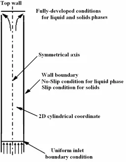
2.3.2 Boundary conditions
The computational domain of the riser is shown in Fig. 2.2. As it is seen, the uniform boundary conditions are imposed on the inlet of the riser for both solids and liquid streams. Therefore, the quantities of both phases are distributed uniformly at the entire inlet cross section. The no-slip and free-slip boundary conditions are used on the wall for liquid and solid phases, respectively. Johnson and Jackson (1987) developed the boundary conditions for the slip velocity of solid phase near the wall:
[
1 ( / )]
N tan 06 u 3 u n ). .( u f 3 / 1 max , p p max , p sl p p sl f c
sl + =
The first term on the left side of Eq. (12) denotes the stress within the solids flow
approaching the wall. Here, usl is the slip velocity between the particles and the wall, σc
and σf are collisional and frictional stress tensors, respectively, and n is the unit normal
vector of the wall. The second term stands for the rate of tangential momentum transfer to the wall by particle-wall collisions, which is the product of the collision frequency for
each particle, 3Θ/s, the average tangential momentum transferred per collision,
6 /
3
sl p p
π
d uφρ
, and the number of particles adjacent to unit area of the wall, 1/ac. Here, sdenotes the average distance between the wall and an adjacent particle, estimated by
(
)
[
,max / 13−1]
=dp p p
s α α , ac is the average boundary area per particle read as
(
)
23max ,
2 /
p p
p
c d
a = α α , and φ is the specularity coefficient. ρp is the density of the solid
material, dp is the particle diameter, Θ is the granular temperature, αp is the solids
volume fraction, and αp,maxis the solids volume fraction at a closely random packing
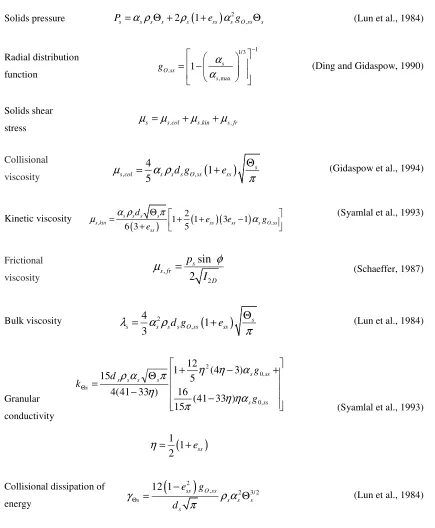
Table 2.1. The constitutive correlations for closure of the transport equations
Solids pressure
(
)
2,
2 1
s s s s s ss s O ss s
P =α ρ Θ + ρ +e α g Θ (Lun et al., 1984)
Radial distribution function 1 1/3 , ,max 1 s O ss s g α α − = −
(Ding and Gidaspow, 1990)
Solids shear
stress µs =µs ,col+µs ,kin+µs , fr
Collisional
viscosity , ,
(
)
4
1 5
s s col s sd gs O ss ess
µ α ρ
π
Θ
= + (Gidaspow et al., 1994)
Kinetic viscosity
( ) ( )( )
, ,
2
1 1 3 1
6 3 5
s s s s
s kin ss ss s O ss
ss d
e e g
e
α ρ π
µ = Θ + + − α
+
(Syamlal et al., 1993)
Frictional
viscosity , 2
sin 2 s s fr D p I φ
µ = (Schaeffer, 1987)
Bulk viscosity 2
(
)
,
4
1 3
s s s sd gs O ss ess
λ α ρ
π
Θ
= + (Lun et al., 1984)
Granular conductivity − + − + − Θ = Θ ss s ss s s s s s s g g d k , 0 , 0 2 ) 33 41 ( 15 16 ) 3 4 ( 5 12 1 ) 33 41 ( 4 15 ηα η π α η η η π α ρ
(
)
1 1 2 essη= +
(Syamlal et al., 1993)
Collisional dissipation of energy
(
2)
, 2 3/2
12 1 ss O ss
s s s s
s e g d γ ρ α π Θ −
The granular temperature of the solid phase near the wall is calculated based on the correlation by Johnson and Jackson (1987):
(
2)
3/22
, 2/3 2/3
,max ,max ,max ,max
2/3 2/3
3
1
0.
2 3
4
s
p sw s
p Slip s w
s s s s
s s s s
e
u
q
θπρ
ψ θ
πρ
θ
α
α
α
α
α
α
α
α
−
+
−
=
−
−
(13)
where uslip and qw,θs are the slip velocity and the flux of fluctuation energy within the
solids flow approaching the wall.
The standard k-ε model used for the liquid phase or mixture is only applicable for high
Reynolds flow. Therefore, the viscosity-affected near-wall region at which Re number is low is resolved by a near-wall model. In this study, the two-layer approach is used as a near-wall model to calculate the velocity, turbulence energy dissipation and the turbulent viscosity of the liquid phase or mixture in the near-wall region. Fully-developed flow condition is used for all flow quantities at the outlet of the riser. The flow is assumed to be axisymmetric to reduce computational cost.
2.4
Numerical methodology
The commercial software, ICEM CFD, Ansys 13.0, is used to create the riser geometry and then generate the mesh. The governing equations are then solved by the commercial CFD code FLUENT, Ansys 13.0. The convection terms and gradients in all transport equations are descritized by the second order upwind method and green-gauss cell based method, respectively. The SIMPLE algorithm using a segregated solution technique is used to solve the pressure field and velocity field. The mesh independence is examined using three different grids, 25×2500, 30×3000 and 35×3500. The radial distributions of the solid holdup at the height of 2.5 m obtained by these three grids are compared. The result from 30×3000 grid deviates less than 0.5% from the one using the finer mesh. Therefore, this mesh is used in the rest of simulations in this study. The time step independence test shows that the time step of 0.005 sec can satisfy the time step independency. The specularity coefficient (φ), restitution coefficient of interparticle
collisions and restitution coefficient of particle-wall collisions are 0.0001, 0.99 and 0.99, respectively.
2.5
Results and Discussion
The numerical model presented in this study is used to predict the flow field in the
LSCFB riser. The effect of turbulence models on the numerical simulation of the
liquid-solid turbulent flow is examined by comparing the numerical results with available
experimental data (Zheng et al., 2002 and 2003). Also, the effects of the liquid superficial
LSCFB riser are investigated. In addition, the residence time distributions (RTD) of both liquid and solid phases are determined under one of the operating conditions.
2.5.1 The effect of turbulence models
In order to investigate the influence of turbulence models on the numerical results of the
turbulent liquid-solid flow in an LSCFB, simulations are performed using three different
types of k-ε multiphase turbulence models, the mixture turbulence model, dispersed
turbulence model and per-phase turbulence model. The comparison between the numerical results using three different turbulence models and experimental data for the radial liquid velocity profiles is shown in Fig. 2.3 under Ul=0.1 m/sec and Gs=5 kg/m2sec at H=0.8 m above the inlet distributor of the riser.
Figure 2.3: Comparison of the liquid velocity profile using
three types of the k-ε multiphase turbulence models
It can be seen that the predictions using the dispersed and per-phase k-ε models are in
good agreements with the experimental data obtained by Zheng et al. (2003). In contrast,
the mixture k-ε model is not an appropriate model for the turbulent two phase flow in a
LSCFB, when the density ratio between the two phases is much higher than 1.
The comparison of the numerical prediction for the radial solids holdup profiles with the experimental data is shown in Fig. 2.4. It is seen that there is a slight difference among the solids holdup predictions using three different k-ε multiphase models.
Figure 2.4: Comparison of the solids holdup profile using three types of k-ε
multiphase turbulence models (Experimental data by Zheng et al. (2002)).