Close Loop Response of BLDC Motor by using
Hysteresis Current Control Technique
Shrey Kevat1, Gaurang Patel2
M.E., Dept. of EE, MGITER, Gujarat, India1
Asst. Professor, Dept. of EE, MGITER, Gujarat, India 2
ABSTRACT:For getting variable speeds, the brushless DC motors are the best to use in different application now a day. It has wide applications and more advantages over brushed DC motor. It gives better performance than the brushed DC motor. In this paper, a close loop speed response of three phase BLDC motor is mentioned. The results of different bandwidth are taken. In close loop test, the speed of the motor is been constant by speed controller. The Hall Effect sensors are used to sense the position of the rotor. Inverter is used to feed gate pulses to turn on the motor. The simulation of the close loop three phase brushless DC motor is done in MATLAB environment. Different results of simulation are shown in this paper.
KEYWORDS:Brushless DC Motors, Hysteresis Current Controller, Speed Controller
I. INTRODUCTION
Brushless DC motors are much demanded in many industries, in commercial areas and in domestic areas because they’ve variable speeds which are required in certain applications. The DC machines have been used quite few years because we didn’t have many options. Yes, BLDC motor is little expensive as compared to the induction motor and DC motors but at the end BLDC motor gives the best performances. In brushed DC machines, due to the presence of brushes and commutators, it becomes very expensive because it needs maintenance in regular intervals and these motors also have unreliable performances. Brush and commutator do sparking so it has degraded efficiency. This disadvantage led to make that motor which has higher efficiency and that motor is brushless DC motor. Brushless DC motor has many advantages like it has wide ranges of speeds, power ratings and torques, higher inertia; lesser the maintenance, higher efficiency, compact size, high torque & power density. The brushless DC motor has applications like robotic arm movement for industrial application, in space for projection of satellite panels, for actuators in aerospace applications, feed drives for the CNC machine. It has electronic commutation instead of mechanical commutation as it was in brushed DC machines. The BLDCM looks like a conventional DC motor because it also has a liner relationship between voltage & rpm and current & torque. In this motor, the armature windings are on the stator where as permanent magnets are on the rotor .Hall sensors are used to sense the position of rotor to start commutation between the stator and the rotor.
II. WHYCONTROLLERISSOIMPORTANTTOBLDCM
In close loop system, controllers are very important. Here in BLDC motor there are two controller is been used, 1st is current controller and 2nd is speed controller. There are two loops taking place in the close loop controlling, inner loop is been by current controller and outer loop is been by speed controller.
Once reference current is set, motor can reach up to desired speed and finally loop is been closed and error is been mitigated. Finally even in loaded condition we can get constant speed.
III.PRINCIPLE&STUCTUREOFBLDCMOTOR
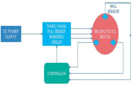
The block diagram of BLDCM can be divided into three main parts:
Inverter
Controller
BLDC Motor
Controller is further divided into two parts as mention above, current controller and speed controller. BLDCM has hall sensors placed on it.
Fig 1: Block diagram of BLDC Motor
Brushless DC motor is synchronous type motor so it doesn’t have slip as it is in induction motors. It has two magnetic fields, once rotor magnetic field & second stator magnetic field. The Hall Effect sensors sense the position of rotor and on the basis of which pole nearer to it; it gives low and high signals and sends signals to inverter. When an inverter gets those signals, it switches on and energizes any two windings from the stator and winding behaves as solenoid. Because of attraction between two magnetic fields, torque generates and rotor starts to rotate. Electronic commutation is been used instead of brushes and commutators for commutation. The switches of inverter conduct for 1200 and after every 60 degree phase conduction changes to keep motor moving. The block diagram of the open loop BLDCM is shown in figure 1.
As shown in figure, the hall sensors sense the position of rotor and according to that it sends signals to controller. Furthermore the controller generates pulses which are fed back to inverter. Inverter us supplied by a DC source of 36V. The inverter energizes any two phases of the motor and after that, the motor runs.
Inverter
Speed Controller
Speed controller is shown as below.
Fig 2 Speed controller
Speed controller consists PI controller and subsystem of current controller. Here reference speed is set as of 3000 rpm and actual speed is been compared with reference speed and error sends to the PI controller so that it mitigates an error and give us the desired speed. Once we get the desired speed we can set the reference torque to get the reference current.
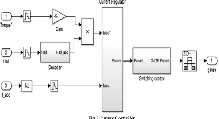
Current Controller
Here in current controller three values are injected as shown below. Reference torque is multiplied with hall sensor’s signals to be in phase with back emf and because of multiplication of these two we cwn get reference current. And actual current is been injected.
Fig 3 Current Controller
Hysteresis Current Controller
Here as shown in the figure, two currents are been compared and error sends back to the hysteresis band which is given.
Fig 4 Hysteresis Current Controller
Here there are 3 phases. All positive phases of reference currents and negative phases of actual currents are combined. For example reference current for phase A and actual current for phase A is been compared. After that, an error is been provided to the hysteresis band where it is been mitigated and we get the desired current and fed to the switching pulse block.
IV.SIMULATIONANDRESULTS
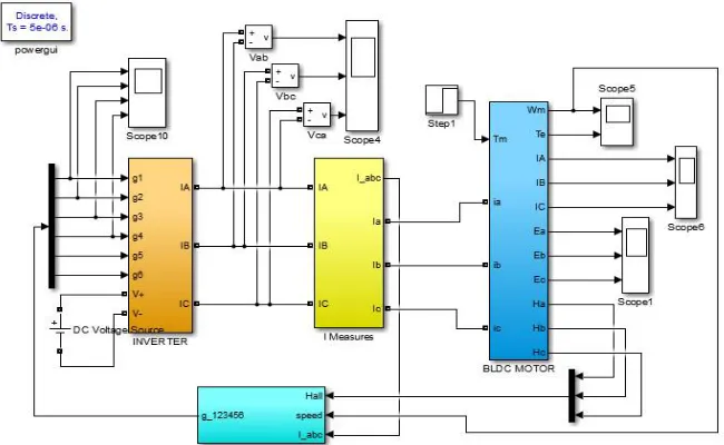
The close loop simulation of motor is shown as below.
As shown in figure, the simulation is exactly looking like its block diagram as mention above. It has mainly four blocks like an inverter block, I measures, BLDC motor block and speed controller. Inverter is supplied by 36 DC voltages. BLDC consists of current and back emf of 3 phases. It also consists torque and speed of motor under loaded condition. Hall signals come from the motor and fed back to the speed controller block. Actual current is been measured in current measurement block and it fed to speed controller block. Speed of the motor at loaded condition as well fed to the controller block. Gate pulses are the result of the controller block and it feds to inverter to switch on any two switches from 3 phases. So this is how close loop working is been completed.
Table 1: Parameter values for BLDCM
Stator phase resistance 1.5 ohm Stator phase inductance 4.2 mH
Flux linkage 0.1575 V.s
Voltage constant 6.5973 V_peak L-L / krpm
Torque constant 0.063 N.m / A_peak Back emf flat area 120 J(kg.m^2) F(N.m.s)
p() Inertia, friction factor,
pole pairs
[0.75e-5 2.045e-4 2]
Voltage 36 V
Speed 4000 rpm
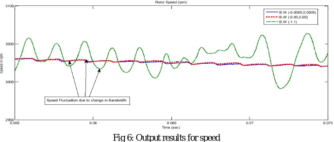
After taking these values we simulate the circuit and get the result as shown below. 36 V is applied as an input and its rated speed is 4000 rpm.
Fig 6: Output results for speed
The above waveform shows the output of the speed for different bandwidths. It shows total three output waveforms. First blue colour shows for the bandwidth of 0.0005, for this speed is constant. Second red colour shows for the bandwidth of 0.05, for this speed is fluctuated than rated. Third green colour shows for the bandwidth of 1, for this speed is more fluctuated.
V. CONCLUSION
bandwidth of ±0.05 and ±1 speed curve will fluctuated. Also electromagnetic torque and stator current waveforms are distorted by changing bandwidth of hysteresis band. This can be happen because of in hysteresis current control method switching of inverter switches can depends on hysteresis band. Drawback of decreasing in bandwidth is that it can increase the switching losses.
REFERENCES
[1]. TM Shubhum and Dr. AmitOjhaPramod Pal, "Simulation of Brushless DC Motor for Performance Analysis using MATLAB/SIMULINK Environment," International Journal on Recent and Innovation Trends in Computing and Communication”, vol. 2, no. 6, pp. 1564-1567, june 2014. [2]. Sergio Andres Reyes Sierra, "Switching Techniques for Brushless DC Motors," IEEE, pp. 4673-6155, FEBRUARY 2013.
[3]. Pallav Dutta, Santanu Kumar Nayak, "A Comparative Study of Speed Control of D.C. Brushless Motor Using PI and Fuzzy Controller," in IEEE, 2015.
[4]. Yogesh Pahariya, Aditya Tiwary, RakeshSaxena, "Modeling and Simulation of BLDC Motor Using Soft Computing Techniques," in IEEE, 2010.
[5]. Pabitrakumar biswas, atanu banerjee, Chiranjit Sain, "Design and Analysis of open loop model of a Permanent Magnet Synchronous Motor (PMSM) Drive," in IEEE, 2015.
[6]. Min-Yi Wen, and Ching-Chang Wong Han-Chen Wu, "Speed Control of BLDC Motors Using Hall Effect Sensors Based on DSP," IEEE, vol. 2, pp. 7-9, JULY 2016.
[7]. Caroline annsam, Tony Mathew, "Closed Loop Control of BLDC Motor Using a Fuzzy Logic Controller and Single Current Sensor," International Conference on Advanced Computing and Communication Systems (ICACCS), December2013.
[8]. Archana garg, Madhusudan Singh, "Performance Evaluation of BLDC Motor with Conventional PI and Fuzzy Speed Controller," IEEE, 2012.