277 | P a g e
COMPARISION OF PLAN IRREGULARITY OF
MULTISTORIED SHEAR WALL STRUCTURE FOR
WIND ANALYSIS
Akash S. Waghmode
1, D. N. Kakade
2, Dr. A.P. Wadekar
3 1PG Student, Department of Civil Engineering, P.E.S College of Engineering,
Nagsenvan Aurangabad, Maharashtra, (India)
2
Assistant Professor, Department of Civil Engineering, P.E.S College of Engineering,
Nagsenvan Aurangabad, Maharashtra, (India)
3
Principal P.E.S.College of Engineering, Aurangabad, Nagsenvan Maharashtra,(India)
ABSTRACT
In this new era of structural advancement there is scope to go for betterment in terms of utility, feasibility and
economy of structure.As we know India is the most populous country by 2022 keeping behind China. So there is
need to grow in verticality due to scarcity of space in urban areas For the multistory structure the challenge is
to make it feasible in terms of lateral load due to wind and earthquake which prominently dominates the
structure .However in this study we decided to focus on shear wall structures ,because it is widely known that
shear walls help in improving the performance of structure when it is subjected to lateral loads by enhancing
the strength and stiffness to study performance of structure we are comparing plan regularity and irregularity
for the same configuration of its Area, Height, and Topography for drift and displacement.
Keywords: E-TABS, Plan irregularity, Story displacement, Story drift, Shear wall.
I INTRODUCTION
In India due to variability of topography which comes in different zones for wind which is most important
parameter while considering the high rise building. A large portion of India approximately 60% of land is
susceptible for cyclones, floods, earthquakes and landslides etc.Due to industrial policy most of the industries
are situated near by the urban areas, hence much of the population is concentrating in this area. Because of this
occurrence of scarcity of space is big issue.Keeping these issues in consideration concept of multi-storied
structure comes into the picture. The response of wind effect becomes critical issue to find effective disaster
mitigation technique, so that building remains in acceptable function during disaster.
As height increases the effect of lateral load due to wind increases, Inpresent study building with different plans
are modeled for same height and area with shear wall in it. To know to effect of wind for irregular plan so as to
278 | P a g e
1.1
Wind
Wind loads is considered as per IS 875-1987 (Part 3). In this paper wind speed varies with location and depends
on several factors such as density of observation in terrain, size of gust, return period, and probable life of
structure. In Wind load cause dynamic action whose fundamental frequency of vibration will be less than 1 Hz.
Wind speed in general influenced by a local topography.
1.2 Shear Wall
Various studies over world have proved shear wall one of the most preferred lateral load resisting system.
Considering mass center and centroid is ideal configuration, to avoid torsional effect there should be
symmetrical placement of shear wall. Shear wall of varying cross section i.e. rectangle shape to more irregular
core such as channel ,T,L, Barbell shape etc. although past researcher studied different configuration of shear
walls but there is still a scope to improve drawbacks in multistory structure for wind effect.
1.3 Literature review
Md. Rashduel , DebasishSen(1)Presented the work on regular and irregular shape building of identical weight
under static and dynamic loading .They have studied various shapes and they found that maintain the total mass
content ,it is possible to construct an irregular shaped building which might have irregular shape building which
might behave more like rectangular building .
AbhayGuleria (2) presented the earthquake lateral load effect on high rise building system as per (IS 1893: part
1:2002). The modelling and analysis carried out by ETABS and different plan configuration found that, L-shape
and I-shape structure perform same in overturning moment, story drift and story displacement in earthquake
analysis, study also involves the shape importance in effect of earthquake prone zone.
Aneeket T. patil ,Sachin B. Kadam (3) They have studied Behavior of multistoried building under effect of wind
and earthquake for different combination of shear wall .They have observed that after G+10 structure wind is
more prone for the drift in structure
M. Pavini, G. Nagesh Kumar ,Dr.Sandeeppingale (4)Presented the study on shear wall analysis and design
optimization in case of high rise building .They have studied the story stiffness ,Base shear and displacement
and analysis is compared.
1.4
Objective of Studies
a. To study the behavior of structure for regular plan and irregular plan for wind loads
b. To evaluate response of RC building with shear wall at periphery of structure
c. To know the story drift of symmetric building with respect to unsymmetrical building for same area
279 | P a g e
II SYSTEM DEVLOPMENT
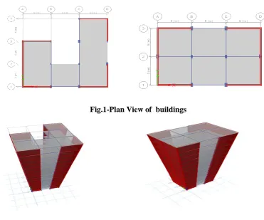
In this analysis RCC G+15 J shaped and rectangular shaped structure have analysed .The shear wall location is
adopted in L shape at all corners .The total building system of J shaped and rectangular shape is analysed using
Etabs 2015 software.
Fig.1-Plan View of buildings
Fig2-3D view of J shape and Rectangular shape
Wind load are considered using provision made by IS 875:1987 (part 3) in addition to this load envolops are
considered by IS 875 (part5).Building section and shear wall section is desinged by IS456:2000 and
IS13920:1993 and checked for failures in ETab . After analysing the G+15 model following results are obtained.
Table 1:General Specification Table 2: Material Specification
Sr. no.
General specification Values/sizes
1 Plan dimension 150m2
2 (G+15) 52.1
3 Floor to floor height 3.1m
4 Bottom storey height 2.5m
5 Thickness of wall 230mm
Sr
no.
Material properties Value
1 Grade of concrete M30
2 Grade of steel Fe425
3 Density of concrete 25KN/m3
4 Density of brick 20KN/m3
280 | P a g e
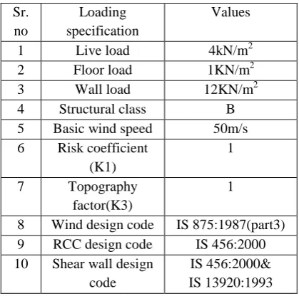
Table 3: Loading Specification
Table 4: Shear wall specification
Table 5: RCC Rectangular specification Table 6: RCC J shape section
III RESULT AND DISCUSSION
The story displacement in X direction is found to be maximum and particular in case of RCC J shaped G+15
structure .Both the model have corner L shape shear wall provision ,though the displacement in RCC
rectangular G+15 structure is minimum. Rectangular structure has regular geometry that’s why its surface is
resistive in nature and found out to be stable in wind prone zone. Sr.
no
Shear wall
specification
Values/sizes
1 Design of shear wall General R/f
2 Thickness of shear
wall
230mm
3 Corner bar size 16mm
4 General bar size 6mm
5 Spacing between bar 300mm Sr.
no
Loading specification
Values
1 Live load 4kN/m2
2 Floor load 1KN/m2
3 Wall load 12KN/m2
4 Structural class B
5 Basic wind speed 50m/s 6 Risk coefficient
(K1)
1
7 Topography factor(K3)
1
8 Wind design code IS 875:1987(part3) 9 RCC design code IS 456:2000 10 Shear wall design
code
IS 456:2000& IS 13920:1993
Sr no. RCC section
1 Beam 300X600
Column up to 8 story
2 Column1 230X450
3 Column2 300X600
4 Column3 350X700
Column from 8 story to 17 story
5 Column4 400X800
6 Column5 500X700
7 Column6 500X900
Sr
no.
RCC section
1 Beam 300X530
Column up to 8 story
2 Column1 500X900
3 Column2 300X700
4 Column3 500X700
Column from 8 story to 17 story
5 Column4 450X800
6 Column5 400X700
281 | P a g e
Fig.3- Story displacement in X direction for G+15 Structure
After comparing the story drift for G+ 15 RCC Rectangular and J shape, Rectangle shape has less story drift
than J shape. The story drift is calculated in X direction for both the structure. Therelativestory displacement is
greater in J shape that’s why story drift in J shape is greater.
Fig.4- Story drift in X direction for G+15 Structure
IV CONCLUSION
1]
In RCC structure shear wall is provided for optimizing the section, Displacement, Drift.2] The study result shows two same plan area structures having different parametric change in which rectangular
structure in wind prone zone is preferred.
3] As the story height of both J shape and rectangular shape is same but still the displacement and drift in J
shape is more.
4] As we see the J shape is irregular structure hence need to be analysed for special provision for windlateral
282 | P a g e
ACKNOWLEDGEMENT
I wish to acknowledge the support of Prof.D.N.Kakade,Dr.AbhijeetWadekarPrincipel of P.E.S college ,H.O.D
of civil engg.DeptDr.R.M.Sawant and Prof R.D.Pandit I am grateful to P.E.S college of Engineering
Aurangabad. For supporting this study and made all arrangement required for study.
REFERENCES
[1] AmbadkarS. BawnerV., “Behavior of multistoried building under the effect of wind load”, International
journal of applied science and engineering research, vol.1 (2012)
[2] HirdeS.,MagadumV., “Severity of Earthquake Force against Wind Forces and Multistory RCC
Building” IOSR Journal of mechanical and Civil Engineering (IOSR-JMCE) pp.71-75(2014)
[3] Kijewski T. and Kareem A., “Full Scale Study of Behavior of Tall Buildings Under winds” Health
Monitoring and Management of civil ,SPIE Vol.4337(2001)
[4] IS: 456(2000), Indian Standard Code of Practice for Plain and Reinforcement concrete (Fourth Revisions),
Bureau of Indian Standards (BIS), New Delhi
[5] IS: 875(Part 3)-1987, Indian Standard Code of Practice for Design loads (other than Earthquake) for