1915 | P a g e
Effect of Keyways in the Design of Drive Shaft: A Case
Study
1
Swati Verma,
2S.K.Srivastava
1
PG Student, MED, M.M.M.U.T. Gorakhpur-(UP), India
2
Professor, MED, M.M.M.U.T. Gorakhpur-(UP), India
ABSTRACT
The discontinuity in shaft arises due to the presence of keyway, groove, crack, etc. The objective of present work is
to study the deformation, equivalent stresses and maximum shear stresses generated in the circular solid shaft and
hollow shaft in the presence of keyways (rectangular, square and tapered), keeping the volume of material constant.
The effects of different shaped keyways present in the solid shaft are studied as regards to their deformation,
equivalent stresses and maximum shear stresses under the action of applied torque. The 3D modeling and analysis
of drive shaft with and without keyway is carried out using ANSYS software. It is concluded that rectangular keyway
is best from the design point of view of solid shafts.
Keywords: Torque, Moment, Keyway, Finite Element Analysis, Keyway.
I INTRODUCTION
Drive
shaft is generally used in automobiles for the transfer of rotary motion and torque to the differential usinghelical gear box which results motion of the rear wheels. Fig. 1 shows the application of drive shaft in automobiles.
The wide applications of drive shaft, consisting of structural steel, reflect in automobile world like, buses, trucks,
aero planes, etc. [9]. Failures of shafts not only result in replacement cost, but also in process downtime. This could
have a drastic effect on the productivity and, more importantly, late delivery. It had been found that the downtime
was 3 days, and 1,800 metric tons of steels were lost before the failed shaft could be replaced [7].
The failure of drive shaft may result from many reasons including improper designs, manufacturing errors or
improper applications. Design errors include selection of poor quality or wrong materials, improper gear geometry,
inappropriate lubrication system, etc. whereas improper mounting and installation, inadequate lubrication, poor
cooling, and poor maintenance lead to application errors. Manufacturing errors could be poor machining or
inaccurate heat treatments of drive shafts leading to poor mechanical properties [13].The shaft may fail due to the
discontinuity present in the shaft such as keyway. They are generally used to connect shaft with hubs. These are
available in several shapes such as rectangular, square, tapered, woodruff, etc. and its design is fully controlled by
1916 | P a g e
The inclusion of keyways in the drive shaft leads to complex cross-section leading to stress concentrations at the
sharp corners. The effect of mechanical loading on complex cross-section can be more accurately analyzed using
Finite Element Analysis (FEA). FEA is a method of solving, usually approximately, certain problems in engineering
and science which does not provide exact solution. The method is applied if either shape or loading on the
component is complex. The method is applied to the problems involving a wide range of phenomena, including
vibrations, heat conduction, fluid mechanics and electrostatics, and a wide range of material properties, such as
linear-elastic behaviour and behaviour involving deviation from Hooke's law [6].
Figure 1: Application of drive shaft in automobiles [11]
In the present work, solid and hollow drive shafts incorporating different types of keyways is analyzed using FEA
and deformation, equivalent stresses, maximum shear stresses are calculated at critical locations keeping volume of
solid and hollow shaft constant. The results are compared for solid and hollow shaft considering keyways of
different shapes.
II ANALYSIS OF DRIVE SHAFT
The c
ircular solid and hollow drive shaft with and without keyways (rectangular, square and tapered) is modeledand analyzed in ANSYS software and deformation, equivalent stress and shear stress distributions in drive shafts are
investigated as a case study for the following material properties [12]:
The density of material (structural steel): Poisson’s ratio: 0.3, Young modulus: 207 GPa and shear modulus: 80GPa.
The shaft analysis is carried out under the following assumptions [4, 8]:
It rotates at a constant speed.
The shaft has a uniform circular cross section.
The stress-strain relationship for steel material is linear and elastic.
All damping and non linear effects are excluded.
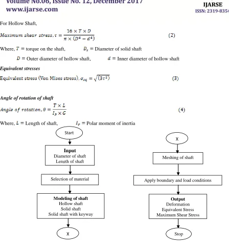
Maximum shear stresses
1917 | P a g e
For Hollow Shaft,
Where, torque on the shaft, Diameter of solid shaft
Outer diameter of hollow shaft, Inner diameter of hollow shaft
Equivalent stresses
Angle of rotation of shaft
Where, Length of shaft, Polar moment of inertia
Figure 2: Flowchart for calculation of deformation and stresses in drive shaft
The 3D modeling of solid and hollow shaft and FEA is carried out in ANSYS 16.2 for the following dimensions:
Outer diameter, D= 80 mm, Inner diameter, d = 50 mm, Length, L=1000 mm [12]. The diameter of solid shaft is
determined by equating it’s volume to volume of hollow shaft. Thus, diameter of solid shaft = 62.5 mm. The
rectangular keyway dimensions are [5]: width =18 mm, depth = 7 mm and length = 140 mm.
Start
Input
Diameter of shaft Length of shaft
Modeling of shaft
Hollow shaft Solid shaft Solid shaft with keyway
Selection of material
X
Meshing of shaft
Apply boundary and load conditions
Output
Deformation Equivalent Stress Maximum Shear Stress
1918 | P a g e
Figure3: Load and boundary conditions of solid shaft with rectangular keyway
After modeling, the mesh is generated using tetrahedron with element size of 4 mm, no. of nodes 265668 and no. of
elements 76762. The hexahedral element consists of 20-nodes with three degrees of freedom at each node capable of
translation in x, y and z nodal direction. Fig. 3 shows load and boundary conditions of solid shaft having rectangular
keyways. One end of the shaft is fixed and torque (3500 N-m - 4500 N-m) is applied at the free end [12].Similar
boundary conditions are used for hollow/solid shafts with/without keyways.
III RESULTS AND DISCUSSION
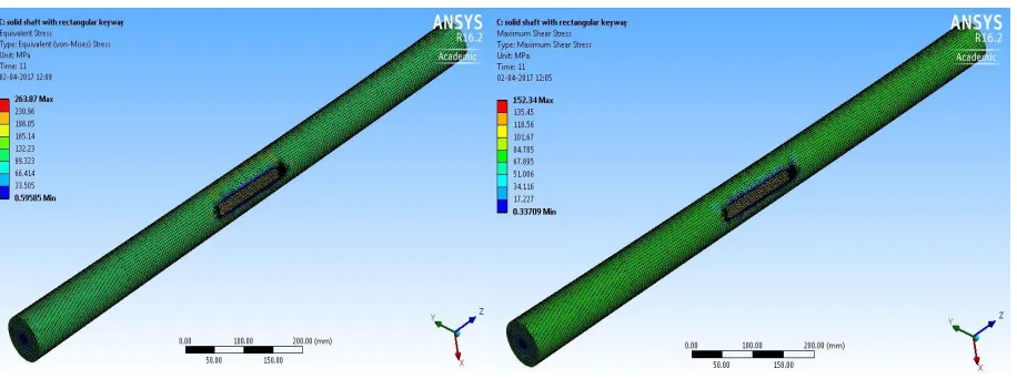
Figs.4&5 shows equivalent stresses and maximum shear stresses induced in the solid shaft with rectangular
keyways. Fig. 4 shows the equivalent stresses in the solid shaft with rectangular keyway with minimum at the centre
and maximum at the edge of rectangular keyway. Fig. 5 shows the maximum shear stress in the solid shaft with
keyway with minimum at the centre and maximum at the edge of keyway.
Figure 4: Equivalent stress in solid shaft with rectangular Figure 5: Maximum shear stress of the solid shaft with
1919 | P a g e
Fig. 6 shows the variation of deformation with torque applied for different types of shaft. As expected, the
deformation increases with increase in torque value; however, it is less in solid shaft as compared to the hollow
shaft. Discontinuity (keyway) in solid shafts increases the deformation in the order: tapered > square > rectangular.
Figure 6: Effect of torque on deformation for different types of shaft
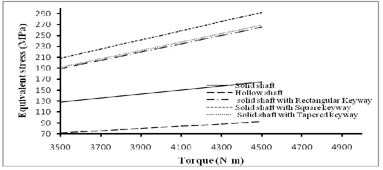
Fig. 7 shows the variation of equivalent stresses generated in different types of shaft. As expected, the equivalent
stresses increases with an increase in torque applied. The stresses in hollow shaft are less as compare to solid shaft.
Discontinuity (keyway) present in the shaft increases the equivalent stresses. The equivalent stresses in solid shaft
with rectangular keyway are minimum as compared to the square/tapered keyways.
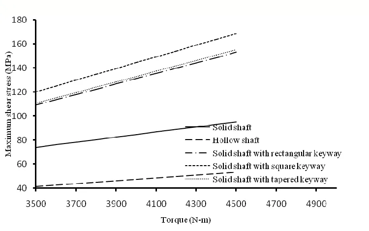
Fig. 8 shows the variation of maximum shear stresses generated with torque in different types of shaft. As expected,
the maximum shear stresses increases as torque increase. The stresses in hollow shaft are less as compared to the
solid shaft and discontinuity (keyway) in the shaft increases the maximum shear stresses. The stresses with
rectangular keyway are minimum as compared to the other keyways.
1920 | P a g e
Figure 8: Effect of torque on maximum shear stress generated in different shaft with and without keywaysTable 1 shows comparison between the solid and hollow shafts as regards to the deformation, equivalent stresses
and maximum shear stresses at 4500 N-m torque. Table 2 shows the deformation, equivalent stresses and maximum
shear stresses in solid shafts with different shapes of keyways such as rectangular, square and taper at 4500 N-m
torque. It is concluded that rectangular keyway is best from the design point of view of solid shafts.
Table 1: Deformation, Equivalent stresses and Maximum shear stresses in solid and hollow shafts
Parameters Solid shaft Hollow shaft
Deformation, mm 1.22 0.6868
Equivalent stresses, MPa 165.1 92.34
Maximum shear stresses, MPa
95.319
53.307
Table 2: Deformation, Equivalent stresses and Maximum shear stresses generated in solid shafts
with different shapes of keyways
Parameters Solid Shaft with
rectangular keyway
Solid shaft with
square keyway
Solid shaft with
tapered keyway
Deformation, mm 2.25 2.26 2.17
Equivalent stress, MPa
265.13
292.08
268.8
1921 | P a g e
IV CONCLUSIONS
The design and analysis of hollow and solid drive shafts with/without keyways is carried out in ANSYS software.
For given dimensions of the shaft, the following conclusions are drawn from the total deformation, equivalent
stresses and shear stresses distribution in the shaft:
1) The total deformation in hollow shaft is less as compared to the solid shaft in the absence of keyway.
However, the deformation in solid shaft with keyways is more as compared to the solid shaft. Discontinuity
(keyway) in solid shafts increases the deformation in the order: square > tapered > rectangular.
2) The equivalent stresses in shafts are maximum at the outer surface and minimum at the inner surface. The
equivalent stresses in hollow shaft are approximately 44% less as compared to the solid shaft, if volume
remains same. The equivalent stresses are least in solid shaft the presence of rectangular keyway.
3) The maximum shear stress is maximum at the outer surface and minimum at the inner surface. The
maximum shear stress in hollow shaft is approximately 44% less as compared to the solid shaft, if volume
remains same. The maximum shear stress is least in solid shaft in the presence of rectangular keyway.
It is concluded that rectangular keyway in solid shaft is best as far as the total deformation, equivalent
stresses and shear stresses generated is concerned.
REFERENCES
[1]. Jong, Ing-Chang, and William Springer. "Teaching von Mises Stress: From Principal Axes To Non-Principal
Axes." American Society for Engineering Education. American Society for Engineering Education, 2009.
[2]. Pedersen NL. Optimization of keyway design. In Proceedings of the 2nd International Conference on
Engineering Optimization (+ cd-rom) 2010 Jan 1.
[3]. Bhandari, V. B., Design of Machine Elements. Tata McGraw-Hill Education, 2010.
[4]. Khurmi, R. S., and J. K. Gupta, Machine Design. S. Chand, 2010.
[5]. Jadon, Vijay Kumar, and Suresh Verma. Machine design data book. IK International, 2011.
[6]. Szabó, Barna, and Ivo Babuska, Introduction to finite element analysis. John Wiley and Sons, 2011.
[7]. Moolwan C, Netpu S. Failure analysis of a two high gearbox shaft. Procedia-Social and Behavioral
Sciences, 2013 Oct 10; 88:154-63.
[8]. Parshuram D, Mangsetty S. Design and Analysis of Composite/Hybrid Drive Shaft for Automotives. The
International Journal of Engineering and science. 2013;2(01):160-71.
[9]. Kaviprakash G, Lawrence ID, Regan AP. Design and Analysis of Composite Drive Shaft for Automotive
Application. International Journal of Engineering Research and Technology, 2014 Nov 11, Vol. 3
[10]. Ravi A. Design, Comparison and Analysis of a composite Drive Shaft for an Automobile. International
1922 | P a g e
[11].Sulthana PP, Aruna K, Rao TK, Shivakumar HG. Design and analysis of drive shaft for heavy duty truck.
International Journal of Engineering Research and Technology, 2015 Feb 02, Vol. 4
[12].Ganesan, M., S. Johny James, and P. Santhamoorthy. "Design to Replace Steel Drive Shaft in Automobiles
with Hybrid Aluminium Metal Matrix Composite." Journal of Advance in Mechanical Engineering and
Science, Vol. 1 (3), 2015, pp. 41-48
![Figure 1: Application of drive shaft in automobiles [11]](https://thumb-us.123doks.com/thumbv2/123dok_us/7784731.1287393/2.612.180.436.241.336/figure-application-drive-shaft-automobiles.webp)