Indirect Vector Control of Induction Motor using ANN
Estimator and ANFIS Controller
Sanjaya Kumar Sahu
Department of Electrical Engineering Bhilai Institute of Technology
Durg - 491001
D. D. Neema
Department of Electrical and Electronics Engineering Chhattisgarh Institute of Technology
Rajnandgaon - 491445
T.V. Dixit
Department of Electrical and Electronics Engineering Bhilai Institute of Technology
Durg - 491001
ABSTRACT
This paper proposes the neural network solution to the indirect vector control of three phase induction motor including an adap-tive neuro fuzzy controller. The basic equations and elements of the indirect vector control scheme are given. The proposed con-trol scheme is realized by an adaptive neuro-fuzzy concon-troller and two feed forward neural network. The neuro-fuzzy controller in-corporates fuzzy logic algorithm with five layer artificial neural net-work (ANN) structure. The conventional PI controller is replaced by adaptive neuro-fuzzy inference system (ANFIS) which tunes the fuzzy inference system with hybrid learning algorithm. The two feed forward neural network are used as estimator, learned by the Levenberg-Marquardit algorithm with data taken from PI control simulations. The performance of proposed scheme is investigated at different load and speed conditions. The result of the proposed scheme are compared with PI controller. The simulation study in-dicates the robustness and suitability of drive for high performance drive applications.
Keywords:
Adaptive Neuro-Fuzzy Inference System(ANFIS), Artificial Neural Network (ANN), Back propagation algorithm, Hybrid learning algorithm, PI controller, Fuzzy logic controller(FLC),
1. INTRODUCTION
Three phase induction motors are widely used in the indus-trial world because they are economical and immune to heavy overloads. However the use of induction motor has its disad-vantages, mainly the controllability, due to its complex mathe-matical model and its non-linear behaviour [2]. The vector con-trol or field oriented concon-trol (FOC) theory is the base of a spe-cial control method for induction motor drives. With this the-ory induction motor can be controlled like a separately excited dc motor.This method enables the control of field and torque of the induction machine independently (decoupling) by manipulat-ing the correspondmanipulat-ing field oriented quantities. There exist two methods for PWM current controlled inverter - direct and rect vector control [16, 2, 8] . This paper will consider the indi-rect control method, where the slip angle, the diindi-rect and quadra-ture axes stator current set point components in synchronous ref-erence frame are computed from the torque and rotor flux set points and used for vector control.There are several papers of
neural network application for indirect vector control drive. In [3] a feed forward neural network and back propagation learning are used for angular velocity estimation and control of induc-tion motor using only stator current measurement. The paper [7] present a method of neural network velocity estimation and in-duction motor control based on flux, voltage, and current models. In [14] a neural controller is implemented based on TMS320C30 microprocessor in order to emulate an indirect vector control of an induction motor drive. There are several papers of fuzzy logic application for indirect vector controlled induction motor drives. In [11] a fuzzy learning enhanced speed control of an indirect vector control of induction motor drive is proposed. In [12] the performance of fuzzy logic controller has been investi-gated and compared with the conventional PI controller at differ-ent operating conditions. The paper [6] proposes a model refer-ence adaptive scheme in which the adaption mechanism is exe-cuted using a PI controller and fuzzy logic. In paper [15] a com-plete vector control scheme of induction motor incorporating the fuzzy logic controller has been successfully implemented in real time using digital signal processor controller board DS1102. A proportional-integral and fuzzy logic speed controllers operating in indirect field orientation [13] are designed and compared un-der no load and various load conditions with different reference speeds.
train-ing the ANN estimator and ANFIS controller is obtained by sim-ulation of the closed loop system with PI controller.
2. MODELLING
2.1 Induction motor modelling
The mathematical model of a three phase squirrel cage induction motor in synchronous rotating reference frames is given by the following equations [16, 2, 8]
Ve
ds = Rsieds+pλ e
ds−weλeqs (1)
Vqse = Rsieqs+pλ e
qs+weλeds (2)
0 = Rriedr+pλedr−(ωe−ωr)λpqr (3) 0 = Rrieqr+pλ
e
qr+ (ωe−ωr)λedr (4) Where
λe
ds = Lsidse+Lmidre (5)
λeqs = Lsiqse+Lmiqre (6)
λe
dr = Lridre+Lmidse (7)
λeqr = Lriqre+Lmiqse (8)
and electromagnetic torque
Te = 3 2
P
2Lm(i e qsi
e dr−i
e dsi
e
qr) (9)
ωr =
dθr
dt (10)
Te = jm
dωr
dt +Bmωr+Tl (11)
2.2 Indirect Vector Control
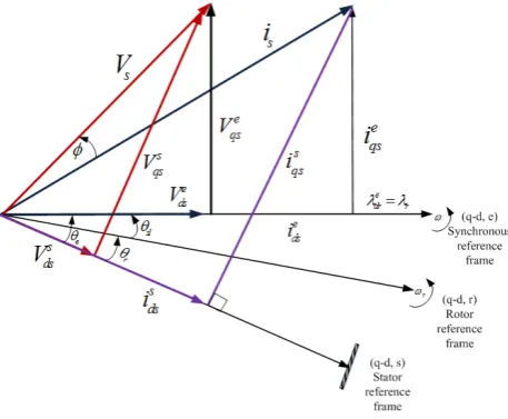
[image:2.595.315.547.458.543.2]The indirect vector control is a technique that controls the dy-namic speed of Induction motor.Unlike direct vector control, in indirect vector control, the unit vectors are generated in an in-direct manner. Figure(1) explains the fundamental principle of
Fig. 1. Phasor diagram of Indirect vector control principle
indirect vector control with the help of phasor diagram. Theds
-qs axes are fixed on the stator anddr-qr axes are fixed on the rotor which rotate at a speedωr . Synchronously rotating axes
de-qeare rotating ahead ofdr-qraxes by the positive slip angle
θslcorresponding to slip frequencyωsl. Thus
θe= Z
ωedt= Z
(ωr+ωsl)dt (12)
For decoupling controlλqr = 0orpλqr = 0andλr =λdr. Substituting the above condition in (3), (4), (7) and (8)
ωsl =
RrLmieqs
Lrλr
(13)
Te = 3 2 P 2 Lm Lr
λrieqs (14)
ieqs = 2 3 2 P Lr Lm Te λr (15) ie ds = 1 Lm [λr+
Lr
Rr
pλr] (16)
3. STATOR CURRENT SET POINT ESTIMATION
The equations (13 - 16) are necessary and sufficient condition to produce an adequate field orientation. This conditions could be propagated to the set point variables.
ω∗sl =
RrLmie ∗ qs
Lrλ∗r
(17)
ieqs∗ = 2 3 2 P Lr Lm
Te∗
λ∗ r
(18)
ie∗ ds =
1
Lm [λ∗
r+
Lr
Rr
pλ∗
r] (19)
If we accept that the rotor flux set point is constant and its deriva-tive is zero, the above equation is simplified as
ie∗ ds=
λ∗ r
Lm
(20)
Using the above equations a general block diagram of indirect vector control of induction motor drive is as shown in figure(2).
It contains three principal blocks. They are
Fig. 2. General block diagram of indirect vector control of Induction motor
G1→Block of speed controller
G2→Block of estimation ofie∗ ds,ie
∗ qsandω
∗ sl
G3 →Block of current co-ordinate transformation(q, d, e)to (a, b, c)
4. PROPOSED SCHEME
4.1 Block of speed controller
The speed controller blockG1is proposed to be a neuro-fuzzy controller (ANFIS) which incorporate fuzzy logic algorithm with a five layer artificial neural network structure [1, 4] . The num-ber and shape of each memnum-bership function related to the input variables can be obtained in an optimized way from data sets of inputs and output associated with a training algorithm.
The speed error and the rate of change of actual speed error are the inputs of the neuro-fuzzy controller which are given by
Input1=εω=ω∗−ω (21)
[image:2.595.54.283.489.677.2]Whereω∗
is the command speed.
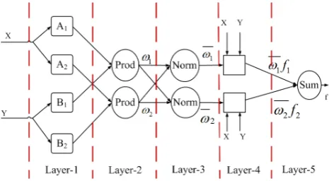
[image:3.595.53.286.190.318.2]First order Sugeno fuzzy model with five layer ANN structure [5] is used in proposed controller. In this five layer ANN struc-ture the first layer represents inputs, the second layer represents fuzzification, the third and fourth layer represent fuzzy rule eval-uations and the fifth layer represents de fuzzification. A two in-put first order Sugeno fuzzy model with two rules is depicted in figure(3).
Fig. 3. ANFIS architecture of 2-input Sugeno fuzzy model with 2 rules.
Layer 1.
Every node i in this layer is an adaptive node with node function
O1i=µAi(x)for i =1,2 or
O1i=µBi−2(x)f ori= 3,4 (23)
where x(or y) is the input node i andAiorBi−2 is a linguistic
label associated with this node. ThereforeO1iis the membership grade of a fuzzy set(A1, A2, B1, B2). In the proposed scheme generalized bell function is used as membership function given by
µA(x) = 1 1 +|x−ci
ai |
2bi (24)
whereai, bi, ciare premise parameter set.
Layer 2.
Each node in this layer is a fixed node labelled prod whose output is the product of all incoming signals.
O2i=wi=µAi(x).µBi(y), i= 1,2 (25)
Each node output represents the firing strength of a rule.
Layer 3.
Each node in this layer is a fixed node labelled Norm whose out-puts are normalized firing strength given by
O3i=wi=
wi
w1+w2
, i= 1,2 (26)
Layer 4.
Every node in this layer is an adaptive node with a node function given by
O4i=wifi=wi(pix+qiy+ri) (27)
where wi is normalized firing strength from layer 3 and (pi, qi, ri)is the consequent parameter set of this node.
Layer 5.
A single fixed node is in this layer labelled Sum which computes the overal output as the summation of incoming signals.
O5i= X
i
wifi= P
iwifi P
iwi
(28)
Hybrid learning algorithm is used in proposed controller [5]. It has two passes, forward pass and backward pass. In the forward pass of hybrid learning algorithm, node output goes forward until layer 4 and the consequent parameters are identified by the sequential least square method. In backward pass, the error signal propagates backward and premise parameters are updated by gradient descent that is back propagation learning method.
4.2 Block of estimation ofie∗ ds,i
e∗
qsandωsl∗
The blockG2 for the estimation ofi∗ ds, i
∗ qsandw
∗
slis realized by a feed forward neural network. The topology of the multi layer feed forward network is of two inputs (flux and torque set points), three out puts (i∗
ds, i ∗
qs andwsl∗) and five and two neurons in the hidden layers (2-5-2-3). The off line algorithm of its learning is Levenberg-Marquardt. The final value of mean square error reached during the learning is10−10.
4.3 Block of current co-ordinate transformation
The block G3 is realized by a feed forward neural network
which performs a stator current set points (q-d,e) to (a,b,c) transformations. The topology of this multilayer feed forward network is of four inputs (i∗
ds, i ∗
qs,sinθe,cosθe), three outputs (i∗
as, i ∗ bs, i
∗
cs) and two hidden layers of 20 and 10 neurons each (4-20-10-3). The off line algorithm of its learning is Levenberg-Marquardt. The final value of mean square error reached during the learning is10−10.
5. PERFORMANCE ASSESSMENT OF THE PROPOSED SCHEME
A complete simulation model for vector controlled Induction motor drive incorporating the proposed scheme is developed. It is simulated with PI controller and required data for training the ANFIS controller is obtained. The ANFIS controller is designed with two inputs, the speed deviation and its derivative and one control output. Seven linguistic variables for each input variable were used to get the desired performance. ANFIS uses neural networks to tune a fuzzy logic Sugeno type controller. To obtain the membership functions and the rules it presents hybrid learning with back propagation algorithm to tune them and least square methods to identify them. This paper uses the MATLAB ANFIS editor toolbox to train the ANFIS. The ANFIS inputs are used with seven generalized bell type membership functions, looking for a linear membership function at the output with an error tolerance equal to zero.
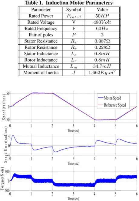
The membership functions before training and after training are shown in figure (5) and figure (6) respectively. To assess the pro-posed scheme, various simulation tests are carried out with PI controller and proposed scheme with ANFIS controller. The mo-tor parameters are in Table1
Fig. 4. Simulink model
Fig. 5. Membership functions generated before training
Fig. 6. Membership functions generated after training
ripple in torque at the time of speed change.
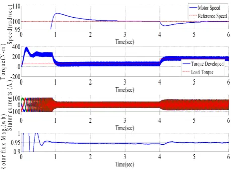
Figure (9 and 10) shows the load disturbance rejection capabili-ties of both the controllers, when the the load torque is suddenly changed from 25 Nm to 150 Nm. There is a considerable speed over shoot and speed dip(when the load torque rises) with PI controller as compared to proposed ANFIS scheme. The rotor flux level hardly changes in both the cases.
Table 1. Induction Motor Parameters Parameter Symbol Value Rated Power Pratrd 50HP
Rated Voltage V 480V olt
Rated Frequency F 60Hz
Pair of poles P 2
Stator Resistance Rs 0.087Ω
Rotor Resistance Rr 0.228Ω
Stator Inductance Ls 0.8mH
Rotor Inductance Lr 0.8mH
Mutual Inductance Lm 34.7mH
Moment of Inertia J 1.662Kg.m2
[image:4.595.319.548.466.642.2]Fig. 7. Trapezoidal speed tracking with PI controller
Fig. 8. Trapezoidal speed tracking with ANFIS controller
[image:4.595.56.282.478.665.2]Fig. 9. Transient performance under step load with PI controller
[image:5.595.57.287.297.474.2]Fig. 10. Transient performance under step load with ANFIS controller
Fig. 11. Transient performance under step speed and step load with PI controller
6. CONCLUSION
This paper presents a comparative performance study of indirect vector control drive with PI controller and the proposed scheme consisting of neural estimator and ANFIS controller. Simulation results shows that the proposed scheme is more robust during the load changes and eliminates the transients during sudden
Fig. 12. Transient performance under step speed and step load with ANFIS controller
changes in speed. Overall simulation result shows that the proposed scheme with ANFIS controller has better performance over PI controller.
In ANFIS controller,only few rules have been utilized in the rule base to provide the control actions instead of full combination of of all possible rules.Therefore it is proposed for future work that the real coded Genetic Algorithm (GA) can be utilized to train the ANFIS controller instead of the hybrid learning methods that were used in ANFIS controller. Again GA can be used to find the optimal settings for the input and output scaling factors for this controller instead of the widely used trial and error method.
7. REFERENCES
[1] M.V. Aware, A.G. Kothari, and S.O. Choube. Application of adaptive neuro-fuzzy controller (anfis) for voltage source inverter fed induction motor drive. InProc. of IPEMC Conf, volume 2, page 935939, 15-18 Aug,2000.
[2] B. K. Bose. Modern Power Electronics and AC Drives. Prentice-Hill PTR Companies, Inc. Upper Saddle River, NJ 07458, 2002.
[3] Ben Brahim, S. Tadakuma L., and A. Akdag. Speed control of induction motor without rotational transducer. IEEE Transaction on Industry Applications, 35(4):844– 850, July/August 1989.
[4] P. P. Cruz, J. M. Aquino, and M. R. Elizondo. Vector con-trol using anfis concon-troller with space vector modulation [ induction motor drive application ]. In Proc. of UPEC Conf., volume 2, page 545549, 6-8 Sept. 2004.
[5] J.S.R. Jang, C.T. Sun, and E. Mizutani.Neuro-Fuzzy and soft computing- A computational approach to learning and machine intelligence. PHI Pvt. Ltd. , New Delhi, 2006. [6] B. Karanayil, M. F. Rahman, and C. Grantham. Pi and
fuzzy estimators for on-line tracking of rotor resistance of indirect vector controlled induction motor drive. InProc. of IEEE International Conf., pages 820–825, 2001.
[7] S.H. Kim, S. Park, and J.Y. Yoo. Speed sensor less vec-tor control of induction movec-tor using neural networks.IEEE Transaction on Industrial Electronics, 48(3):609–614, June 2001.
[8] R. Krishnan.Electric motor drives modeling, analysis and control. PHI Pvt. Ltd, New Delhi, 2003.
[9] Chuen Chien Lee.Fuzzy Logic in Control Systems :Fuzzy Logic controller Part 1. IEEE, New Delhi, 1990.
[image:5.595.56.286.502.678.2][11] L.Zhen and L.Xu. Fuzzy learning enhanced speed con-trol of an indirected field-oriented induction machine drives.IEEE Transaction on Control System Technology, 8(2):270–278, March 2000.
[12] N. Mariun, S.B.M. Noor, J. Jasni, and O. S. Bennanes. A fuzzy logic based controller for an indirect vector con-trolled three phase induction motor. InProc. of IEEE Inter-national Conf., pages 1–4, 2004.
[13] M. Masiala, B. Vafakhah, A. Knight, and J. Salmon. Perfor-mances of pi and fuzzy-logic speed control of field oriented induction machine drives. InProc. of IEEE International Conf., pages 397–400, 2007.
[14] M. Mohamadian, E. Nowicki, F. Ashafzadeh, A. Chu, R. Sachdeva, and E. Evanik. A novel neural network troller and its efficient dsp implementation for vector con-trolled induction motor drives.IEEE Transaction on Indus-try Applications, 39(6):1622–1629, November/December 2003.
[15] M. N. Uddin, T. S. Radwan, and M. A. Rahman. Perfor-mances of fuzzy-logic-based indirect vector control for in-duction motor drive.IEEE Transaction on Industry Appli-cations, 38(5):1219–1225, Sept./Oct 2002.