http://dx.doi.org/10.4236/sgre.2014.54008
Application of Electrochemical
Supercapacitor to Photovoltaic System
on Unmanned Flying Machine
Shun-Ching Lee, Yusuf Dewantoro Herlambang
Department of Mechanical Engineering, National Kaohsiung University of Applied Sciences, Kaohsiung, Taiwan Email: [email protected]
Received 20 February 2014; revised 20 March 2014; accepted 27 March 2014
Copyright © 2014 by authors and Scientific Research Publishing Inc.
This work is licensed under the Creative Commons Attribution International License (CC BY). http://creativecommons.org/licenses/by/4.0/
Abstract
This paper presents an analysis of the characteristics of the photovoltaic supercapacitor system that moving fixedly along the longitude. A lot of equations concerning the characteristics are con-sidered including supercapacitor, direct motor, solar radiation from the sun to the photovoltaic module through the atmosphere. Runge-Kutta method is used to predict the time integrations, and Newton-Raphson method ensures the simultaneous solutions at each substeps. The machine flying takes one day trip or one year trip from different latitudes and different seasons. Around solar noon, the photovoltaic generator drives the direct current motor and charges the electrochemical supercapacitor simultaneously. An electrochemical supercapacitor battery is used as a secondary battery. The working ranges of electrochemical supercapacitor battery and direct current motor are found by the simultaneous solution of their characteristics. The thermostat system induces the excess currents and supplies heat energy to keep the photovoltaic module supercapacitor not be-low the ice point. This study shows the considerable benefits of the supercapacitor used for energy storage, and also finds a performance in which the presented photovoltaic supercapacitor system can continue working for about three and one half years on the trips from the equator and from the latitude of 30˚ and about four and one half years on the trip from the latitude of 60˚.
Keywords
Electrochemical Supercapacitor, Photovoltaic System, Photovoltaic Supercapacitor Module
1. Introduction
ECSC could bear a large number of cycles of charge-discharge without any reduction to its energy storage ca-pacity, and it is under normal operation if the charging voltage does not largely exceed the rated voltage of ECSC battery. In the recent years, the manufacturing technology for ECSC developed greatly, so the photovol-taic supercapacitor (PVSC) that combines PV module with ECSC has been considered. The ECSC may be mounted on the back of PV module and divided up into many ECSC cells. The number of ECSC cells on each module and the area of each ECSC cell can match the demand for driving electric machinery such as direct cur-rent (DC) motor.
The flying PVSC system includes the PVSC module, the DC motor, and the thermostat system. The PV ge-nerator supplies power to the DC motor for a flight plan during the day, and the energy stored in the ECSC cells makes the flight plan also possible at night, during sunrise, and during sunset. The voltage of the ECSC battery accompanying the output current can match the characteristic of DC motor by the disposition of ECSC cells in series and in parallel. The DC motor transforms electrical energy into mechanical energy for the task of flying all year around, and the separately excited motor is used because it works more approaching to the maximum
power point than the series motor at the given levels of radiation [1]. At any given operation voltage, the
dis-charge current from ECSC battery must be always larger than the driving current for DC motor so the working ranges of ECSC battery and DC motor must be found by the characteristics of them. The resistance of resistor is variable at any time to balance the currents in PVSC system, and the heat energy output of the resistive load is supplied to the thermostat system. The thermostat system is under operation for keeping the temperature of PVSC modules at zero degrees of Centigrade, while the surrounding temperature is below the ice point. The PV generator supplies power for the flying machine according to the voltage driving electric machinery, the level of radiation on PVSC module, and the temperature of PVSC module. The voltage driving electric machinery is de-fined as the operation voltage because all devices in PVSC system are wired in parallel. Neglecting the reflected radiation from the earth, the solar radiation incident on the surface of flying modules embraces the beam radia-tion and the diffuse radiaradia-tion. Different from the flight plans along fixed latitude, the PVSC modules for the flight plans along fixed longitude will meet different surrounding temperatures, in addition to different
atmos-pheric transmittances for beam and diffuse radiation [2] [3]. In the current study, the effect of air mass on
changes in the spectral distribution [4] is considered. Two transmittance-absorptance (TA) products from beam
and diffuse radiations are evaluated for the module with one glass cover, according to the laws of Snell, Fresnels, and Bougher. Accordingly, the effective level of radiation absorbed on the module surface is determined by the
HDKR model which is an integrated anisotropic model [5]-[7]. If the surrounding temperature is larger than the
ice point, the temperature of PVSC module is nearly equal to the surrounding temperature at any time because of high velocity flying.
2. ECSC Battery and DC Motor
The ECSC which has the constant capacitance of 5000, the current density of 0.1, the maximum and the mini-mum charge voltages of 2.70 and 1.70, and the maximini-mum and the minimini-mum discharge voltages of 2.54 and 1.62 is considered under safe conditions. Combining the characteristics of charge with discharge, ECSC can supply the range of voltage between 2.54 (the maximum discharge voltage) and 1.70 (the minimum charge voltage). Note that the two extremes accompany zero currents. The original ECSC mounted on PV module has the same
area of 0.633 m2. If it is divided into a lot of ECSC cells, each ECSC cell will have the same characteristics as
the original ECSC. But before being divided, the characteristics of the driven electric machinery must be
indi-cated. The present DC motor used on the flying machine has the relationship between current and voltage [1] [8]
According to the characteristics of ECSC [9]-[11], the charge and discharge characteristics for the present ECSC
battery have been shown by the author [12]. The simultaneous solutions of characteristics of both ECSC battery
and DC motor are 83.64 Vand −5.106 A [12].
3. One Day Trip and One Year Trip
If a flying machine at the altitude of A moves south or north along a fixed longitude and with the velocity of vy,
the difference of the latitude it passes per hour is
(
)
180 π
y e
v
R A
φ ∆ =
where Re is the radius of the earth and equal to 6372.797 km, and vy is positive when it flies north and nega-tive when it flies south. The flying machine starting from the equator and moving north will take a U-turn at the
latitude of 60˚, 12 h later, and come back 24 h later. Similarly, the flying machine starting from the latitude of
60˚ and moving south will take a U-turn at the equator 12 h later and come back 24 h later. If it flies north from
the latitude of 30˚, it will appear at the latitude of 60˚, 6 h later, at the latitude of 30˚, 12 h later, at the equator 18
h later, and come back 24 h later. But it will appear at the equator 6 h later and at the latitude of 60˚, 18 h later, if
it flies south from the latitude of 30˚. Accordingly, for a one day trip passing through 120˚ of the circle around
the earth, the flying speed should be
(
)
π36
e y
R A
v = + (2)
The PVSC system will present different behaviors, if it flies on different dates or takes one year trip from dif-ferent dates. In the analyses for one year trip, there is no difference in computational method between each day except for initial state of charge in ECSC cells because the flying machine always comes back 24 h later.
4. Solar Radiation
The solar radiation incident on a horizontal plane outside of the atmosphere is given by [8]
(
2 3 4 5)
1367 1.000110 3.4221 10 cos 1.280 10 sin 7.19 10 cos 2 7.7 10 sin 2 cos
o z
G = + × − B+ × − B+ × − B+ × − B θ (3)
where the solar constant is 1367 W/m2, the zenith angle θz is just the incidence angle of beam radiation on
the horizontal surface, and the variation of radiation flux energy is presented by indicating the variation of
earth-sun distance on the nth day of the year:
(
)
360 1365
B= n− (4)
The extraterrestrial radiation passes through the atmosphere and contributes beam and diffuse radiations to the
surfaces of PVSC modules. The transmittances for beam radiation τb at the altitude of 2.5 km through the
standard atmosphere with 23 km visibility for four climate types are given by [2]
2
0 1
0.2711 0.32313 0.6007 exp
cos
b
z
r
r r
τ
θ
= + −
(5)
where the correction factors r0, r1, and r2 at the equator and at the latitudes of 30˚ and 60˚ has been shown
by the author [12]. The diffuse transmittance for clear day, τd, can be predicted by the empirical relationship [3]
between the transmission coefficients for beam and diffuse radiation:
0.271 0.294
d b
τ = − τ (6)
Thus, the beam radiation Gb is equal to Go bτ , the diffuse radiation Gd is equal to Go dτ , and the total
radiation for clear sky on the horizontal surface is obtained by
(
0.271 0.706)
o b
G=G +
τ
(7)5. PV Generator
Beam radiation and anisotropic diffuse radiation are two components incident on the surfaces of moving PVSC modules. During the day, the cosine of the incidence angle of beam radiation on the horizontal surface at latitude
φ is given by
cosθ =sin sinδ φ+cos cos cosδ φ ω (8)
where
ω
is the hour angle, and δ is the declination of the sun at solar noon and found from an accurateequ-ation [13]:
(
)
36.918 399.912 cosB 70.257 sinB 6.758 cos 2B 0.907 sin 2B 2.679 cos 3B 1.48sin 3B 10
δ
= − + − + − + × −(9)
beam radiation
( )
τα
b and for diffuse radiation( )
τα
d passing through the PVSC module with one glass cover are found by Snell’s, Fresnel’s, and Bougher’s laws:( )
cos 2(
(
)
)
2(
(
)
)
2 2
sin tan
1
e 1
2 sin tan
r r r
KL bord
r r
θ θ θ θ θ
τα
θ θ θ θ
− − −
= − +
+ +
(10)
where θ and θr are the incidence and refraction angles, K is the glazing extinction coefficient, and L is
the glazing thickness. The air mass modifier predicting the change in the spectral distribution can be calculated by the empirical relation [4] [15]:
1 2 2 3 3 4 4
0.935823 0.54289 10 m 0.8677 10 m 0.527 10 m 0.11 10 m
air
M = + × − − × − + × − − × − (11)
Considering the effect of the earth’s curvature, the original air mass, m=1 cosθz , is modified into [16]
(
)
1.6341
cos z 0.5057 96.080 z
m
θ θ −
=
+ − (12)
At the reference conditions, the air mass is 1.5 which induces the incidence angle of 48.2˚ by Equation (12)
and Mair ref, of unity by Equation (11); moreover, Sref =Mair ref, , ref
( )
949 W/m2n
G
τα
= , because( )
0.949n
τα
= for normal incidence and Gref =1000 W/m2. Based on the HDKR model, the effectiveradia-tion absorbed on the module surface S is given by
(
)( )
(
)( )
{
1}
air b d b b d b d
S =M G +Gτ τα +G −τ τα (13)
According to the equivalent circuit, the electric characteristic of PV module is presented by the relationship between current and voltage:
mod mod mod mod
mod exp 1
s s
L o
sh
V I R V I R
I I I
a R
+ +
= − − −
(14)
The five parameters in the model are determined by the effective absorbed solar ratio Sratio =S Sref and the
module temperature Tmod [8].
6. PVSC System
Some characteristics of the components in PVSC system are presented in [12]. At the initial state, the ECSC
batteries all are at full state of charge except one secondary battery which is at the lowest fractional state, 1
. 0
=
F . One of the primary batteries drives the DC motor while the sun is under the horizon, and it also
sup-plies energy to the DC motor while the PV generator does not produce enough during sunrise and during sunset. The PV generator has chance to charge the battery around solar noon, in addition to driving the DC motor. If the PV generator is formed by five PV modules in series and five PV modules in parallel as shown in (12), the pri-mary battery has a chance of being recharged to full state, and then PV generator can charge the secondary bat-tery. While the PV generator does not produce enough during sunset, the secondary battery discharges instead of primary battery. The resistive load of the variable resistor will induce the excess currents from ECSC battery and PV generator, and supply heat energy to the heater controlled by the thermostat. The simultaneous solutions of the characteristics of the four components are found according to the conditions:
, mod and , mod
p PV ECSC motor load s PV ECSC motor load load
N I =I +I +I N V =V =V =I R (15)
When the PVSC modules are under insolation, they supply the system with the voltage of Ns PV, Vmod and the
current of Np PV, Imod by Ns PV, modules in series and Np PV. modules in parallel, and Ns PV, =5 and
. 5
p PV
N = in the current study. But once the PVSC modules are not under insulation and disconnected from the
system, the battery bears alone driving the DC motor:
and
ECSC motor load ECSC motor load load
I I I V V I R
− = + = = × (16)
out per 5 minutes.
7. Characteristic Analysis
7.1. One Day Trip
The PVSC modules all are fixed horizontally on the flying machine. One day trips along fixed longitude from
the latitudes of 0˚, 30˚, and 60˚ are considered. As shown in [12], the surrounding temperatures at the altitude of
2.5 km are determined by the Lapse rate of −9.8 C/kmo , and the transmittance correction factors on three
clear days, summer solstice (SS), autumn equinox (AE), and winter solstice (WS) are also shown [2]. According
to Equation (1), the flying machine moving along fixed longitude with the velocity of 556.35 km/hr will come
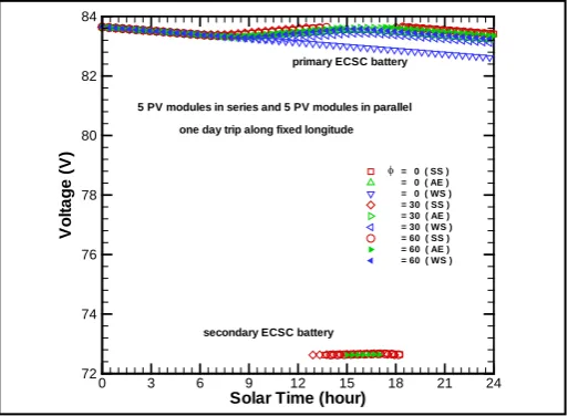
back 24 h later. The surrounding temperature at different latitude is evaluated by the interpolation of a Lagrange polynomial. Because of high speed moving, the energy absorbed by the mass of PVSC module will completely dissipate, and the temperature of PVSC module tends to the surrounding temperature at any point of the time. The thermostat keeps the PV modules at ice point if the surrounding temperatures are less than zero degrees of Centigrade. The components of the PVSC system all are wired in parallel and the profiles of the operation
vol-tage are presented in Figure 1. On any one day trip, the primary battery with full charge starts to drive the DC
motor at midnight by the voltage of 83.64 V accompanying the discharge current of −5.106 A. The primary
battery dominates the PVSC system by the voltage between 72.62 V and 83.64 V. When the primary battery is recharged to the full state, the secondary battery with the fractional state of 0.1 is charged by the voltage of 72.62 V.
The secondary battery dominates the PVSC system at about 72.65 V, and a larger initial charge of secondary battery must be chosen if a larger voltage is requested. For apparent presenting the difference, the fractional state of 0.1 is chosen in the current study. The secondary battery can save the energy and will discharge while the PV generator does not produce enough during sunset. The secondary battery prolongs rest time of primary battery. After one day trip, the battery moving from the equator on the day of WS has the lowest state of charge,
0.9153
F= , and moving from the equator on the day of SS has the largest state of charge, F=0.9810. The
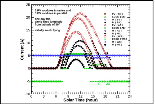
profiles of the currents are shown in Figure 2, Figure 3, Figure 4, Figure 5 for four components: PV generator
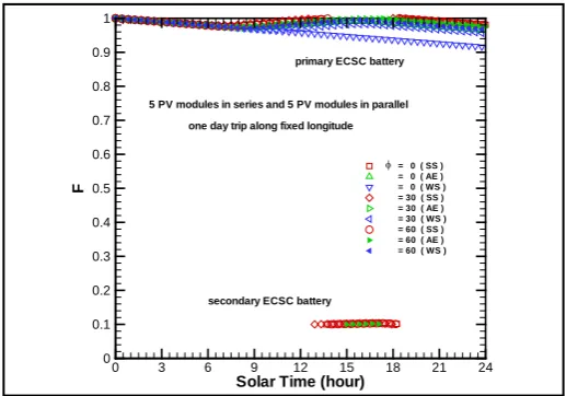
(PV), ECSC battery (ECSC), DC motor (M), and resistive load (R). The profiles of the fractional state of charge
are shown in Figure 6.
The PV generator moving from the equator on the day of SS supplies energy from 5:10 at the latitude of
25.83˚, but does not produce enough until 6:35. The resistance induces the excess current from battery before
[image:5.595.185.442.504.692.2]5:15, and induces the excess currents from both battery and PV generator from 5:15 to 6:35. From 6:35 to 7:40, the battery is at rest and the resistance induces the excess current from PV generator which drives alone the DC motor. At 7:40, the PV generator can drive the DC motor and recharge the battery simultaneously. From 9:20 to
Figure 1. Operational voltage in PVSC system on one day trip from different latitudes and on different days.
Solar Time (hour)
V
o
lt
a
g
e
(V
)
0 3 6 9 12 15 18 21 24
72 74 76 78 80 82 84
= 0 ( SS ) = 0 ( AE ) = 0 ( WS ) = 30 ( SS ) = 30 ( AE ) = 30 ( WS ) = 60 ( SS ) = 60 ( AE ) = 60 ( WS )
5 PV modules in series and 5 PV modules in parallel one day trip along fixed longitude
φ
primary ECSC battery
Figure 2. Current profiles in PVSC system for PV generator (PV), ECSC battery (ECSC) with charging and discharging, DC motor (M), and resistive load (R) on one day trip from the equator.
Figure 3. Current profiles in PVSC system on one day trip initially north flying from the latitude of 30˚.
Figure 4. Current profiles in PVSC system on one day trip initially south flying from the latitude of 30˚.
Solar Time (hour)
C u rr e n t (A )
0 3 6 9 12 15 18 21 24
-10 -5 0 5 10 15 20 25
PV ( SS ) ECSC ( SS ) M ( SS ) R ( SS ) PV ( AE ) ECSC ( AE ) M ( AE ) R ( AE ) PV ( WS ) ECSC ( WS ) M ( WS ) R ( WS )
5 PV modules in series and 5 PV modules in parallel one day trip along fixed longitude from the equator
Solar Time (hour)
C u rr e n t (A )
0 3 6 9 12 15 18 21 24
-10 -5 0 5 10 15 20 25
PV ( SS ) ECSC ( SS ) M ( SS ) R ( SS ) PV ( AE ) ECSC ( AE ) M ( AE ) R ( AE ) PV ( WS ) ECSC ( WS ) M ( WS ) R ( WS )
5 PV modules in series and 5 PV modules in parallel one day trip along fixed longitude from latitude of 30 initially north flying
o
Solar Time (hour)
C u rr e n t (A )
0 3 6 9 12 15 18 21 24
-10 -5 0 5 10 15 20 25
PV ( SS ) ECSC ( SS ) M ( SS ) R ( SS ) PV ( AE ) ECSC ( AE ) M ( AE ) R ( AE ) PV ( WS ) ECSC ( WS ) M ( WS ) R ( WS )
5 PV modules in series and 5 PV modules in parallel one day trip along fixed longitude from latitude of 30 initially south flying
[image:6.595.184.444.82.263.2] [image:6.595.185.443.307.480.2] [image:6.595.184.444.516.693.2]Figure 5. Current profiles in PVSC system on one day trip from lati-tude of 30˚.
Figure 6. Profiles of fractional state of charge in primary and second-ary batteries on one day trip from different latitudes and on different days.
13:40, the current through the resistance is larger than the charge current. At 11:55, the photocurrent and resis-tance current simultaneously present the local minimums of the profiles. At 13:40, the primary battery has
reached to the full state of charge and the secondary battery with F =0.1 starts to charge. At the same time, the
resistance current is the maximum of the profile which is near 3 times of the motor current. From 13:40 to 18:30, the motor current decreases to 4.23 A and the battery charges at about 1.47 A. The resistance current is less than the motor current again at 16:35. From 17:25 to 17:40, the secondary battery is also at rest. The resistance
cur-rent is larger than the motor curcur-rent again from 17:40 to 18:00. The secondary battery discharges at −6.17 A
from 17:40 to 18:35, and comes back toF= 0.1 at 18:35. Thereafter, the primary battery works again till
mid-night ending with F = 0.9810, and bears alone driving the DC motor after sunset at 18:50 and at the latitude of
25.83˚. The heat energy output of the resistive load totals 21.15MJ.
The PV generator moving from the equator on the day of AE supplies energy from 6:00 at the latitude of 30˚,
and produces enough at 7:35. From 7:35 to 9:25, the battery is at rest. From 9:25 to 11:35, the PV generator can drive the DC motor and recharge the battery simultaneously. From 11:35 to 12:20, the battery is at rest again. From 12:20 to 14:50, the PV generator also can drive the DC motor and recharge the battery simultaneously. From 9:25 to 11:35 and 12:20 to 14:45, the excess current induced by the resistance is small. The resistance cur-rent is larger than the motor curcur-rent with the small amounts from 9:05 to 9:20, 11:35 to 11:50, 12:00 to 12:15,
Solar Time (hour)
C
u
rr
e
n
t
(A
)
0 3 6 9 12 15 18 21 24
-10 -5 0 5 10 15 20 25
PV ( SS ) ECSC ( SS ) M ( SS ) R ( SS ) PV ( AE ) ECSC ( AE ) M ( AE ) R ( AE ) PV ( WS ) ECSC ( WS ) M ( WS ) R ( WS )
5 PV modules in series and 5 PV modules in parallel one day trip along fixed longitude from latitude of 60o
Solar Time (hour)
F
0 3 6 9 12 15 18 21 24
0 0.1 0.2 0.3 0.4 0.5 0.6 0.7 0.8 0.9 1
= 0 ( SS ) = 0 ( AE ) = 0 ( WS ) = 30 ( SS ) = 30 ( AE ) = 30 ( WS ) = 60 ( SS ) = 60 ( AE ) = 60 ( WS )
5 PV modules in series and 5 PV modules in parallel one day trip along fixed longitude
φ
primary ECSC battery
[image:7.595.183.442.300.481.2]and 14:50 to 15:00. At 11:55, the photocurrent and the resistance current simultaneously have the local mini-mums of the profiles. From 14:50 to 16:30, the battery is at rest the third time.
Thereafter, the battery works again till midnight ending with F = 0.9638, and works alone after sunset at
18:00 and at the latitude of 30˚. The primary battery can’t reach to the full state of charge, and the secondary
battery is always at rest. The heat energy output of the resistive load totals 7.77 MJ.
The PV generator moving from the equator on the day of WS supplies energy from 7:15 to 16:45. The flying
machine meets the sunrise and the sunset at the latitude of 36.25˚. The PV generator does not produce enough all
day long. The photocurrent is nearly equal to the resistance current during the day, and they have the minimum at 11:55. The battery discharges the whole day, and the final state of charge is 0.9153. The heat energy output of the resistive load totals 5.56 MJ.
The PVSC system has two initial directions, flying north and flying south, if it moves from the latitude of 30˚.
The results for initial south flying are presented in brackets following the results for initial north flying. The PV
generator moving from the latitude of 30˚ on the day of SS supplies energy from 3:55 (6:00) at the latitude of
49.58˚ (0.0˚), but does not produce enough until 5:50 (7:15). From 5:50 (7:15) to 7:35 (8:10), the primary
bat-tery is at rest. From 7:35 (8:10) to 12:55 (14:50), PV generator recharges the primary batbat-tery until it is at full state, in addition to driving the DC motor. From 9:05 (9:10) to 16:00 (16:40), the resistance current is larger than the motor current. From 11:10 (11:00) to 12:50 (12:45), the resistance current is over two times of motor current.
The maximum of the profile of photocurrent is presented at 12:05 (11:50). The secondary battery withF= 0.1
begins charging at 12:55 (14:50). From 12:55 (14:50) to 16:40 (19:15), the motor current decreases to 4.23A
and the battery charge is at about 1.47 A. The maximum of the resistance current is presented at 12:55 (11:50). From 12:55 to 14:10, the resistance current is over three times of motor current, but there is not such large cur-rent for the initial south flying. The resistance curcur-rent is again over two times of motor curcur-rent from 14:10 (14:50) to 15:15 (15:25). From 16:45 (18:05) to 17:00 (18:30), the secondary battery is also at rest. From 17:00 (18:30) to 17:15 (19:00), the resistance current is also larger than the motor current. The secondary battery
dis-charges at −6.17 A from 17:00 (18:30) to 17:55 (19:15), and comes back to F = 0.1 at 17:55 (19.15). Thereafter,
the primary battery works till midnight ending with F = 0.9789 (0.9836), and bears alone driving the DC motor
after sunset at 18:00 (20:05) and at the latitude of 0.0˚ (49.58˚). The heat energy output of the resistive load
to-tals 25.05 MJ (23.38 MJ).
The PV generator moving from the latitude of 30˚ on the day of AE supplies energy from 6:00 (6:00) at the
latitude of 60.0˚ (0.0˚), and produces enough at 7:55 (7:15). From 7:55 (7:15) to 9:10 (8:15), the primary battery
is at rest. The resistance current is larger than the motor current from 9:00 (16:20) to 9:05 (16:35) and from 10:25 (9:20) to 14:40 (13:30). The maximum resistance current and the maximum photocurrent are presented simultaneously at 12:35 (11:25). From 9:10 (8:15) to 15:50 (16:00), the PV generator can drive the DC motor and recharge the battery simultaneously. From 15:50 (16:00) to 16:50 (16:20), the primary battery is at rest again.
Thereafter, the primary battery discharges till midnight ending with F = 0.9728 (0.9743), and bears alone driving
the DC motor after sunset at 18:00 (18:00) and at the latitude of 0.0˚ (60.0˚). The heat energy output of the
resis-tive load totals 15.40 MJ (14.96 MJ).
The PV generator moving from the latitude of 30˚ on the day of WS supplies energy from 8:05 (6:00) at the
latitude of 49.58˚ (0˚), and produces enough at 9:40 (7:35). From 9:40 (7:35) to 11:00 (8:55), the primary battery
is at rest. From 11:00 (8:55) to 15:15 (13:00), the PV generator can drive the DC motor and charge the primary battery simultaneously. The resistance current is larger than the motor current from 10:50 (8:45) to 10:55 (8:50). At 13:05 (10:55), the photocurrent reaches to the maximum and the resistance current presents the local maxi-mum. From 15:15 (13:00) to 16:35 (14:20), the primary battery is at rest again. Thereafter, the primary battery
discharges till midnight ending with F = 0.9564 (0.9551), and bears alone driving the DC motor after sunset at
18:00 (15:55) and at the latitude of 0.0˚ (49.58˚). The heat energy output of the resistive load totals 7.18 MJ
(7.30 MJ).
The PV generator moving from the latitude of 60˚ on the day of SS supplies energy from 4:45 at the latitude
of 36.25˚, and produces enough at 6:40. From 6:40 to 7:55, the primary battery is at rest. From 7:55 to 17:10, the
at about 1.47 A from 14:00 to 17:15. From 17:15 to 17:40, all batteries are at rest and PV generator alone drives
the DC motor. From 17:40 to 18:25, the secondary battery discharge at −6.17 A. Thereafter, the primary battery
works till midnight ending with F = 0.9804, and bears alone driving the DC motor after sunset at 19:15 and at
the latitude of 36.25˚. The heat energy output of the resistive load totals 22.22 MJ.
The PV generator moving from the latitude of 60˚ on the day of AE supplies energy from 6:00 at the latitude
of 30.0˚, and produces enough at 7:20. From 7:20 to 8:20, the primary battery is at rest. From 8:20 to 16:35, the
PV generator can drive the DC motor and charge the primary battery simultaneously. The resistance current is larger than the motor current from 9:15 to 14:40, and over 2 times of the motor current from 10:50 to 13:10. At 12:05, the photocurrent and the resistance current have the maximums respectively. From 15:00 to 16:35, the primary battery is at full state and the secondary battery is at the state of being charged. The motor current is de-creasing to 4.23 A from 15:00 to 17:15, and the secondary battery charges at about 1.46 A from 15:00 to 16:35. The secondary battery is at rest for 15 minutes from 16:35. Thereafter, the primary battery works till midnight
ending with F = 0.9766, and bears alone driving the DC motor after sunset at 18:00 and at the latitude of 30.0˚.
The heat energy output of the resistive load totals 20.80 MJ.
The PV generator moving from the latitude of 60˚ on the day of WS supplies energy from 6:50 at the latitude
of 25.83˚, and produces enough at 8:05. From 8:05 to 9:00, the primary battery is at rest. From 8:50 to 8:55,
from 10:00 to 14:00, and at 15:05 the resistance current is larger than the motor current. At 11:5, the photocur-rent and the resistance curphotocur-rent have the maximums respectively. From 9:00 to 15:00, the PV generator can drive the DC motor and recharge the primary battery simultaneously. From 15:05 to 16:00, the primary battery is at
rest again. Thereafter, the primary battery works till midnight with F = 0.9670, and bears alone driving the DC
motor after sunset at 17:10 and at the latitude of 25.83˚. The heat energy output of the resistive load totals 15.11
MJ.
7.2. One Year Trip
Based on the analytical methods for one day trips, one year trips start from spring equinox (SE), summer solstice, autumn equinox, and winter solstice to next year are considered. The profiles of the surrounding temperatures at
the equator and the latitudes of 30˚ and 60˚ for the whole year are determined by the interpolation of two
La-grange quadratic equations, one for dates before SS and one for dates after SS. The two quadratic equations are determined by the following method. The average surrounding temperature on the first day of the year is equal to that on the last day. The surrounding temperature on the last day of the year is determined by the condition that the value on the day of WS derived from the interpolation is just equal to the value on the day of WS
pre-sented in [12]. Thus, the surrounding temperatures on any day can be found. Note that the transmittance
correc-tion factors at the latitudes of 0˚ and 60˚ are fixed all year round, but they are different for four seasons at the
la-titudes of 30˚.
Moreover, the schematic presentations to the profiles for 12 cases, flying from three latitudes and from four
dates, are shown in Figure 7. Each sharp decrease indicates that the primary battery is at lowest state of charge
and another primary battery with full charge is used. The time changing primary battery is always at night, at 20:10 on the 234th day of the trip from the equator and from the day of SE for example. Including the conditions
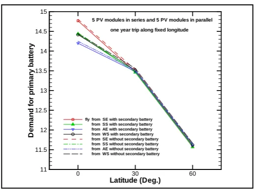
with and without secondary battery, the demands for the primary battery in 24 cases are shown in Figure 8, and
the results are presented by the summation of the number of used up primary battery and the discharge fraction
of the using battery, 1−F. The values for the system with secondary battery are always less than those without
secondary battery, but the systems with and without secondary battery have the same consumptions of the
pri-mary battery. According to the demands for the pripri-mary battery presented in Figure 8, the ECSC batteries can
work for about three and one half years on the trips from the equator and from the latitude of 30˚ and about one
half and four years on the trip from the latitude of 60˚.
8. Conclusions
Figure 7. Schematic presentation about profiles of heat energy output of resistive load on one year trip from four seasons and from three lati-tudes.
Figure 8. Demands for ECSC battery on one year trip from four sea-sons, from three latitudes, and with or without secondary battery.
maximum voltage of working range for ensuring that the current from DCSC battery is always larger than the current to DC motor. At the actual maximum voltage the fractional state of charge is 1.0, and furthermore the actual minimum of working range is the voltage at which the fractional state of charge is 0.1 because the mini-mum charge voltage of the possible working range accompanies zero charge current. The PVSC system has 50 ECSC batteries mounted on 25 PV modules, and 49 ECSC batteries with full state of charge are primary battery and one ECSC battery with the lowest fractional state of charge is secondary battery.
The flying machine usually takes the routes combining the paths along fixed latitudes and along fixed longi-tudes. The characteristics of PVSC system flying along fixed longitude were found in this work. Newton method and Runge-Kutta method complete the time integration per 5 min. The detail results for 1 day trips from three latitudes and on the days of SS, AE, and WS are presented for the design engineers. The flight plans considered total 24 cases for 1 year trips. The demands for primary battery are the same for the flight plans from the
lati-tudes of 30˚ and 60˚ and from any seasons. The 49 ECSC batteries with full charge can work for about three and
one half years on the trips from the equator and from the latitude of 30˚ and about one half and four years on the
trip from the latitude of 60˚.
nth day of the year
H
e
a
t
e
n
e
rg
y
(M
J
)
0 60 120 180 240 300 360
0 5 10 15 20 25 30 35 40
5 PV modules in series and 5 PV modules in parallel one year trip along fixed longitude symbols for the trip from the equator and from the day of SE
Latitude (Deg.)
D
e
m
a
n
d
fo
r
p
ri
m
a
ry
b
a
tt
e
ry
0 30 60
11 11.5 12 12.5 13 13.5 14 14.5 15
fly from SE with secondary battery from SS with secondary battery from AE with secondary battery from WS with secondary battery from SE without secondary battery from SS without secondary battery from AE without secondary battery from WS without secondary battery
[image:10.595.183.444.319.514.2]Acknowledgements
This research was supported by National Science Council at Taiwan, Contract No. NSC 100-2221-E-151-058.
References
[1] Townsend, T.U. (1989) A Method for Estimating the Long-Term Performance of Direct-Coupled Photovoltaic Systems. M.S. Thesis, University of Wisconsin-Madison, Madison.
[2] Hottel, H.C. (1976) A Simple Model for Estimating the Transmittance of Direct Solar Radiation Through Clear At-mospheres. Solar Energy, 18, 129-134. http://dx.doi.org/10.1016/0038-092X(76)90045-1
[3] Liu, B.Y.H. and Jordan, R.C. (1960) The Interrelationship and Characteristic Distribution of Direct, Diffuse and Total Solar Radiation. Solar Energy, 4, 1-19. http://dx.doi.org/10.1016/0038-092X(60)90062-1
[4] King, D.L., Boyson, W.E. and Kratochvil, J.E. (2004) Photovoltaic Array Performance Model. Sandia National Labor-atories Report SAND, 2004-3535.
[5] Hay, J.E. and Davies, J.A. (1980) Calculation of the Solar Radiation Incident on an Inclined Surface. Proceedings of
the 1st Canadian Solar Radiation Data Workshop, Toronto, Canada.
[6] Klucher, T.M. (1979) Evaluation of Models to Predict Insolation on Tilted Surfaces. Solar Energy, 23, 111-114.
http://dx.doi.org/10.1016/0038-092X(79)90110-5
[7] Reindl, D.T., Beckman, W.A. and Duffie, J.A. (1990) Evaluation of Hourly Tilted Surface Radiation Models. Solar
Energy, 45, 9-17. http://dx.doi.org/10.1016/0038-092X(90)90061-G
[8] Duffie, J.A. and Beckman, W.A. (2010) Solar Engineering of Thermal Processes. 3rd Edition, John Wiley and Sons Ltd., New York.
[9] Pang, S.C., Anderson, M.A. and Chapman, T.W. (2000) Novel Electrode Materials for Thin-Film Ultracapacitors: Comparison of Electrochemical Properties of Sol-Gel-Derived and Electrodeposited Manganese Dioxide. Journal of
the Electrochemical Society, 147, 444-450. http://dx.doi.org/10.1149/1.1393216
[10] Frackowiak, E. and Beguin, F. (2001) Carbon Materials for the Electrochemical Storage of Energy in Capacitors. Car-bon, 39, 937-950. http://dx.doi.org/10.1016/S0008-6223(00)00183-4
[11] Lufrano, F. and Staiti, P. (2010) Mesoporous Carbon Materials as Electrodes for Electrochemical Supercapacitors.
Journal of the Electrochemical Society, 5, 903-916.
[12] Lee, S.C. (2011) Characteristic Analysis of a Photovoltaic System Flying at Fixed Latitude. Energy Conversion and
Management, 52, 3337-3346. http://dx.doi.org/10.1016/j.enconman.2011.07.002
[13] Spencer, J.W. (1971) Fourier Series Representation of the Position of the Sun. Search, 2, 162-172.
[14] Brandemuehl, M.J. and Beckman, W.A. (1980) Transmission of Diffuse Radiation through CPC and Flat-Plate Col-lector Glazings. Solar Energy, 24, 511-513. http://dx.doi.org/10.1016/0038-092X(80)90320-5
[15] Fanney, A.H., Dougherty, B.P. and Davis, M.W. (2002) Evaluating Building Integrated Photovoltaic Performance Models. Proceedings of 29th IEEE Photovoltaic Specialists Conference (PVSC), New Orleans, 19-24 May 2002, 1642- 1645.