Performance Analysis of Soft-Switching Isolated
Buck-Boost Converters with Interleaved
Functioning Of Boost Converter Using
Mathlab/Simulink
Jaffer Hussiani Baig 1, Anguraja.R2, Dr.R.Prakash3
1
PG Scholar, Department of Electrical and Electronics Engineering, Don Boscov Institute of Technology, Bengaluru, Karnataka, India. )
2
Associate Professor, Department of Electrical and Electronics Engineering, Don Bosco Institute of Technology, Bengaluru, Karnataka, India)
3
Professor & Head of the Department of Electrical and Electronics Engineering, Don Bosco Institute of Technology, Bengaluru, Karnataka, India.)
Abstract: Due to the depletion of the fossil fuels day by day, this has enforced the mankind to rely abundantly on the renewable energy sources like solar energy, wind energy and fuel cells as well as the photo voltaic cells. But the open-circuit voltage of renewable sources, such as photovoltaic fuel-cell and thermoelectric generator is much higher than the maximum power point voltage; the highest conversion efficiency is usually achieved at the open-circuit voltage if an isolated boost converter is employed. In this case, high efficiency at the maximum power point, which is very important for the renewable power system, cannot be ensured. For the applications of battery charging and dis charging high conversion efficiency over the entire operating range is needed. Hence a new method has been described in this paper called isolated buck boost converter with single stage power conversion with interleaved functioning of the boost converter for improving the efficiency of the sources in terms of voltage and current. Hence, a transformer with reduced turns ratio and parasitic parameters, and low-voltage rated MOSFETs and diodes with better switching and conduction performances can be applied to improve the efficiency.
Keywords: Dc-Dc converter, interleaved boost converter, IBB converter, soft-switching.
I. INTR1ODUCTION
Therefore, an IBB converter can be derived easily by inserting a transformer into a non-isolated buck-boost converter, for example the Cuk, SEPIC, and ZETA converters. However, similar to the flyback converter, the isolated Cuk , ZETA, and SEPIC converters still suffer from the disadvantages of high component stress, hard-switching, and low efficiency.
Hence a new method has been described in this paper called isolated buck boost converter with single stage power conversion with interleaved functioning of the boost converter for improving the efficiency of the sources in terms of voltage and current. Hence, a transformer with reduced turns ratio and parasitic parameters, and low-voltage rated MOSFETs and diodes with better switching and conduction performances can be applied to improve the efficiency with the soft switching.
II. OPERATIONAL PRINCIPLES OF IBB CONVERTER
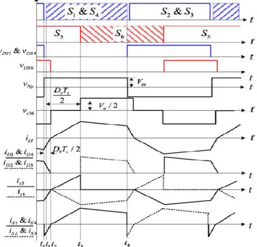
The IBB converter taken as an example to be analyzed is redrawn in Fig. 1. vDS1 ,vDS4 , and vDS6 are the drain to source
[image:3.612.181.432.264.398.2]voltages of S1 , S4 , and S6 , respectively. νNPand vS56 are the voltages of the primary side and secondary side of the transformer. And iLfis the current flowing through the inductor Lf .A proper dead-time is necessary for the primary-side switches to achieve ZVS and avoid shot-through of the switching bridges, but dead-time is not needed for the secondary-side switches S5and S6 . To simplify the analysis, the parasitic capacitance of the MOSFET is ignored.
Fig 1 IBB Converter
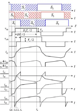
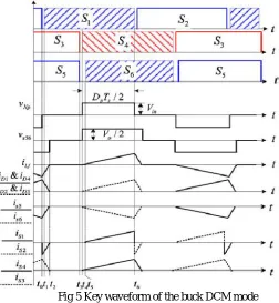
The converter can work either in the buck mode (G <1) or the boost mode (G ≥ 1). According to the waveform of the secondary-side current iLf, each operation mode can be further divided into continuous conduction mode (CCM) and discontinuous conduction mode (DCM). The soft switching waveforms of the boost and buck converter in the CCM mode as well as in the DCM mode are shown in the figures 2, figure 3 figure 4 and figure 5 respectively
[image:3.612.181.435.468.712.2]Fig 3 Key waveform of the boost DCM mode
[image:4.612.183.436.348.712.2]Fig 5 Key waveform of the buck DCM mode
III.DESIGN OF THE IBB SYSTEM
Based on the proposed bridgeless boost rectifiers, novel IBB converters can be derived by employing the input stage of an isolated buck converter as the primary-side circuit of the IBB converters. The primary-side circuit can be full-bridge, half bridge, or three-level half-bridge, Since the focus of this paper is the boost rectifiers, only the IBB converter topologies with full-bridge input stage are Obviously, the input stage of the IBB converter is a buck cell, the output stage is a bridgeless boost cell, and the two cells are linked by a high-frequency inductor and transformer. This structure is similar to the non-isolated two-switch buck-boost converter High conversion efficiency.
Fig 6 General architecture of IBB converter
[image:5.612.198.418.480.641.2]Fig 7 Conventional IBB circuit diagram
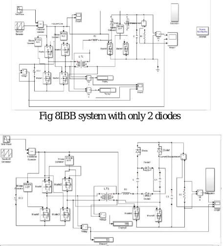
[image:6.612.212.440.264.516.2]The proposed IBB system with two diodes, with bridge rectifier circuit arrangement and with the increasing passive elements is shown in the figures 8, figure 9 and figure 10 respectively. This IBB system has better performance than the conventional type
Fig 8IBB system with only 2 diodes
[image:6.612.203.445.555.708.2]Fig 9 IBB system with diodes in full bridge arrangements
IV. RESULTS AND DISCUSSION
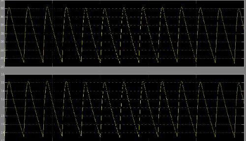
[image:7.612.179.433.144.258.2]In this section we will discuss simulation results of the components designed and the simulation results of a interleaved functioning of a boost converter using Math lab and Simulink software. The simulation0results of phase angle waveform, frequency waveform, output voltage and current waveforms of the IBB system of the Figures 8, 9 and 10are presented. The codingresults of 60V IBB converter system output is also shown below.
[image:7.612.178.434.287.401.2]Fig 11 voltage and current waveform of conventional IBB system
Fig 12 voltage and current waveform of 2 diode IBB system
Fig 13 voltage and current waveform of full bridge IBB system
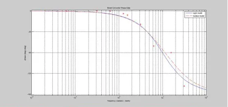
[image:7.612.181.434.431.544.2] [image:7.612.181.431.575.718.2]From the simulation results of the figure 12, 13 and 14 we can see that voltage is boosted in the secondary side and the switching losses are comparatively low in comparison with convention type IBB system and voltage boosting takes with 2 diodes, and diodes with full bridge arrangement and by increasing the passive element components. The frequency response and the phase angle response by writing the coding program in the Math lab with the values obtained from the proposed IBB system is shown below
[image:8.612.210.435.136.237.2] [image:8.612.208.441.268.377.2]Fig 15 Frequency response curve of proposed IBB system
Fig 16 Phase angle response curve of proposed IBB system
V.CONCLUSION
IBB converters with single-stage power conversion with interleaved functioning of boost rectifiers have been proposed and investigated in this paper. A full-bridge IBB converter with a voltage multiplier on the secondary-side bridgeless boost rectifier has been investigated. The voltage stresses of the semiconductors in the boost-rectifier are reduced significantly due to the voltage multiplier; hence, low-voltage-rated devices with better conduction and switching performance can be used to improve efficiency especially in the field of renewable energy source outputs. In other words, this converter is more attractive for high-output-voltage applications. Frequency and phase angle responses are drawn by coding with output values obtained from the voltage and current waveformswhich are designed in the Mathlab/Simulink.
REFERENCES
[1] G. Di Capua, S. A. Shirasavar, M. A. Hallworth, and N. Femia, “An enhanced model for small-signal analysis of the phase-shifted full-bridgeconverter,” IEEE Trans. Power Electron., vol. 30, no. 3, pp. 1567–1576, Mar. 2015.
[2] Z. Guo, D. Sha, and X. Liao, “Input-seriesoutput-parallel phase-shift full-bridge derived DCDC converters with auxiliary LC networks to achieve wide zero-voltage switching range,” IEEE Trans. Power Electron., vol. 29, no. 10, pp. 508– 513, Oct. 2014.
[3] H. Wu and Y. Xing, “Families of forward converters suitable for wideinput voltage range applications,” IEEE Trans.Power Electron., vol. 29, no. 11, pp. 6006–6017, Nov. 2014.
[4] Y. Wang, W. Liu, H. Ma, and L. Chen, “Resonance analysis and softswitching design of isolated boost converter with coupled inductors for vehicle inverter application,” IEEE Trans. Power Electron., vol. 30, no. 3, pp. 1383–1392, Mar. 2015.
[5] F. Evran and M. T. Aydemir, “Isolated high step-up DC-DC converterwith low voltage stress,” IEEE Trans. Power Electron., vol. 29, no. 7,pp.3591–3603, Jul. 2014.
[6] Y. Zhao, W. Li, Y. Deng, and X.He, “Analysis, design, and experimentation of an isolated ZVT boost converter with coupled inductors,” IEEETrans. Power Electron., vol. 26, no. 2, pp.541–550, Feb. 2011.
[7] H. Keyhani and H. A. Toliyat, “Partial-resonant buck-boost and flyback DC-DC converters,” IEEE Trans. Power Electron., vol. 29, no. 8, pp. 4357– 4365, Aug. 2014.
[8] C. Yao, X. Ruan, X. Wang, and C. K. Tse, “Isolated buck-boost DC/DC converters suitable for wide input-voltage range,” IEEE Trans. PowerElectron., v ol. , no. 9, pp. 2599–2613, Sep. 2011.
pp. 2817–2828, Jun. 2014
[11] M. Jang and V. G. Agelidis, “A boost-inverter-based, battery-supported fuel-cell sourced three-phase stand-alone power supply,” IEEE Trans.Power Electron., vol. 29, no. 12, pp. 6472–6480, Dec. 2014
[12] I. Laird and D. D.-C. Lu, “High step-up DC/DC topology and MPPT algorithm for use with a thermoelectric generator,” IEEE Trans. PowerElectron., vol. 28, no. 7, pp. 3147–3157, Jul. 2013
AUTHORS
A. Jafferhussianibaig- Received B.E in Electrical and Electronics Engineering from AIT, Chikmagaluru in the year 2014 and now currently pursuing M.Tech in Power System Engineering from DBIT, Bengaluru, His academic interest area include power generation, Renewable Energy Sources , power electronics and power systems. E-mail address: [email protected] B. Anguraja R – Received B.E in Electrical and Electronics Engineering from Bharathidasan University in the year 1996 and
M.Tech in High Voltage Engineering from SASTRA University in the year 2004.He is pursuing Ph.D. in High Voltage Engineering. He is currently working as Associate Professor in Departmentof electrical and electronics engineering in Don Bosco Institute of Technology. His research interests includes are Power System, power electronics, Renewable Energy and High Voltage Engineering.E-mail address:[email protected].