5
XI
November 2017
Design and Development of Fixture for Pillar
Drilling Machine
Nand Mangukia1, Nandish Mangukia2, Meet Rachhadia3, Ayanesh Joshi4
1,2,3
(Student), 4(Assistant Professor) Mechanical Engineering Department, A. D. Patel Institute of Technology, New V V Nagar, Gujarat, India.
Abstract : Fixture currently employed for drilling holes is very conventional and pristine. Problems occurring in current fixtures are: Fixture setup is done manually, due to this cycle time is more. Product quality is not obtained as per specification. • Labor fatigue increases. • More exasperating to operator to load and unload. This problem is needed to be solved to meet the current trends of designing and manufacturing. Solution to this problem requires fixture to be designed using 3- 2-1 locating principle and having indexing mechanisms, first in modeling software (Solid Works) and thereby fabricating the actual fixture for pillar drill machine.
Keywords: Drilling Fixture, Indexing Mechanism, Fixture, Pillar Drilling, Translator motion of Fixture.
I. INTRODUCTION
A. Problem Summary And Introduction
1) Basic Concept of Fixture for Drilling Operation: A fixture is a mechanical component used to locate, clamp and sustain a workpiece during machining, assembly or inspection. The primary function of a fixture is to hold the workpiece sturdy such that it provides position accuracy and work piece stability. Fixtures must accurately locate a work piece in a given orientation with respect to cutting tool or measuring device, as for instance in drilling. Such locations must be invariant g. Such location must be invariant in the sense that the devices must clamp and lock the work piece in that location for the drilling operation. There are many standard work holding devices such as jaw chucks, collets, machine vises, drill chucks, etc. which are widely used in workshops and are usually kept in stock for general applications. Importance of fixtures: - Designing and fabricating a fixture contributes considerably to overall manufacturing cost and also consumes time. But it will eliminate individual marking, positioning and frequent checking before machining operation starts, thus resulting in significant saving in set-up time. Other advantages of fixtures in drilling are: 1. More productivity 2. Repeatable clamp location 3. Eliminates human error 4. Ergonomic efficiency 5. Improved part stability 6. Flexibility.
B. Aim and objectives of the project
1) To design and develop a fixture for a roller.
2) The aim is to develop a fixture such that it would hold the work piece and position it according to the pattern of holes to be drilled on work piece. There would be no need to mark and drill holes, rather the indexing mechanism installed in the fixture would allow the operator to drill holes without marking.
3) To increase the productivity in the process of drilling holes on the roller.
4) The design and working of fixture is to be made simple so that the time taken for job completion is reduced and also less skilled labor can be employed to perform the job. The indexing mechanism would reduce processing time drastically and thereby reduce processing cost. This way the productivity would increase without much change in the processes.
C. Problem Specifications
The problems that occurs without the fixture are:
Large workpiece (<1500mm length) cannot be rotated with ease and accuracy on the pillar drilling machine bed. 2. Each time for drilling holes on roller marking is mandatory. 3. Marking of holes and the drilling them takes considerable amount of manufacturing time.
The need for marking the holes would go completely because of the introduction of indexing mechanism. 2. This would reduce the processing time drastically and thereby reduce the processing cost compared to manual marking. 3. The fatigue would also reduce drastically and this would make the worker more energetic and active during the work. 4. Also, the remaining time of the worker could be utilized in other effective way. 5. Accuracy would be far better compared to manual rotation of workpiece.
II. DESIGNANDANALYSIS
A. Design
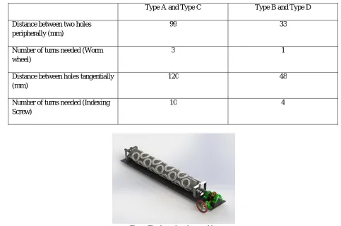
At first, the prototype was designed in Solid WORKS considering the design parameters and constraints. Each part of the model was created and then assembled, Fig a. shows the final assembly of the prototype. The different components used in this fixture is listed below:
1) Gearbox
2) Flange
3) Clamps
4) Lead screw
5) Bearing block
6) Roller wheels
7) Roller (workpiece)
Fig b. shows that, how the workpiece will be clamped on the fixture. The clamps will be able to restrain the motion of workpiece in Y-direction during the drilling operation. The flange, which can be seen in fig c. connects the workpiece shaft to the gearbox. The gearbox gives rotary motion to the workpiece while the lead screw gives translatory motion the fixture bed, refer fig d. Indexing Mechanism: -The need to mark holes would be completely removed as the worm assembly and indexing screw would index all holes peripherally and also tangentially respectively. The worm ratio is 18:1 which means 18 turns of worm gear would result into one rotation of shaft. Indexing screw has pitch of 12mm. Roller Type A and Type C will have same indexing mechanism and type B and Type D will have same. The worm wheel turns per hole is given in table below: -
Type A and Type C Type B and Type D
Distance between two holes peripherally (mm)
99 33
Number of turns needed (Worm wheel)
3 1
Distance between holes tangentially (mm)
120 48
Number of turns needed (Indexing Screw)
[image:3.612.61.544.403.723.2]10 4
Figb: Clamp
[image:4.612.199.415.557.733.2]Fig c: Flange
Fig d: Lead screw attached to the bed
B. Analysis
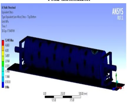
[1] The part was analyzed using ANSYS 17.1 Static structural analysis in which an axial force of 142.76N. The axial force was calculated on the basis of drill bit-5.2mm diameter and feed rate of 0.2mm/rev. The initial conditions of the part were: the shaft ends of the roller were kept stationary having all degrees of freedom fixed. Max. Equivalent stress inferred form analysis was 5.2495 MPa and Max. Deformation was 0.0028403mm.
Equivalent von-mises stresses
C. Fabrication
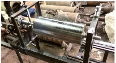
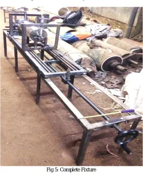
[image:5.612.201.412.82.190.2]The workpiece clamped in the fixture is seen in fig 1.and the stationary clamp is shown in fig 2. On the other side, a movable clamp is provided so that different lengths of workpiece can be mounted. The guide ways and moveable clamp is shown on fig 3. Lead screw provides the translatory motion to the fixture and the bed moves on the wheels which can be seen in fig 4. The travel length is 1200mm for the lead screw.
[image:5.612.210.403.274.379.2]Fig 1: Workpiece mounted on clamps
Fig 2: Stationary clamp
[image:5.612.198.414.285.731.2]Fig 4: Wheels for translatory motion of bed
Fig 5: Complete Fixture
III. TABLESANDCALCULATION
A. Types Of Rollers Taken For Study
There are wide variety of roller size and dye size that are in use but the calculation and study of each specific case would be tedious and impertinent. Hence, we chose the combination for four cases with maximum and minimum roller lengths concocted with maximum and minimum dye sizes. They are as follows:
1) Type A-Roller Length=800mm
Dye length=99mm
2) Type B-Roller Length=800mm
3) Type C-Roller Length=1250mm Dye Length=99mm
4) Type D-Roller Length=1250mm
Dye Length=33mm
Time study [2]
Roller types Total holes to be
drilled in rotational axis (M)
Total holes to be in axial axis (N)
Total holes to be drilled (M*N)
A 6 6 36
B 18 12 216
C 6 9 54
D 18 24 432
Time study before installing fixture [3]:
Roller types Time taken for
marking T1A
(min.)
Time taken for work fixing T2A
(min.)
Time taken to drill all holes T3A
(min.)
Total time taken TA=T1+T2+T3
(min.)
A 24 8 41 73
B 116 8 235 359
C 40 11 71 122
D 223 11 450 684
Time study after installing fixture: Roller types Time taken for marking T1B (minutes) Time taken for work fixing T2B
(min.)
Time taken to drill all holes T3B (min.)
Total time taken TB=T1+T2+T3
(min.)
Time Saved (TA-TB)
A 0 8 49 57 16
B 0 8 251 259 100
C 0 11 71 82 40
B. Cost Analysis
The cost of manufacturing one roller was calculated with and without fixture.
Cost Analysis before installing fixture
Roller types Number of
labors required
Cost of labor (Rs./Hour)
Total time taken TA
(hours)
Total Cost CA (Rs.)
A 1 62.5 1.21 75.62
B 1 62.5 5.98 373.75
C 2 62.5 2.03 253.75
D 2 62.5 11.4 1425
Cost Analysis after installing fixture
Roller types No. of labors
reqd.
Cost of labor (Rs./Hour)
Total time taken TB (min.)
Total Cost CB (Rs.) Cost saved per roller CA-CB (Rs):
A 1 62.5 0.95 59.37 16.245
B 1 62.5 4.31 269.37 104.37
C 1 62.5 1.36 85 168.75
D 1 62.5 8.15 509.37 915.62
IV. CONCLUSION
The data analysed above depicts that the fixture is most effective when the length of roller is highest i.e. 1250mm and the holes to be drilled along the PCD are at near distance i.e. 33mm. From time study table and cost study table it is clearly evident that total time of production and cost will reduce after using the fixture. Analyzing all the four cases it is inferred that there is an average reduction of 45.03% of cost after using the fixture.
V. ACKNOWLEDGMENT
We would like to acknowledge Gayatri machine works and Utsavpapad machine for providing their support and cooperation in fabrication of the Fixture. Special thanks to Yamuna Machine Works for their financial support in purchasing necessary materials for the fixture.
REFERENCES
A. Journal Papers
[1] Sangamesh, V. V. Kulkarni, Design and Fabrication of Indexing Set Up for Drill Jig, International Research Journal of Engineering and Technology (IRJET),
Volume: 03 Issue: 06, June-2016. [1]
[2] PatangeVidyut Chandra, An effort to apply work and time study techniques in a manufacturing unit for enhancing productivity, International Journal of Innovative Research in Science, Engineering and Technology,Vol. 2, Issue 8, August 2013. [2
[3] AshishMourya, ChandrashekharPatil, PriyankaChavan, ManjurSande, SarangPisal,automatic indexing mechanism for drilling machine, International
Conference on Emerging Trends in Technology, Science and Upcoming Research in Computer Science, ISBN: 978-81-931039-3-7. [3]
(India) Jigs and Fixtures, Third Edition
[2] Jigs and Fixtures – IGNOU
[3] Industrial Engineering and management – O.P Khanna
[4] Design of machine elements – V.B Bhandari
[5] Colvin, F. H.; Haas, L. L. (1938). Jigs and Fixtures: A Reference Book. New York and London: Mcgraw-Hill Book Company.