International Journal of Emerging Technology and Advanced Engineering
Website: www.ijetae.com (ISSN 2250-2459, ISO 9001:2008 Certified Journal, Volume 6, Issue 7, July 2016)
58
Dynamic Performance Improvement of Oscillating Motor for
Linear Compressors
Gyu-Sik Kim
11
Dept. of Electrical and Computer Eng., Univ. of Seoul, Korea
Abstract—The dynamic performance of oscillating motor for linear compressors is improved via efficient motor parameter identification and piston position estimation. Also, a closed-loop sensorless stroke control system for an oscillating linear motor has been designed. The motor parameters are identified as a function of the piston position and the motor current. They are stored in ROM table and used later for the accurate estimation of piston position. Some experimental results are given in order to show the feasibility of the proposed control schemes for linear compressors.
Keywords— Oscillating motor, Linear compressor, Parameter identification, Piston position estimation, Sensorless stroke control
I. INTRODUCTION
Many countries such as the U.S., the EU, and Japan have some kind of energy regulation programs to decrease the energy consumption of electric home appliances. In a house, a refrigerator consumes about 30% of the total electric energy and the compressor which circulates the refrigerant through the refrigeration system consumes most of the electric energy in a refrigerator. Hence, energy efficient compressors are essential to the saving of household electric energy.
The compressor is one of the essential components of a refrigerator, together with the evaporator, condenser and expansion valve. The compressor draws in low-pressure gas-phase refrigerant from the evaporator and discharges it in the high pressure-liquid state to the condenser. The conventional reciprocating compressor in which a crank-shaft mechanism converts the motor’s rotary motion into reciprocating motion to draw in and discharge refrigerant is lower efficient than the linear compressor. On the other hand, the linear compressor, where a linear motor directly drives a piston in a back and forth motion to change the control volume and pressure, has come into wide use.
A linear compressor has an oscillating linear motor coupled to a resonating mechanical system: a piston and a spring. The advantages of this compressor when compared to a standard reciprocating compressor are a high reduction of energy losses and a variable cooling capacity.
Over the past several decades, a series of linear compressors have been developed for various applications in order to meet the need for efficient compressors[1-7].
One of the major advantages of a linear compressor is that it is oil-free. The lubrication is provided by gas bearings on the cylinder wall and a piston support mechanism which allows contact free oscillation of the piston. This enables usage with refrigerants which would be degraded over time due to contact with oil. It also provides extremely quiet long life operation. Furthermore, the amplitude of the oscillation and the mean position of the piston can be controlled allowing the refrigeration system to maintain a high coefficient of performance under partial load conditions.
It has been shown that linear compressors have extremely low friction losses compared to other compressor types and that a high efficiency can be achieved for a variety of refrigerants and compressor sizes[1]. The problems associated with linear motor configurations which are potentially applicable to linear compressors have been discussed[2]. They described moving coil type and moving magnet type linear motors and two methods of linear compressor control that have been successfully applied. Some non-refrigeration applications for linear compressors have also been studied[3]. A small linear compressor which operates at 50Hz was designed for the European market which could serve a variety of small and portable coolers for specialty uses, including recreational and medical cooling[4]. The piston positioning accuracy and the efficiency of a sensorless linear compressor system with a linear pulse motor were examined using analytical and experimental approaches[5]. However, the motor parameters were not identified fully. A dual stroke and phase control system was proposed for the linear compressors of a split-stirling cryocooler[6]. A linear compressor was developed for a 680 liter household refrigerator[7]. It reduced the energy consumption of a refrigerator by 47% when compared with a reciprocating compressor.
International Journal of Emerging Technology and Advanced Engineering
Website: www.ijetae.com (ISSN 2250-2459, ISO 9001:2008 Certified Journal, Volume 6, Issue 7, July 2016)
59 In order to estimate the piston position accurately, motor parameters are identified as a function of the piston position and the motor current. Experimental results have been obtained in order to show the feasibility of the proposed control scheme for linear compressors.
II. CONTROL OF OSCILLATING MOTORS
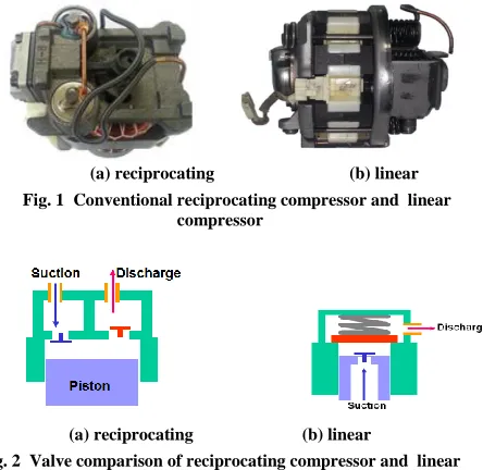
Fig. 1(a) shows the conventional reciprocating compressor driven by a rotary motor coupled to a conversion mechanism. On the other hand, a linear compressor is a piston-type compressor in which the piston is driven directly by a linear motor as shown in Fig. 1 (b). Because all the driving forces in a linear compressor act along the line of motion, there is no sideways thrust on the piston. The compressor of this type substantially reduces sliding bearing loads. Thus, no need for the conversion mechanism and no sideways thrust make a linear compressor more efficient than a reciprocating compressor. In addition, the sudden peak noises which are generated as a reciprocating compressor is turned on and off can be eliminated in a linear compressor by virtue of the soft start-stop operation. Fig. 2 shows the valve comparison of reciprocating compressor and linear compressor[7]. This linear type of valve structure shown in Fig. 2 (b) has less flow resistance and less suction gas heating comparing with the reciprocating one shown in Fig. 2 (a).
(a) reciprocating (b) linear Fig. 1 Conventional reciprocating compressor and linear
compressor
[image:2.612.338.559.138.333.2](a) reciprocating (b) linear
Fig. 2 Valve comparison of reciprocating compressor and linear compressor
[image:2.612.345.554.217.522.2]Fig. 3 Mechanical structure of a linear compressor
Fig. 4 Operating principle of a linear motor
The mechanical structure of the linear compressor studied in this research is shown in Fig. 3. The linear motor in a linear compressor can be controlled by adjusting the mean voltage of the applied AC voltage by using simple Triac based electronic circuits or inverter systems for better performance. The operating principle of a linear motor is shown in Fig. 4. The magnetic field grows to be maximum in a counterclockwise direction as the AC current increases to a positive peak value. (see ⓐ of Fig. 4) This magnetic field forces the magnet to move to the left, reaching the leftmost position finally as the AC current decreases to zero. (see ⓑ of Fig. 4)
Current i
Magnetic Field
●
N
S S
N
●
●
x x
S N S
N N
S x
ⓑ
ⓒ
ⓓ ⓐ
ⓐ ⓑ ⓒ ⓓ
Time
S N
S N
S N
[image:2.612.351.546.356.529.2] [image:2.612.67.289.452.668.2]International Journal of Emerging Technology and Advanced Engineering
Website: www.ijetae.com (ISSN 2250-2459, ISO 9001:2008 Certified Journal, Volume 6, Issue 7, July 2016)
60 Immediately, the AC current flows in the opposite direction, resulting in a clockwise magnetic field which forces the magnet to move to the right. (see ⓒ of Fig. 4) Finally, the magnet reaches the rightmost as the AC current becomes zero again. (see ⓓ of Fig. 4)
If the current is 60Hz AC, then the magnet will oscillate sixty times a second. The larger the amplitude of the AC current is controlled to be, the larger the amplitude of vibration of the magnet becomes, resulting in the larger linear speed of the piston attached to the magnet and the larger flow rate of refrigerant in a linear compressor. As can be seen from Fig. 1 (a), the conventional reciprocating compressor uses a crank mechanism in order to change the rotational motion of motors into the linear motion. Accordingly, the reciprocating compressor can be operated safely by virtue of the crank mechanism, even though it makes the reciprocating compressor less efficient.
On the other hand, the moving parts of a linear compressor are not constrained. Thus, implementation of a closed-loop control system is necessary for the accurate control of piston position. This control system needs the information of piston position. In order to measure the piston position, an inductive position sensor in which the inductor is a small stationary coil wound on a ferrite coil can be used. However, this position sensor is more expensive than a current sensor or a voltage sensor. It is also hard to install a position sensor in a linear compressor. Hence, it is more desirable to estimate the piston position indirectly.
An estimate of the piston position can be calculated indirectly.
[image:3.612.359.488.155.245.2]The equivalent electrical circuit of a linear motor in a linear compressor can be modeled as shown in Fig. 5.[8]
Fig. 5 Equivalent electrical circuit model of a linear motor
From the circuit model of Fig. 5, one can obtain the linear differential eq. (1). The thrust force Fe(t) can be
expressed in eq. (2).
) ( ) ( ) ( ) (
t v t i R dt
t di L dt
t dx
e
e
(1)
) ( ) (t i t
Fe (2) Since the magnetic flux density varies depending on the piston position, the motor parameters
andL
e arefunctions of the piston position. The effective resistance
R
eis assumed to be a constant because its variance is so small as to be ignored.
v
(
t
)
is the applied voltage to the linear motor,i
(
t
)
is the current flowing through the winding coil, andx
(
t
)
is the piston position. Rearranging eq. (1), one obtainsFrequency Command Frequency Command
Stroke Command
Stroke Command L-Comp
PID Controller PID Controller
Input voltage
Voltage Sensor Voltage
Sensor
Current Sensor Current
Sensor Stroke Estimation
Stroke Estimation ×
Motor Parameters
Motor Parameters
H/W S/W
Stroke Reference
Input frequency
Load Conditions
[image:3.612.72.553.496.701.2]Load Conditions
International Journal of Emerging Technology and Advanced Engineering
Website: www.ijetae.com (ISSN 2250-2459, ISO 9001:2008 Certified Journal, Volume 6, Issue 7, July 2016)
61
1 () () () ) ( t i R dt t di L t v dt t dx e e
(3)
The estimated value of the piston position can be attained by integrating eq. (3).
t d d dx t x 0 ) ( ˆ
t ee i t
L d i R v
0 ( ) ( ) ()
1
(4)
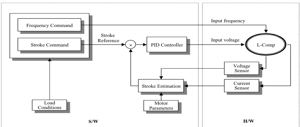
Fig. 6 shows the block diagram of the closed-loop sensorless stroke control system for a linear compressor. The applied voltage
v
(
t
)
and the motor currenti
(
t
)
are measured and input to DSP (Digital Signal Processor) CPU chips after A/D conversion. These measured variables, together with motor parameters, are used to estimate the piston position as shown in eq. (4). The estimated stroke is compared with the set-point value of stroke which is determined depending on load conditions. The output of the PID controller is the set-point value of the magnitude of the applied voltagev
(
t
)
. The frequency ofv
(
t
)
is assumed to be a constant.As mentioned earlier, the motor parameters vary depending on the piston position. Therefore, if one assumes that the motor parameters are constant, then the estimated piston position expressed in eq. (4) will have some errors, resulting in deterioration of the dynamic performance of the closed-loop control system in Fig. 6. The motor parameters
andL
ewhich have substantial influence on the closed-loop control system should be identified as a function of piston position and motor current, stored in ROM table and used for an accurate estimation of piston position. From eq. (3), one obtains :
x t Lei t
t v Rei d0[ ( ) ( )]
) ( ˆ ) (
ˆ (5)
Note that
x
(
t
)
,i
(
t
)
andv
(
t
)
in eq. (5) are the measured values using a position sensor, a current sensor, and avoltage sensor, respectively. Note also that
ˆ
andL
ˆ
earethe identified values of
andL
e, respectively.Let
t
n be a period of the piston moving linearly in thesteady state. Dividing
t
ninto n equal time intervals such as 0,t
1,t
2, ... ,t
n1,t
n, one can get eq. (6) using eq. (5).
n t e n e n t e e t e ed
i
R
v
t
i
L
t
x
d
i
R
v
t
i
L
t
x
d
i
R
v
t
i
L
t
x
0 0 2 2 0 1 1)]
(
)
(
[
)
(
ˆ
)
(
ˆ
)]
(
)
(
[
)
(
ˆ
)
(
ˆ
)]
(
)
(
[
)
(
ˆ
)
(
ˆ
2 1
(6)Rearranging eq. (6) in a matrix form, one can obtain :
b L A e ˆ ˆ
(7)where n x 2 matrix A and n x 1 vector b are given as
)
(
)
(
)
(
)
(
)
(
)
(
2 2 1 1 n ni
t
t
x
t
i
t
x
t
i
t
x
A
,
n t e t e t ed
i
R
v
d
i
R
v
d
i
R
v
b
0 0 0)]
(
)
(
[
)]
(
)
(
[
)]
(
)
(
[
2 1
(8)Using pseudo inverse manipulation, one can obtain eq. (9) from eq. (7).
b A A A L T T e 1 ) ( ˆ ˆ
(9)III. EXPERIMENTAL RESULTS
A sensorless controller for linear compressors has been implemented as shown in Fig. 7. The CPU chip was a TMS320C2000 and a Triac-based simple drive system was chosen for a more cost-effective design. For the experimental study, a 2.2kW linear compressor is chosen. This compressor was developed for application to air conditioners. The set-point value of the stroke was 16mm. The frequency of the voltage was set to be 60Hz. Fig. 8 shows the experimental results for the applied voltage
v
(
t
)
.International Journal of Emerging Technology and Advanced Engineering
Website: www.ijetae.com (ISSN 2250-2459, ISO 9001:2008 Certified Journal, Volume 6, Issue 7, July 2016)
[image:5.612.55.563.86.734.2]62
Fig. 7 Experimental set up for sensorless controller
(a) Voltage waveform at start operation
(b) Voltage waveform at steady state
[image:5.612.303.557.134.719.2](c) Voltage waveform with low pass filter x axis : 5 [msec/div]
Fig. 8 Experimental results for the applied voltage
v
(
t
)
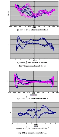
(a) Plot of
ˆ
as a function of strokex
[image:5.612.97.255.134.255.2](b) Plot of
ˆ
as a function of currenti
Fig. 9 Experimental results for
ˆ
(a) Plot of
L
ˆ
e as a function of strokex
(b) Plot of
L
ˆ
e as a function of currenti
Fig. 10 Experimental results for
L
ˆ
e50 55 60 65 70 75
-0.010 -0.008 -0.006 -0.004 -0.002 0.000 0.002 0.004 0.006 0.008 0.010
stroke [m]
alpha [N/A]
190 195
50 55 60 65 70 75
-10 -8 -6 -4 -2 0 2 4 6 8 10
current [A]
alpha [N/A]
195V
0.09 0.10 0.11 0.12 0.13
-0.010 -0.008 -0.006 -0.004 -0.002 0.000 0.002 0.004 0.006 0.008 0.010
stroek [m]
L [H]
190V 195V
0.09 0.10 0.11 0.12 0.13
-10 -8 -6 -4 -2 0 2 4 6 8 10
current [A]
L [H]
[image:5.612.52.281.284.687.2]International Journal of Emerging Technology and Advanced Engineering
Website: www.ijetae.com (ISSN 2250-2459, ISO 9001:2008 Certified Journal, Volume 6, Issue 7, July 2016)
[image:6.612.54.278.228.342.2]63 Fig. 11 shows the experimental results for various load changes. As the load increased, the stroke command was changed from 14mm to 15mm and then to 16mm. At the same time, the PD (compressor discharge pressure) and the PS (compressor suction pressure) was changed for various load tests. One found that this compressor could be controlled with some errors for various loads.
Fig. 11 Experimental results for load changes
IV. CONCLUSIONS
In this paper, the dynamic performance of oscillating linear motors, which are used in household refrigerators, are improved by means of efficient parameter identification. A closed-loop sensorless stroke control system for a linear compressor has been designed. The oscillating linear motor parameters are identified as a function of the piston position and the motor current. Then, they are stored in ROM table and used for an accurate estimation of piston position later. Experimental studies have demonstrated that the identified motor parameters are practical for sensorless stroke control of a linear compressor.
Acknowledgement
This work has been supported by 2006 haksul program (2006-E-EL03-P-01), which is funded by The Korea Energy Management Corporation
REFERENCES
[1] Reuven Unger, “Linear compressors for non-CFC refrigeration,” Proceedings International Appliance Technical Conference, May 13-15, 1996, Purdue University, West Lafayette, Indiana, USA [2] Robert Redlich, Reuven Unger, Nicholas van der Walt, "Linear
compressors : motor configuration, modulation and systems," Proceedings International Compressor Engineering Conference, July 23-26, 1996, Purdue University, West Lafayette, Indiana, USA [3] Reuven Unger, "Linear compressors for clean and specialty gases,"
Proceedings International Compressor Engineering Conference, July 14-17, 1998, Purdue University, West Lafayette, Indiana, USA [4] Reuven Unger, "Development and testing of a linear compressor
sized for the european market," Proceedings International Appliance Technical Conference, May 10-12, 1999, Purdue University, West Lafayette, Indiana, USA
[5] Masayuki Sanada, Shigeo Morimoto, and Yoji Takeda, "Analyses for sensorless linear compressor using linear pulse motor," Proceedings Industry Applications Conference, pp. 2298-2304, Oct., 3-7, 1999 [6] Yee-Pien Yang and Wei-Ting Chen, "Dual stroke and phase control
and system identification of linear compressor of a split-stirling cryocooler," Proceedings Decision and Control, pp. 5120-5124, Dec. 7-10, 1999
[7] Gye-young Song, Hyeong-kook Lee, Jae-yoo Yoo, Jin-koo Park, and Young-ho Sung, "Development of the linear compressor for a household refrigerator," Proceedings Appliance Manufacturer Conference & Expo, September 11-13, 2000, Cincinnati, Ohio, USA
[8] Cadman, R. V.(1967), “A Technique for the Design of Electrodynamic Oscillating Compressors,” Ph.D.Thesis, Purdue Univ.
13.5 14.0 14.5 15.0 15.5 16.0
3 4 5 6 7 8
current[A]
stroke[mm]