International Journal of Emerging Technology and Advanced Engineering
Website: www.ijetae.com (ISSN 2250-2459,ISO 9001:2008 Certified Journal, Volume 5, Issue 11, November 2015)
43
Adaptive Channel Equalizer using Combination of FIR and
Functional Link Artificial Neural Network for Complex Signals
Rajesh Prakash Joshi
1, Sanjay Mathur
2, Manisha Kandpal
31Asst Professor, Dept. of Electronics & Communication Engineering, B.T Kumaon Institute of Technology, Dwarahat,
Uttarakhand, India
2Asst Professor, 3Teaching Personnel, Dept. of Electronics & Communication Engineering, G.B.P.U.A & T, Pantnagar,
Uttarakhand, India
Abstract− This paper proposes an adaptive nonlinear
channel equalizer by using combination of finite impulse response (FIR) filter and functional link artificial neural (FLANN) network (CFFLANN) capable of equalizing complex multilevel signals. The equalizer is designed to remove linear and nonlinear distortion produced by nonlinear channel. FLANN section removes the nonlinear distortions and FIR section removes linear distortions. Equalizer uses modified least mean square (MLMS) algorithm to adapt its tap weights. This system has less complex structure and high convergence speed. Performance of the equalizer is evaluated by two parameters-mean square error (MSE) and bit error rate (BER).
Keywords− Adaptive equalizer, finite impulse response
(FIR) filter, functional link artificial neural network (FLANN), nonlinear channel.
I. INTRODUCTION
In digital data transmission over a communication channel, various types of distortions like ISI caused by dispersive channel, the nonlinearity introduced by modulation and demodulation process and noise, put adverse effect. To overcome these distortions, various equalizing techniques including linear and nonlinear equalizers have been reported in recent years. Due to the simple structure and fast convergence speed, linear channel equalizer based on finite impulse response (FIR) or lattice structure is widely used. But the performance of the linear equalizers is limitedespecially when the nonlinear distortions exist. In such case, the nonlinear equalizers based on nonlinear signal processing may be used with the benefits of lower bit error rate (BER), lower mean squared error (MSE), and higher convergence rate than those of the linear equalizers.
Researchers proved that Neural networks (NNs) are the systems that can perform complex mapping between its input and output space and are capable of forming complex decision regions with nonlinear decision boundaries. Furthermore, due to nonlinear characteristics of the NN, networks of different architectures have been successfully applied in channel equalization.
International Journal of Emerging Technology and Advanced Engineering
Website: www.ijetae.com (ISSN 2250-2459,ISO 9001:2008 Certified Journal, Volume 5, Issue 11, November 2015)
44
Various applications of the FLANN, modified FLANN decision feedback architecture, and FLANN cascaded with Chebyshev orthogonal polynomial (FLANNCP-AE) have been reported for functional approximation, nonlinear system identification, and channel equalization by Zhao and Zhang (2008). It has been shown that BER and MSE performance of the FLANN-based equalizer is superior to other NN structures such as MLP and PPN under wide variation of Eigenvalue ratio (EVR) and signal-to-noise ratio (SNR) conditions for both linear and nonlinear channel models in the case of PAM or QAM. An adaptive equalizer is proposed by Zhao and Zhan (2009) in which combination of FLANN and FIR filter is used to compensate linear and nonlinear distortions in nonlinear communication channel. They proposed the adaptive equalizer for two level signals. The information rate through a channel can be increased by increasing the bandwidth and the associated symbol rate. And if the channel bandwidth is to remain fixed, then the only option to increase the information rate for limited bandwidth is to increase the amount of information encoded in a symbol i.e. to increase the number of level of signal.A data stream s(k) is transmitted from the transmitter and is corrupted due to the channel characteristics and also deformed by additive White Gaussian noise. The channel impulse response h(k) considered in this study is expressed as follows
( ) { { [
( )]}
(1)
The corrupted signal x(k) is feed to equalizer input to remove the distortion produced. If M is the number of distinct signal levels, then each symbol carries log2M bits of information, and the overall information rate rises to 2B log2M. So, multilevel signals are used where high information transfer rate is required over low bandwidth channels. Therefore this paper proposed an adaptive equalizer capable of equalizing multilevel complex signal using CFFLANN. Results for the equalization process of 4-level complex signals are shown in this paper. The basic question which arises in mind quickly as soon someone talk about complex signal processing is that even all physical signals and waveforms are real valuedso why bother to consider complex-valued signals and systems? Complex signal notions have two important viewpoints or implications: communication theory view radio implementation view:
A. Communication theoretic aspects
Most spectrally efficient in phase and quadrature
phase (I/Q) modulation techniques
(complexmodulation, radio waveforms) are based on complex signal processing.
For modeling of the radio channel and receiver signal processing for equalization and detection.
B. Radio implementation aspects
All advanced frequency translation techniques and thus the related receiver architectures (low-intermediate frequency, direct-conversion, etc.) utilize complex signals.
Fig.1: Nonlinear equalization model for nonlinear channel.
For Sampling and efficient filtering of band pass signals.
II. COMBINATION OF FIRAND FLANN(CFFFLANN)
It is a combination of FLANN and FIR. Both the parts are combined adaptively. This combined network is named as CFFLANN. In this paper this network is used to equalize 4-level (randomly selected 1+i,1-i,-1-i,-1+i) complex signal x(k). The input of the equalizer is m dimensional input. A data stream x (k) and its m-1 delayed are feed to the first block of the equalizer. This is a functional expansion block. This block expands the m dimensional input to 1+3m+mc
2 output i.e. this expanded function block comprises a subset of orthogonal sin and cos functions, the original pattern and the outer product to model nonlinear channel. For example consider m=3, inputs are u1, u2, u3 the corresponding output of this block will be X(k)=[1 u1 cosπu1 sinπu1 u2 cosπu2 sinπu2 u3 cosπu3 sinπu3 u1×u2 u1×u3 u2×u3]. It has lower complexity due to the absence of any hidden layer and the adaptive algorithm is more easily used to train this network. Consider a set of basis functions B= {ψi(k)}, where iϵI ,I={1,2,3…………}and k is time index. Let BN1=*ψϵ + , be a set of basis
International Journal of Emerging Technology and Advanced Engineering
Website: www.ijetae.com (ISSN 2250-2459,ISO 9001:2008 Certified Journal, Volume 5, Issue 11, November 2015)
45
Fig.2: CFFLANNAssume a new vector RX(k)=[x(k) x(k-1)……..x(k-N2+1)]T is the input to the FIR subsection and W1(k)=[w1(k) w2(k) ……….w N1 (k)]T and W2(k)=[w N1+1 (k) w N1+2(k) ……….w N1+ N2 (k)]Tare the tap weight vectors of FLANN and FIR subsections respectively. The output of the FLANN subsection is added to the output of the FIR subsection. Therefore the overall output y(k)=λ(k)z(k)+(1- λ(k))z1(k), where λ(k) is a convex combination parameter. The value of λ(k) lies between 0 and 1, these two extreme value corresponds to pure FIR filter and pure FLANN equalizer respectively. λ(k) is adjusted adaptively so that this equalizer can shift adaptively from one extreme to other to handle linear and nonlinear channel distortions. Initially the value of λ(k) is kept very small and the equalizer converges faster due to large error. Real part and imaginary part of the signal is processed together in parallel fashion. The processing is completely separate from one another, finally these two parts are recombined then compared with desired signal. Error signal is also a complex number. The real part of this signal is feed to the subsection handling the real part of the received signal and the imaginary part is feed to corresponding. Equalization is same as in case of real valued signals if imaginary and real parts of the complex signal are treated as two different signals. This CFFLANN uses modified least mean square algorithm to adapt its tap weights.
III. MODIFIED LEAST MEAN SQUARE ALGORITHM
(MLMS)
MLMSis similar to LMS algorithm except an additional momentum term is added in this modified algorithm for fast convergence. Let E(k)=-(1/2)(e(k))2, where E(k) denotes an Instantaneous error, and error signal e(k) is defined as the difference between desired signal d(k) and the output signal y(k).
e(k)=d(k)-y(k) (2) where
y(k)=λ(k)γ(k)S(W1(k)TX(k))+(1-λ(k))W2(k)TRX(k) (3) According to LMS algorithm the update equations of W1(k) and W2(k) of CFFLANN are given by
W1(k+1)=W1(k)+η1δ1(k) (4) W2(k+1)=W2(k)+η2δ2(k) (5) Where
δ1(k)=e(k)λ(k)γ(k)S’(k)X(k) (6)
δ2(k)= ( ) ( )=e(k)(1-λ(k))RX(k) (7)
To increase the convergence speed of the system update equations are modified as follows
W1(k+1)=W1(k)+η1δ1(k)+u1δ1(k-1) (8) W2(k+1)=W2(k)+η2δ2(k)+u2δ2(k-1) (9) Where u1 and u2 are momentum factors used to speed up the convergence rate. For parameter λ(k) and γ(k) of CFFLANN, using the gradient algorithm, the partial derivative of E(k) with respect to λ(k) and γ(k) are given by
( )
( )=-e(k)
( )
( )=-e(k)(z(k)-z1(k)) (10)
( )
( )=-e(k)λ(k)S(W1(k)
TX(k)) (11)
Correspondingly, the parameter update equations based on the gradient algorithms are derived below
γ(k+1)=γ(k)+η3e(k)λ(k)S(W1(k)TX(k)) (12) λ(k+1)=λ(k)+η4e(k)(z(k)-z1(k)) (13)
Where ηi (i=1,2,3,4) are real positive step size values of the update equation and all are supposed to be small enough to correct reception of the desired signal.
IV. CHANNEL CHARACTERISTICS OF THREE DIFFERENT
CHANNELS
Channel Transfer function in Z-transform form
International Journal of Emerging Technology and Advanced Engineering
Website: www.ijetae.com (ISSN 2250-2459,ISO 9001:2008 Certified Journal, Volume 5, Issue 11, November 2015)
46
The above three channels are considered in this paper results are carried out for these three channels. The system could be used to remove the adverse effect of any other linear or nonlinear channels also results would be quite satisfactory in every case.V. PERFORMANCE MEASURES
The performance of the equalizer is evaluated by two parameters
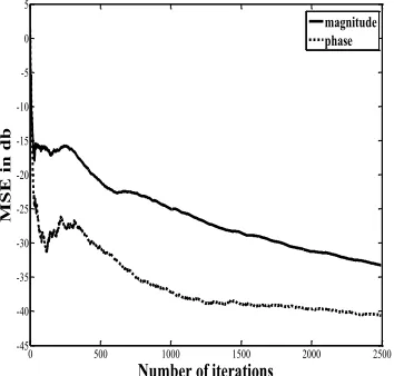
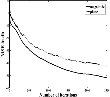
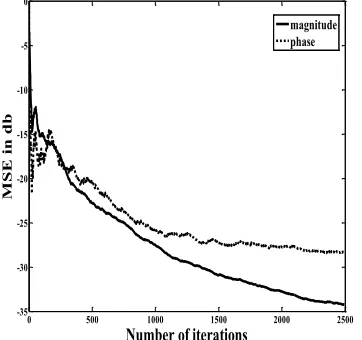
A. MSE for training the network. MSE should reduce as the training time increases and should stabilize after long. Since the complex signal is completely characterized by phase and magnitude thus two types of MSE is considered in this paper i.e. magnitude and phase MSE.
B. BER, it should also decrease as SNR increases.
VI. SIMULATION RESULTS
[image:4.612.344.533.145.316.2]The process to find MSE is carried out for SNR 15, 19 and 25. And the BER is plotted from SNR 5 to 25. Simulation results for three different channels are shown below. MSE is reducing as the number of iterations increases and BER is also reducing as SNR increases, which is desired. The main advantage of the equalizer is that the BER tends to zero even at low SNR which indicates that recovery of complex signals is very easy by using this type of equalizer.
Fig 3. MSE vs iterations for complex signal at SNR=15dB (channel1)
Fig.4. MSE vs iterations for complex signal at SNR=19dB (channel1)
[image:4.612.349.531.343.502.2]Fig 5. MSE vs iterations for complex signal at SNR=25dB (channel1)
Fig.6. Variation of BER of complex signal with different SNR values (channel1)
0 500 1000 1500 2000 2500
-45 -40 -35 -30 -25 -20 -15 -10 -5 0 5
M
SE
in
db
Number of iterations
magnitude phase
0 500 1000 1500 2000 2500
-60 -50 -40 -30 -20 -10 0
M
SE
in
db
Number of iterations
magnitude phase
0 500 1000 1500 2000 2500
-60 -50 -40 -30 -20 -10 0 10
M
SE
in
db
Number of iterations
magnitude phase
5 10 15 20 25
0 0.1 0.2 0.3 0.4 0.5 0.6 0.7 0.8
BER
[image:4.612.79.256.471.640.2]International Journal of Emerging Technology and Advanced Engineering
Website: www.ijetae.com (ISSN 2250-2459,ISO 9001:2008 Certified Journal, Volume 5, Issue 11, November 2015)
[image:5.612.352.531.146.308.2]47
Fig.7. MSE vs iterations for complex signal at SNR=15dB (channel2)[image:5.612.78.257.146.313.2]
Fig 8. MSE vs iterations for complex signal at SNR=19dB(channel 2)
Fig.9. MSE vs iterations for complex signal at SNR=25dB (channel2)
Fig.10. Variation of BER of complex signal with different SNR values (channel2)
0 500 1000 1500 2000 2500
-40 -35 -30 -25 -20 -15 -10 -5 0
M
SE
in
db
Number of iterations
magnitude phase
0 500 1000 1500 2000 2500
-60 -50 -40 -30 -20 -10 0 10
M
SE
in
db
Number of iterations
magnitude phase
0 500 1000 1500 2000 2500
-70 -60 -50 -40 -30 -20 -10 0
M
SE
in
db
Number of iterations
magnitude phase
5 10 15 20 25
0 0.1 0.2 0.3 0.4 0.5 0.6 0.7 0.8
BER
[image:5.612.353.531.347.504.2] [image:5.612.77.260.351.513.2]International Journal of Emerging Technology and Advanced Engineering
Website: www.ijetae.com (ISSN 2250-2459,ISO 9001:2008 Certified Journal, Volume 5, Issue 11, November 2015)
[image:6.612.78.259.147.317.2]48
Fig.11. MSE vs iterations for complex signal at SNR=15dB (channel3)Fig. 12. MSE vs iterations for complex signal at SNR=19dB (channel 3)
Fig.13. MSE vs iterations for complex signal at SNR=25dB (channel 3)
Fig.14. Variation of BER of complex signal with different SNR values (channel3)
0 500 1000 1500 2000 2500
-35 -30 -25 -20 -15 -10 -5 0
M
SE
in
db
Number of iterations
magnitude phase
0 500 1000 1500 2000 2500
-50 -40 -30 -20 -10 0 10
M
SE
in
db
Number of iterations
magnitude phase
0 500 1000 1500 2000 2500
-60 -50 -40 -30 -20 -10 0 10
M
SE
in
db
Number of iterations
magnitude phase
5 10 15 20 25
0 0.1 0.2 0.3 0.4 0.5 0.6 0.7
BER
[image:6.612.76.257.353.522.2]International Journal of Emerging Technology and Advanced Engineering
Website: www.ijetae.com (ISSN 2250-2459,ISO 9001:2008 Certified Journal, Volume 5, Issue 11, November 2015)
49
VII. CONCLUSION
We have developed a proper artificial neural network (ANN) model for adaptive nonlinear channel equalization for multilevel signals. The prime advantages of using ANN models are their ability to learn which is based on optimization of an appropriate error function and their excellent performance for approximation of nonlinear functions. CFFLANN is used to equalize the signals. System is capable of equalizing real as well as complex signals. Since the FLANN conations only one hidden layer thus convergence speed is very high. In addition, weights are adapted according to MLMS algorithm resulting fast convergence. Nonlinear channels produce linear (L) as well as nonlinear (N) distortions. CFFLANN have two parts
A.FLANN: To cancel the nonlinear distortions produced
by nonlinear channels.
B.FIR: To cancel the linear distortions produced by nonlinear channels.
The output of the equalizer y(k)=λ(k)z(k)+(1- λ(k))z1(k), where λ(k) is convex combination parameter. λ(k) is adaptively adjusted during the training between 0 and 1 to handle the linear and nonlinear distortions respectively. As the characteristic of the channel varies the step size varies accordingly hence adaptation in weighs dependents on channel characteristics i.e. for different channels step size is different and time dependent also.
Multilevel signals are used where high information transfer rate is required over low bandwidth channels. So, this nonlinear equalizer is designed to equalize multilevel complex signals. Transmission bandwidth is one of the precious resources in digital communication systems. To achieve better use of this resource, signals are commonly transmitted through band-limited channels. So the received signals get affected by inter symbol interference (ISI). A channel equalizer is used to recover the transmitted data from the received signals. If the nonlinearity associated with the system or channel is very high the performance of the equalizer degrades. The performance of the equalizer can be improved by increasing the SNR.
REFERENCES
[1] Abrar, S. and Nandi, A. K. [2010],“An Adaptive Constant Modulus Blind Equalization Algorithm and Its Stochastic Stability Analysis” IEEE Signal Processing letters,vol 17, no.9.
[2] Baas N. J. and Taylor, D. P. [2008],“Adaptive MLSE for DPSK in Time-and Frequency-Selective Channels” IEEE transactions on Communication, vol 53, no.9.
[3] Cha, I. and Kassam, S. A. [1995], “Channel equalization using adaptive complex radial basis function networks,” IEEE 1995.
[4] Chen, S.; Gibson, G. J. ; Cowan, C. F. N. and Grant, P. M. [1991], “Reconstruction of binary of signals using an adaptive radial-basis-function equalizer,” Signal Process., vol. 22 1991.
[5] Chen, S., Gibson, G. J. and Cowan, C. F. N. [1990], “Adaptive channel equalization using a polynomial perceptron structure,” Proc. Inst. Electr. Eng., vol. 137, no. 1.
[6] Collings, I. B. and Won, D. H. [2004] , “Performance Improvements From Decision-Delay Adaption in Adaptive MLSE Equalizers” IEEE transaction on Wireless Communications, vol.3, no. 3.
[7] García, J. A. ; Verdejo, V. G. and Figueiras-Vidal, A. R. [2005], “New Algorithms for Improved Adaptive Convex Combination of LMS Transversal Filters” IEEE 2005.
[8] Gibson, G. J. ; Sin, S. and Cowan, C. F. N. [1991], “The application of nonlinear structures to the reconstruction of binary signals”, IEEE 1991.
[9] Goh, S. L. and Mandic, D. P. [2007], “Stochastic gradient-adaptive complex-valued nonlinear neural adaptive filters with a gradient-adaptive step size,” IEEE 2007.
[10] Gong, Y. and Cowan, C. F. N. [2005], “An LMS style variable tap-length algorithm for structure adaptation” IEEE transactions on Signal Processing, vol 53, no. 7.
[11] Gong, Y. and Cowan, C. F. N. [2006], “A self-structured adaptive decision feedback equalizer” IEEE Signal Processing letters, vol.13, no.3.
[12] Haykin S. [1986] “Adaptive Filter Theory”, Prectice Hall, Englewood Cliffs, NJ. Chapter 5, pp.194-268.
[13] Inui, T. ; Komukai, T. ; Nakazawa, M. ; Suzuki, K. [2002]
“Adaptive Dispersion Slope Equalizer Using a Nonlinearly Chirped Fiber Bragg Grating Pair With a Novel Dispersion Detection Technique” IEEE Photonic Technology letters, vol. 14, no. 4.
[14] Le, M. Q. ; Hurst, P. J. and Keane, J. P. [2002], “An Adaptive Analog Noise-Predictive Decision-Feedback Equalizer” IEEE journals of Solid State Circuits vol 37, no. 2.
[15] Lin, B. S. ; Lin, B. S. ; Chong, F. C. and Lai, F. P. [2007], “Higher-order-statistics-based radial basis function networks for signal enhancement,” IEEE 2007.
[16] Mai, J. and Sayed, A. H. [2000], “A feedback approach to the steady-state performance of fractionally spaced blind adaptive equalizers” IEEE transaction on Signal Processing , vol 48,no.1. [17] Mandic, D. P. [2004], “A generalized normalized gradient descent
algorithm,” IEEE Signal Processing letters, vol 11, no. 2. [18] Pao, Y. H. [1989], “Adaptive Pattern Recognition and Neural
Networks Reading. Reading” MA: Addison-Wesley, 1989. [19] Patra, J. C. and Kot, A. C. [2002] , “Nonlinear dynamic system
identification using Chebyshev functional link artificial neural networks,” IEEE transactions on Systems, Men and Cybernetics-part B, Cybernetics, vol 32, no. 4 .
[20] Patra, J. C. and Pal, R. N. [1995], “A functional link artificial neural network for adaptive channel equalization,” Signal Process., vol. 43.
International Journal of Emerging Technology and Advanced Engineering
Website: www.ijetae.com (ISSN 2250-2459,ISO 9001:2008 Certified Journal, Volume 5, Issue 11, November 2015)
50
[22] Pavan, S. and Tiruvuru, R. [2007],“Analysis and design of singly terminated transmission-line FIR adaptive equalizers” IEEE transactions on Circuits and Systems-І, regular papers, vol.54,no.2. [23] Spinnler, B. [2010] ,“Equalizer Design and Complexity for Digital
Coherent Receivers” IEEE journal of selected topics in Quantum Electronics,vol 16 no.5.
[24] Tidestav,C. ; Ahlén, A. and Sternad M. [2001], “Realizable MIMO Decision Feedback Equalizers Structure and Design”, IEEE transaction on Signal Processing, vol 49,no.9.
[25] Valcarce, R.L. [2004], “Realizable linear and decision feedback equalizersd: properties and connections” IEEE transaction on Signal Processing, vol 52 no.3.
[26] Wei, X.; Cruickshank, D.G.M. ; Mulgrew, B. and Palou, F. R. [2007], “A Unified Approach to Dynamic Length Algorithms for Adaptive Linear Equalizer” IEEE 2007.
[27] Weiner, N. [1949]“Extrapolation, interpolation and smoothing of stationary time series with Engineering Applications” MIT press,vol 15,Cambridge,MA,1949.
[28] Yang, S. S. ; Ho, C. L. and Lee, C. M. [2006], “HBP: Improvement in BP Algorithm for an Adaptive MLP Decision Feedback Equalizer” IEEE 2006 transacation on Circuits and VOL. 53 [29] Yee, M. S. and Hanzo, L.[2002]“A wide-band radial basis function
decision feedback equalizer-assisted burst-by-burst adaptive modem” IEEE transaction on Communicatons, vol 50,no.5. [30] Zhao, H. Q. and Zhang, J. S. [2008]“Functional link neural network
cascaded with Chebyshev orthogonal polynomial for nonlinear channel equalization,” Signal Process., vol. 88, pp. 1946–1957, 2008.