International Journal of Emerging Technology and Advanced Engineering
Website: www.ijetae.com (ISSN 2250-2459, ISO 9001:2008 Certified Journal, Volume 9, Issue 4, April 2019)
127
Structural Design and Verification of 3U Cubesat Structure
using CFRTP/PEEK Material
Bui Nam DUONG
1, Kei-ichi OKUYAMA
2, Truong Xuan HUNG
3, Nguyen Duc Minh
4, Trinh Thang LONG
5,
Nguyen Tien SU
6, Nguyen Dinh Chau MINH
71,3,4,5,6,7Vietnam National Space Center, Vietnam Academy of Science and Technology, Hanoi, Vietnam
2Department of Applied Science for Integrated System Engineering and Laboratory of Spacecraft Environment Interaction
Engineering Graduate School of Engineering, Kyushu Institute of Technology, Kitakyushu, Japan
Abstract—Traditional satellite structure is normally made of aluminium alloys, e.g. 7075, 6061-T6, 2024-T4 etc. They are very strong and stiffness, but its weight sometimes limits the mass budget for the satellite's mission. Modern design has changed by used other innovated materials, such as CFRP, CFRTP etc. It is able to mass-saving, good temperature resistance, good strength-to-weight ratio, rigidity etc and simplify the structure of satellite somehow. A simple 3U Cubesat structure, using the CFRTP/PEEK material, is designed to demonstrate the application of this material. After being designed, the structure is manufactured and verified by both computational analysis and environmental test method. The calculated natural frequency and random analysis are compared to modal survey test, random vibration test to validate the calculated MS (margin of safety) of the structure. This paper describes structural design and methods, which are used to verify the structure, including finite element analysis and environmental test. The analysis and test results are also presented and evaluated in detail to ensure the survivability of the structure under the launching requirement.
Keywords— Structural Design, Verification, Carbon Fiber
Reinforced Thermo-Plastics/PEEK (CFRTP/PEEK)
I. INTRODUCTION
The structural design and verification are complex process. It is usually done during the development phase, starting from the required definition of rocket, subsystem, preliminary structural design, finite element analysis, manufacture and environmental test. This paper describes the structural design and methods used for verifying the 3U Cubesat structure, using CFRTP/PEEK with the results of the finite element analysis, and conducts environmental testing to ensure survivability under the launching requirement.
II. STRUCTURAL MODEL
The structural model was designed by CAD software and is analysed to determine the natural frequency, its structural characteristics and margin of safety factor, etc.
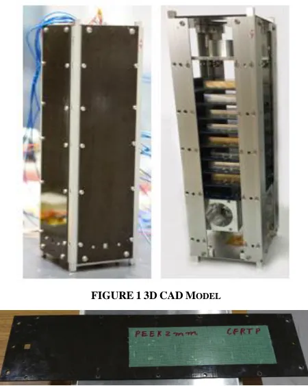
After that, the model is manufactured, fully assembled and integrated as shown in Fig. 1. It has the rails structure made by aluminium alloy, surrounded by CFRTP/PEEK material panels with the dimension is 328mmx100mmx2mm. There are dummy PCB circuit boards, PC/104 modules, dummies mass, etc that placed inside. Top panel, bottom panel, PCB circuit boards, PC104 modules to be connected or stacked together. The model dimensions are compliant with the general standards of 3U Cubesat.
FIGURE13DCADMODEL
[image:1.612.330.555.379.661.2]International Journal of Emerging Technology and Advanced Engineering
Website: www.ijetae.com (ISSN 2250-2459, ISO 9001:2008 Certified Journal, Volume 9, Issue 4, April 2019)
128
III. MECHANICAL REQUIREMENT
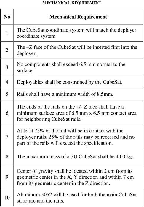
The structure integrated CFRTP/PEEK panels should fulfil the mechanical requirements of general standards for 3U Cubesat. It is show in Table 1 as below
TABLE1
MECHANICAL REQUIREMENT
No Mechanical Requirement
1 The CubeSat coordinate system will match the deployer coordinate system.
2 The –Z face of the CubeSat will be inserted first into the deployer.
3 No components shall exceed 6.5 mm normal to the surface.
4 Deployables shall be constrained by the CubeSat.
5 Rails shall have a minimum width of 8.5mm.
6
The ends of the rails on the +/- Z face shall have a minimum surface area of 6.5 mm x 6.5 mm contact area for neighboring CubeSat rails.
7
At least 75% of the rail will be in contact with the deployer rails. 25% of the rails may be recessed and no part of the rails will exceed the specification.
8 The maximum mass of a 3U CubeSat shall be 4.00 kg.
9
Center of gravity shall be located within 2 cm from its geometric center in the X, Y direction and within 7 cm from its geometric center in the Z direction.
10 Aluminum 5052 will be used for both the main CubeSat structure and the rails.
IV. TEST REQUIREMENT
The structure using the CFRTP/PEEK material should fulfil the test requirements of general standards for 3U cubesat or the launch service providers if the launcher has been selected. At the very minimum, all cubesats will undergo the following tests.
A. Modal survey vibration
Modal survey can help to determine the natural frequency of the structure and bias errors when to do random test, sine test, etc. Conditions are show in Table 2 as below
TABLE2
MODAL SURVEY TEST TABLE
Direction Frequency [Hz]
Acceleration
[Grms] Time [min]
All direction 20~2000 0.5 1
B. Random vibration
Random vibration test is performed as defined by the launch provider. Conditions are show in Table 3.
TABLE3
RANDOM VIBRATION TEST TABLE
V. STRUCTURAL VERIFICATION
After design and manufacture, the structure should be verified by taking analysis and test. They are shown in Table 4 as below
TABLE4
STRUCTURAL VERIFICATION METHOD
No Design Requirements
Verification Requirements
Verification Method
1
The CubeSat coordinate system will match the deployer coordinate system.
Make sure the coordinate system will match the deployer coordinate system.
Check in 3D CAD
2
The –Z face of the CubeSat will be inserted first into the deployer.
Make sure the –Z face of the CubeSat will be inserted first into the deployer.
Check in 3D CAD
3
No components shall exceed 6.5 mm normal to the surface.
Measure the satellite overall body dimension
Size
measurements
4
Deployable shall be constrained by the CubeSat.
Make sure the deployable shall be constrained by the CubeSat.
Check in 3D CAD
5
Rails shall have a minimum width of 8.5mm.
Measure the satellite overall body dimension
Size
[image:2.612.314.571.158.215.2] [image:2.612.47.290.201.549.2] [image:2.612.328.556.276.396.2] [image:2.612.319.569.460.715.2]International Journal of Emerging Technology and Advanced Engineering
Website: www.ijetae.com (ISSN 2250-2459, ISO 9001:2008 Certified Journal, Volume 9, Issue 4, April 2019)
129
No Design Requirements Verification Requirements Verification Method 6
The ends of the rails on the +/- Z face shall have a minimum surface area of 6.5 mm x 6.5 mm contact area for neighbouring CubeSat rails. Measure the satellite overall body dimension Size measurements 7
At least 75% of the rail will be in contact with the deployer rails. 25% of the rails may be recessed and no part of the rails will exceed the specification.
Make sure the At least 75% of the rail will be in contact with the deployer rails. 25% of the rails may be recessed and no part of the rails will exceed the specification.
Check in 3D CAD
8
The maximum mass of a 3U CubeSat shall be 4.00 kg.
Weigh the satellite body after assembly
Weight measurements
9
Center of gravity shall be located within 2 cm from its geometric center in the X, Y direction and within 7 cm from its geometric center in the Z direction.
Make sure the center of gravity is 0±2 cm, 0±2 cm, 0±7 cm (X, Y, Z) from its geometric center. Center of mass measurements 10 Aluminium 5052 will be used for both the main CubeSat structure and the rails.
Make sure the Aluminium 5052 will be used for both the main CubeSat structure and the rails.
Check in 3D CAD
11
[image:3.612.45.291.134.708.2]Should be able to survive random wave vibrations
Table 3. Random vibration test table
Random vibration, finite element analysis 12 Natural frequency should meet the launcher requirement
For H-IIA: 50 Hz (lateral) and 100 Hz (longitudinal)
Vibration test, finite element analysis
13
Margin of safety (MS) should be greater than 0 regarding all the load conditions
MS > 1 Finite element analysis
VI. RESULTS
A. Finite element analysis 1) Natural Frequency Analysis
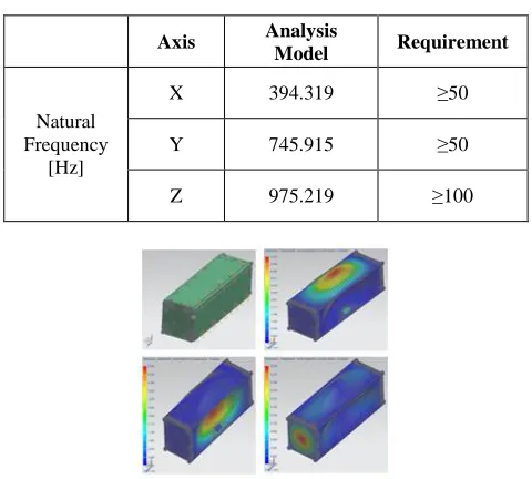
Because the satellite withstands a vibration load during the rocket launch, the inside components might be damaged from resonance if both satellite and rocket natural frequencies are very nearly equal. Therefore, it is required that the natural frequency of the satellite has to be higher than the rocket’s one. The vibration demands for a nano sub-payload to ride inside an H-IIA, considered as launcher’s reference, are more than 100 Hz in the axis direction (X-axis) and 50 Hz in the orthogonal axis direction (Y and Z axes). The first natural frequency of the satellite must satisfy this condition. Based on above discussion, the results of the structure analysis are shown in Table 5 as below
TABLE5
THE RESULTS OF NATURAL FREQUENCY ANALYSIS
Axis Analysis
Model Requirement
Natural Frequency
[Hz]
X 394.319 ≥50
Y 745.915 ≥50
Z 975.219 ≥100
FIGURE3THE RESULTS OF NATURAL FREQUENCY ANALYSIS
2) Dynamic Analysis
[image:3.612.324.564.353.569.2]International Journal of Emerging Technology and Advanced Engineering
Website: www.ijetae.com (ISSN 2250-2459, ISO 9001:2008 Certified Journal, Volume 9, Issue 4, April 2019)
[image:4.612.329.564.117.482.2]130
Figure 4 The Results Of Dynamic AnalysisB. Environmental Test
TABLE6
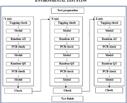
ENVIRONMENTAL TEST FLOW
Environmental test conducted at the Center for Nanosatellite Testing of the Kyushu Institute of Technology. Environmental test is used for verifying if the manufactured structure can be withstood the simulated launching condition. Environmental test flow is show in Table 6.
Figure 5 Setting The Vibration Test
Figure6THE VIBRATION TEST
Modal survey tests should be done after each vibration test to determine the structure natural frequency The results of the Modal survey test are shown in Table 7.
TABLE7
THE RESULTS OF MODAL SURVEY TEST
Axis Analysis
Model Requirement
Natural Frequency
[Hz]
X 394.319 ≥50
Y 745.915 ≥50
[image:4.612.83.269.128.322.2] [image:4.612.48.298.373.575.2] [image:4.612.323.566.541.648.2]International Journal of Emerging Technology and Advanced Engineering
Website: www.ijetae.com (ISSN 2250-2459, ISO 9001:2008 Certified Journal, Volume 9, Issue 4, April 2019)
131
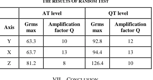
Random vibration test is taken to determine Grms max and amplification factor Q. The results are shown in Table 8.
TABLE8
THE RESULTS OF RANDOM TEST
AT level QT level Axis Grms
max
Amplification factor Q
Grms max
Amplification factor Q
Y 63.3 10 92.8 12
X 63.7 13 94.4 13
Z 81.2 8 126.4 10
VII. CONCLUSION
This paper discussed the structural design and manufactured for 3U cubesat structure using CFRTP/PEEK material. The methods used for verifying the manufactured structure are presented, including finite element analysis and environmental tests. The analysis and test results are also described and evaluated in detail to ensure the survivability of the structure under the launching requirement. Those results proved that CFRTP/PEEK material is very reliable when used as a 3U satellite structure.
Acknowledgments
This research is granted by Ministry of Science and Technology (MOST) in of Vietnam through the funding of FIRST Project (Fostering Innovation through Research, Science and Technology Project) (Financing Agreement number: 08/FIRST/1.a/VNSC); Vietnam National Space Center (VNSC), Vietnam Academy of Science and Technology (VAST) through the Vietnam Space Center Project.
This research is supported by Prof. Okuyama, Department of Applied Science for Integrated System Engineering and Laboratory of Spacecraft Environment Interaction Engineering, Graduate school of Engineering, Kyushu Institute of Technology, Kitakyushu, Japan.
REFERENCES
The heading of the References section must not be numbered. All reference items must be in 8 pt font. Please use Regular and Italic styles to distinguish different fields as shown in the References section. Number the reference items consecutively in square brackets (e.g. [1]).
[1] Cal Poly SLO, CubeSat Design Specification, Rev 13, February 20, 2014.
[2] Japan Aerospace Exploration Agency, User's manual of H-IIA rocket (in Japanese), JERG-4-011A, 2015.
[3] Mitsubishi Heavy Industries, Ltd., User's manual of H-IIA rocket, YET04001, Vol.4, 2015, Japan.
[4] M. J. Casiano, Extracting Damping Ratio from Dynamic Data and Numerical Solutions, NASA TM-2016-218227, 2016.
[5] Duong, B.N, Mashima, Y., Fujii, H., Okuyama, K., The Structural Design Process of Shinen2 Probe from Concept to Launch, 30th International Symposium on Space Technology and Science, Kobe, Japan, July 2015.
[6] Duong, B.N, Okuyama, K., HIBINO, S., Structural Design and Verification of the Shinen2 Probe, 57th JSASS/JSME/JAXA Structures conference, Okayama, Japan, August 2015.
[7] Bui Nam DUONG, Truong Xuan HUNG, Nguyen Duc MANH and
[image:5.612.42.298.188.323.2]