ISSN Online: 2160-0503 ISSN Print: 2160-049X
Detailed Mechanism and Engineering
Applicability of Electrolytic Polymerization Aided
by a Magnetic Field in Natural Rubber by
Mechanical Approach for Sensing (Part 1): The
Effect of Experimental Conditions on Electrolytic
Polymerization
Kunio Shimada
1*, Norihiko Saga
21Department of Symbiotic Systems Sciences, Fukushima University, Fukushima, Japan 2Department of Human System Interaction, Kansai Gakuin University, Hyogo, Japan
Abstract
Ordinary electrolytic polymerization has involved plastic-type polymer solutions. Rubber, especially natural rubber, is one such polymer solution. Rubber has not been focused on until recently due to the fact that electrolytic polymerization has only a very small effect on rubber. However, when we focus on the C=C bonds of natural rubber, the same electrolytic polymerization is applicable to be enlarged on the nat-ural rubber if a magnetic field and a filler are added. With the application of a mag-netic field and a magmag-netic responsive fluid such as magmag-netic compound fluid (MCF), the effect of electrolytic polymerization on NR-latex such as plastic-type polymer so-lutions is enhanced, and the thickness of the vulcanized MCF rubber grows in a short time. The present new method of vulcanization of MCF rubber is effective enough that it is widely used in haptic sensors in various engineering applications. In the present report, as mechanical approach for the sensing, by measuring the tempera-ture under electrolytic polymerization, by investigating the electric and dynamic characteristics, and by observing the magnified appearance of the MCF rubber, we clarified the extrinsic effects of many experimental conditions, including magnetic field strength, applied voltage, the electrodes gap, mass concentration, and the ingre-dients of the MCF. This report is Part 1, to be followed by another sequential report, Part 2, in which other intrinsic effects on the characteristics are dealt with. The expe-rimental conditions used and the results obtained in the present report provide val-uable data that will be useful in the making of MCF rubber.
How to cite this paper: Shimada, K. and Saga, N. (2016) Detailed Mechanism and Engineering Applicability of Electrolytic Polymerization Aided by a Magnetic Field in Natural Rubber by Mechanical Approach for Sensing (Part 1): The Effect of Experi-mental Conditions on Electrolytic Polyme-rization. World Journal of Mechanics, 6, 357-378.
http://dx.doi.org/10.4236/wjm.2016.610026
Received: September 17, 2016 Accepted: October 21, 2016 Published: October 24, 2016
Copyright © 2016 by authors and Scientific Research Publishing Inc. This work is licensed under the Creative Commons Attribution International License (CC BY 4.0).
http://creativecommons.org/licenses/by/4.0/
Keywords
Sensor, Electrolytic Polymerization, Magnetic Field, Magnetic Cluster, Natural Rubber
1. Introduction
The development of conductive polymers has become more common and the principle on which it is based is well-known. Since Heeger, MacDiarmid and Shirakawawa were awarded the Nobel Prize in Chemistry in 2000 [1], the method of electrolytic polymeri-zation has been used to further develop on electrically conductive polymers, not only polyacetylene, which they dealt with, but also polyparaphenylene, polyaniline, polypyr-role, etc. The most conductive polymers have π bonds such as isoprene C=C in the main chain and then become π-conjugated polymers. The π-conjugated system is such an important factor because it produces electrical conductivity. By methods of catalysis such as the Ziegler-Natta method [2] or by doping using I2, AsF5 [3], etc., the carrier
freely moving through the C=C induces electrical conductivity so that the plastic be-comes conductive, although ordinal polymer solutions are insulators.
or-der of 10 nm dispersed in a solvent. Practically, Fe3O4 particles are obtained from the
magnetic fluid (MF), which is compounded with metal powder. The MF is a colloidal suspension with Fe3O4 in a solvent. The Fe3O4 particles have the role of bonding among
the metal particles, and numerous metal and Fe3O4 particles are aggregated in the MCF
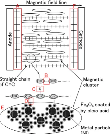
[8]. The magnetic clusters formed by the aggregation take shapes such as prolate sphe-roids, needles, or networks as a result of the application of a magnetic field. Therefore, when natural rubber combined with MCF is electrically polymerized under the applica-tion of a magnetic field, the magnetic cluster is aligned along the direcapplica-tion of the mag-netic field lines in the same direction as the electric field. The polymerized C=C arrays along the same direction as the magnetic clusters. The system was demonstrated in the previous paper, as shown in Figure A1 in the Appendix[7]. At the same time, the C=C bonds are vulcanized by radial polymerization as shown by the letter C in Figure A1. In addition, the vulcanization reaction to radical polymerization occurs as a result of the carboxyl group COOH of the oleic acid coating Fe3O4, and then C=C and Fe3O4 are
bonded as shown by the letter D in Figure A1. The detail investigation of the electro-lytically polymerized MCF rubber by material analysis is interesting and significant, however, this is irrelevant to the main subject. Therefore, we may leave the details and will show them in another report.
The efficacy of the magnetic clusters involved in the MCF at the various engineering applications, for example, damper [9]-[11], polishing [12]-[17], and MCF rubber made of silicon-oil rubber [18]-[21] has been clarified. The properties of their engineering applications changes to be enhanced by the behavior of the magnetic clusters controlled by the applied magnetic field, comparing to those in the case of utilizing ordinary magnetic responsive fluids, for example, MF and magneto-rheological fluid which are called as another name, intelligent fluid.
In addition, it can be utilized as an actuator, and its effectiveness has been shown by utilizing other polymer solutions not containing rubber but that have elasticity [29]- [31]. Thus, it would be useful to make rubber electrolytically polymerized material.
However, previous papers [6] [7] have shown the principle of the new method of electrolytic polymerization that involves with the aid of a magnetic field and an MCF as denoting the applicability of the MCF rubber sensor made by the new method for sensing. Also, the applicability of the enhancement of electrolytic polymerization using a magnetic field to haptic sensor, which is necessary to produce eminent electric and dynamic properties, has been shown through investigating mechanical approach. How-ever, the detailed experimental conditions for the new method of electrolytic polymeri-zation with the aid of a magnetic field and MCF have not been determined. The elec-trical conditions of the applied voltage and electric current, the magnetic field strength, the concentration of particles in the MCF, the electrodes gap, the ingredients of the MCF rubber, and so on are important factors in the experimental conditions. The vul-canization of the MCF rubber varies in correlation with these factors. In the present report, therefore, we clarify the effect of these extrinsic experimental parameters on the new method by investigating electric and dynamic characteristics of the MCF rubber by the same mechanical approach as in the previous research [6][7].
In addition, prior to our clarification of the effect of the experimental parameters in the present report, we also investigate the mechanism of electrolytic polymerization by the new method in greater detail by measuring the temperature under the vulcaniza-tion.
However, there are also other effects of parameters to be seen in the ordinary elec-trolytic polymerization of plastic-type conductive polymer solutions. In addition, the present new method is distinctive in that it uses only a magnetic field without the com-plementary technique of another catalyst or of doping in the electrolytic polymeriza-tion. If the MCF rubber is doped with chemicals, other elements could be devised other engineering applications except for the haptic sensor, for example, Piezo-electric ele-ments, Peltier eleele-ments, a capacitor, a battery, and so on. The experimental condition can be understood to be one of extrinsic effects on the MCF rubber. We can understand that the doping is situated on one of extrinsic effects on the MCF rubber and the intrin-sic effect, for example, Piezo effect is occurred by the doping. Therefore, the intrinintrin-sic effect as well as the extrinsic effect should be investigated. Regarding these topics, a se-quel to the present report, to be referred to as “Part 2”, will follow.
2. New Method
We used the same ingredients in the present MCF rubber liquid as in the previous re-port [7]; these included Ni powder having μm-ordered twig-shaped particles (No. 123 by Yamaishi Co. Ltd. in Japan), water-based MF containing Fe3O4, and NR-latex
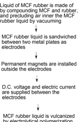
Figure 1. Procedure of making of MCF rubber by electrolytic polymerization.
rubber liquid was poured on one metal plate and sandwiched by another plate. Perma-nent magnets having 15 mm × 10 mm rectangular surface were applied to the inside of the plates form the outer each plate. The applied magnetic field at the position of the MCF rubber liquid was between 130 mT and 490 mT. Voltage and electric current were supplied between the plates, which were held apart with a constant space using a spacer. The applied voltage was between 1.5 V and 9 V. The power was held constant at 16.2 W by adjusting the applied electric current. The electrodes gap was between 0.21 mm and 1 mm. We used plates made of stainless with 35 mm-square surface and 1 mm-thickness and conducted the experiment under the atmospheric conditions of the room over the experiment in the present report.
As in our previous report [7], we investigated the properties of MCF rubber in order to determine whether it could be applied for use in the preceding applications. Many experimental approaches can be considered, for example, dynamic measurement of stress-strain response, electrical measurement of electric current and resistance, and et al. In the present investigation, for the preceding haptic sensing utilizing electric cur-rent or resistance, we deal with electrical experiment.
3. Effect of Parameters on MCF Rubber Vulcanization
atmospheric temperature. On the other hand, the thickness of the MCF rubber without the magnetic field was smaller than that with the magnetic field. Therefore, the applica-tions of the magnetic field and the MCF as filler were sufficient to enhance the rubber thickness.
The changing thicknesses of the MCF rubber can be explained by the fact that the thermal energy converted from the applied electric energy contributes to the vulcaniza-tion. As the electrolytic polymerization is enhanced, C = C bonds have greater thermal energy, and then the vulcanization increases. The temperature of the MCF rubber that had a small electrodes gap in the middle of the vulcanization, data that was not shown in the previous report [7], is very important to know when investigating electrolytic polymerization. Therefore, we measured the temperature using a thermocouple in-serted between the electrodes at the case of 1-mm electrodes gap as shown in Figure A3
in the Appendix.
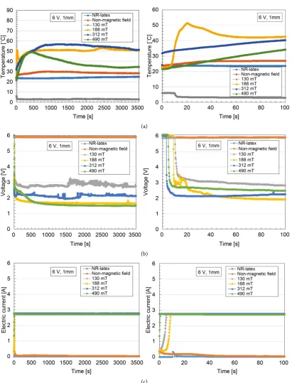
Figure 2 shows the effect of the applied magnetic field on the MCF rubber by show-ing the variation of the temperature as well as the voltage and the electric current of the rubber with differences in the magnetic field strength. The figure on the right shows in detail the initial period of the figure shown on the left side. The applied electric field is 6 V and 2.7 A. The space between the electrodes is 1 mm. On the other hand, the MCF consists of 12 g of Ni, 3 g of water-based MF having 50 wt% of Fe3O4 (M-300, Sigma
Hi-Chemical Co. Ltd., Japan), and 12 g of NR-latex, and the mass concentration of the magnetic and the metal particles is 48.8 wt% in Figure 3 and Figure 4 as well as in
Figure 2. In Figure 2, the magnetic field strength at the position of the MCF rubber liquid between the electrodes is shown. The results of NR-latex rubber, indicated as “NR-latex”, and those of MCF rubber under the application of an electric field without a magnetic field, indicated as “Non-magnetic field”, are also shown for comparison. In the case in which only NR-latex rubber was used, there was no electrolytic polymeriza-tion. When the electricity was first applied, the voltage was held constant at an initial voltage of 6 V, and the electric current was zero because the MCF rubber had not yet vulcanized, and the electrical resistance of liquid MCF rubber is large. Soon after the initiation of electricity, the MCF rubber began to be polymerized electrolytically and thermally, and its thickness increased because the electrolytic polymerization was en-hanced along the magnetic field lines by the magnetic cluster. In the cases with no magnetic field and with low magnetic field strength as shown at 130 mT, because the growth of the electrolytic polymerization was small, the temperature held constant be-fore the electric field was applied. As the magnetic field strength became greater, the growth of the electrolytic polymerization did not increase. There is an optimum mag-netic field strength for the growth of electrolytic polymerization. This is because the magnetic clusters consisting of Fe3O4 and Ni aggregated larger due to the application of
a greater magnetic field at 490 mT, and the electrolytic polymerization of C=C is then suppressed by the magnetic clusters.
(a)
(b)
(c)
Figure 2. Time changes of the temperature, voltage and electric current of MCF rubber influenced by the magnetic field. Because these parameters change under vulcanization by the present new method, the electro-lytic polymerization can be estimated.
[image:7.595.144.556.61.601.2](a) (b)
[image:8.595.241.507.75.271.2](c) (d)
Figure 3. Photographs of spikes in MCF rubber upon the application of the magnetic field: (a) 130 mT; (b) 188 mT; (c) 312 mT; (d) 490 mT. From the phenomena of the spikes, the electrolytic polymerization can be estimated.
Figure 4. Thickness of electrolytically polymerized MCF rubber under the application of the magnetic field from the beginning of the application of the electric field. The vulcanization by the electrolytic polymerization has optimum magnetic field.
Figure 2 before the application of the electric field. A permanent magnet was installed under the plate on which the MCF liquid was put. The MCF used consisted of 12 g of Ni, 3 g of water-based MF having 50 wt% of Fe3O4 (M-300, Sigma Hi-Chemical Co.
Ltd., Japan) and 12 g of NR-latex, which is the same MCF used in Figure 2. Before the application of the electric field, the spikes in the MCF rubber liquid became more solid as the magnetic field strength decreased from the type in Figure 3(d) to the type in
Figure 3(a). The cause of this was as follows. In the case of a high magnetic field strength, Fe3O4 and Ni particles were aggregated rigidly along the magnetic field lines.
[image:8.595.266.477.332.485.2]be-came solid. On the other hand, the thickness of the electrolytically polymerized MCF rubber after the electric field was applied for 30 min is shown in Figure 4, when the electricity was applied at 6 V and 2.7 A with a 1-mm space between the electrodes. The MCF rubber used had the same ratio of ingredients as in Figure 2 and Figure 3. The figure shows that the vulcanized MCF rubber has a maximum thickness. In the case of the large magnetic field, because the rigidly aggregated particles were separated into solid and liquid states, the electrolytic polymerization of C=C was oppressed by the magnetic clusters, and the temperature at the vulcanization and the growth of the elec-trolytically polymerized MCF rubber did not reach their maximums. In the case of the small magnetic field, because the density of the magnetic clusters became small, the temperature at vulcanization and the growth of the electrolytically polymerized MCF rubber did not reach their maximums. Therefore, there is an optimum magnetic field strength at which the temperature at vulcanization and the growth of the electrolytically polymerized MCF rubber reach their maximums, as shown in Figure 2 and Figure 4. Thus, MCF rubber in a moderate mixed solid and liquid state has a relation to the tem-perature and thickness of the vulcanized MCF rubber under electrolytic polymeriza-tion.
Figure 5 shows the effect of the applied voltage on the MCF rubber by showing the variation of the temperature as well as the voltage and the electric current of the rubber with differences in the applied voltage. The applied voltage was changed to hold the electric power constant at 16.2 W by adjusting the electric current. In the figure, the figure on the right shows the initial period from the figure on the left in detail. The ap-plied magnetic field was 188 mT. The space between the electrodes was 1 mm. In cases with a small applied voltage, i.e. 1.5 V, because the electrolytic polymerization was small, the temperature held constant before the electric field was applied. As the applied voltage became larger, the electrolytic polymerization did not become larger. There is an optimum applied voltage in electrolytic polymerization because the electrolytic po-lymerization of C = C is suppressed by the magnetic clusters, as shown in Figure 2.
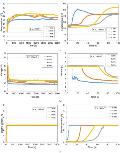
Figure 6 shows the effect of the electrodes gap on the MCF rubber by showing the variation of the temperature as well as the voltage and the electric current of the rubber with differences in the electrodes gap. In the figure, the figure on the right shows the initial period of the figure on the left in detail. The applied electric field was 6 V and 2.7 A. The applied magnetic field was 188 mT. The larger the electrodes gap was, the larger the growth of the electrolytic polymerization became. This occurred because the elec-trolytic polymerization spreads in the direction of the applied electric field. Therefore, if we make thicker MCF rubber, we only have to apply the electric field for a longer time and with a greater electrodes gap.
4. Time Variation of Electric Characteristics
4.1. Experimental Procedure
(a)
(b)
[image:10.595.141.553.65.570.2](c)
Figure 5. Time changes in temperature, voltage, and electric current of MCF rubber influenced by the electric field. The vulcanization by electrolytic polymerization has optimum applied voltage.
(a)
(b)
[image:11.595.143.552.62.585.2](c)
Figure 6. Time changes of temperature, voltage, and electric current of MCF rubber influenced by the elec-trodes gap. The vulcanization by electrolytic polymerization has optimum elecelec-trodes gap.
in a previous report [7]. Because of the effect of the filler used in the MCF rubber on the electrical properties of the rubber in the direction of its thickness, we measured vo-lume resistance, as in the previous report [7].
applica-tion of a normal force to the vulcanized MCF rubber as indicated in the previous report and shown in Figure A4 in the Appendix[7]. For convenience, this experimental pro-cedure is referred to as normal force experimental (NFE).
Secondly, we used another experimental apparatus to measure the electric current, the voltage, or the electrical resistance within the vulcanized MCF rubber with the ap-plication of a shear force as indicated in the previous report and shown in Figure A5 in the Appendix[7]. For convenience, this experimental procedure is referred to as shear force experimental (SFE).
4.2. Results
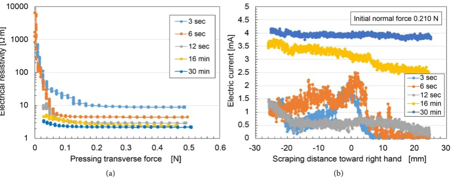
As shown in Figure A2 in the Appendix, the thickness of the vulcanized MCF rubber increased. As for the experiment shown in Figure A2, Figure 7 shows the changes in electrical resistivity at each time of vulcanization: 3 sec, 6 sec, 12 sec, 16 min and 30 min. The normal force changed under shearing motion according to the elasticity of the MCF rubber; the initial normal force before moving is indicated as “Initial normal force”. Regarding SFE, the greater the electric current was, the more sensitive the rub-ber was when utilizing as a sensor with shearing motion. As the vulcanization time was longer, the electrical resistivity was smaller in the case of NFE, and the electric current was larger in the case of SFE. Regarding SFE, at the initial comparative time, the fluctu-ation of the electric current increased. Therefore, as for SFE, the MCF rubber made us-ing short-term vulcanization could be useful in haptic sensors because concave and convex surfaces can be obtained through the variation of the electric current.
By the way, when MCF rubber was made with a 1-mm depth by applying an electric field at 6 V, 2.7 A, and a magnetic field at 188 mT, a duration over which these fields are applied of around 30 min is suitable for the MCF rubber to be vulcanized mod-erately. At an application time of less than 25 min, the vulcanized MCF rubber shows slight fluidity, and at more than 35 min it is vulcanized firmly with cracking in places.
[image:12.595.106.552.487.663.2](a) (b)
When we make MCF rubber with a depth greater than 1 mm, this application time needs to be more than 30 min.
The MCF made with the new method of electrolytic polymerization supplemented by a magnetic field shows superior electrical characteristics to other commercial pres-sure-sensitive electrically conductive rubbers (PSECRs) in both NFE and SFE. This was clarified based on the electric characteristics shown in Figure A6 in the Appendix. The results are for PSECRs made of NR-latex because the present rubber is made of NR- latex.
5. Effect of Parameters on Electric Characteristics
Next, we investigate the effects of the experimental parameters of the magnetic field strength, the concentration of particles of the MCF, the electrodes gap, the ingredients of the MCF rubber, etc., on the electrical characteristics of the vulcanized MCF rubber made by the new method. The figures presented in this section are the results found using the same experimental procedure of NFE and SFE as shown in the last section. They also indicate the results for the MCF rubber under the application of an electric field for 30 min. Regarding SFE, the greater the electric current was, the more sensitive the rubber was when it was utilized as a sensor with shearing motion.
The effect of the applied magnetic field strength is shown in Figure 8. The electricity was applied at 6 V and 2.7 A with a 1-mm space between the electrodes. The MCF used consisted of 12 g of Ni, 3 g of water-based MF having 40 wt% of Fe3O4 (W-40, Taiho
Kozai Co. Ltd., Japan), and 12 g of NR-latex. The mass concentration of the magnetic and metal particles was 48.8 wt%. There was not necessarily a qualitative tendency for the electrical characteristics to increase as the magnetic field strength became larger in both NFE and SFE. As shown in Figure 2, there is an optimum magnetic field strength because of the correlation of the growth of the electrolytic polymerization and the alignment of the magnetic clusters as shown in the previous section.
[image:13.595.105.552.488.662.2](a) (b)
The effect of the mass concentration is shown in Figure 9. The electricity was applied at 6 V and 2.7 A with a 1-mm space between the electrodes. The applied magnetic field was 180 mT. In the figure, the mass concentration of the magnetic and the metal par-ticles was 33.8 wt% with 2.1 g of Ni, 0.525 g of water-based MF having 40 wt% of Fe3O4
(W-40, Taiho Kozai Co. Ltd., Japan), and 4.2 g of NR-latex; 48.8 wt% with 12 g of Ni, 3 g of water-based MF having 40 wt% of Fe3O4 (W-40, Taiho Kozai Co. Ltd., Japan), and
12 g of NR-latex; 69.1 wt% with 12.4 g of Ni, 3.15 g of water-based MF having 40 wt% of Fe3O4 (W-40, Taiho Kozai Co. Ltd., Japan), and 4.2 g of NR-latex. In regard to the
mass concentration, the same qualitative tendency was observed as in the effect of the magnetic field strength as shown in Figure 7, i.e., the tendency for there to be an opti-mum mass concentration, in both NFE and SFE.
The effect of the electrodes gap is shown in Figure 10. The electricity was applied at
[image:14.595.108.551.258.435.2](a) (b)
Figure 9. Effect of mass concentration of particles of MCF on the electrical characteristics of the MCF rubber made by the new method: (a) in the case of NFE; (b) in the case of SFE. It can be realized from electrical characteristics that the vulca-nization by electrolytic polymerization has optimum mass concentration of metal particles.
(a) (b)
[image:14.595.105.552.491.662.2]6 V and 2.7 A. The applied magnetic field was 180 mT. In the figure, the mass concen-tration of the magnetic and the metal particles was 48.8 wt% with 12 g of Ni, 3 g of wa-ter-based MF having 40 wt% of Fe3O4 (W-40, Taiho Kozai Co. Ltd., Japan), and 12 g of
NR-latex. Regarding NFE, as the electrode gap became larger, the electrical resistivity decreased. This occurred because the length of the electrolytic polymerization spread in the direction of the electric field. The tendency was the same as in the case of Figure 6. Regarding SFE, the variation of the electric current was almost the same independent of the electrodes gap. This tendency implies that the mechanism by which the electric current flowed within the MCF rubber in the case of SFE was different from that in the case of NFE. As for NFE, the electric current flowed in the same direction as the aligned C=C and magnetic clusters. As for SFE, the electric current flowed transversely to the direction of the aligned C=C and magnetic clusters. Therefore, the electric current in the former case flowed more easily than in the latter case.
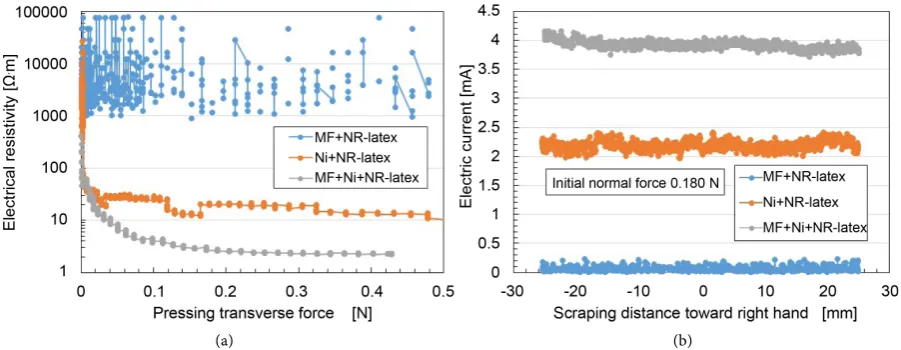
The effect of the ingredients of the MCF rubber is shown in Figure 11. The electrici-ty was applied at 6 V and 2.7 A with a 1-mm space between the electrodes. The applied magnetic field was 180 mT. In the figure, “MF + NR-latex” refers to water-based MF having 1 g of 40 wt% of Fe3O4 (W-40, Taiho Kozai Co. Ltd., Japan) and 5 g of NR-latex,
“Ni + NR-latex” refers to 4 g of Ni and 5 g of NR-latex, and “MF + Ni + NR-latex” re-fers to 1.25 g of water-based MF having 40 wt% of Fe3O4 (W-40, Taiho Kozai Co. Ltd.,
Japan), 5 g of Ni, and 5 g of NR-latex. When the MCF was compounded by just MF, the electrical characteristics were very weak. Therefore, 1 μm-ordered metal particles, such as Ni powder, are very important for the growth of the electrolytic polymerization and the alignment of the magnetic clusters, because magnetic clusters are formed largely owing to the 1 μm-ordered metal particles. In deed the just Ni particles without MF are formed magnetic cluster, but the magnetic cluster size is smaller than formed by Ni and Fe3O4 particles, as clarified by the other report [8]. Therefore, the electrical resistivity
and the electric current in the case involved Ni is located between the case involved MF
[image:15.595.103.554.488.663.2](a) (b)
and the case involved MF and Ni.
Incidentally, although we have not mentioned the atmospheric conditions, the hu-midity and temperature of the atmosphere are also important experimental conditions when making MCF rubber. The experimental conditions have been obtained from many experiments and it was found that humidity between 40% and 50% and a tem-perature between 20˚C and 25˚C within the experimental circumference in the labora-tory were the best for making MCF rubber by the present new method. Outside of these ranges, MCF rubber is vulcanized with slight fluidity or is firm with cracking in places.
6. Concluding Remarks
By focusing on the C=C in natural rubber, NR-latex, we conducted electrolytic polyme-rization aided by the application of a magnetic field and MCF as a filler, and we were able to produce electrolytic polymerization in NR-latex, such as plastic, in a polymer solution. We observed many effects of the enhancement of the electrolytic polymeriza-tion by mechanical approach as follows.
There arean optimum magnetic field strength and optimum applied voltage that can maximize the growth of electrolytic polymerization. These optima occurred due to the correlation of the magnetic clusters consisting of Fe3O4 and Ni which aggregated larger
as a result of the application of the magnetic field and the electrolytic polymerization of C=C bonds. The correlation is related to the moderate mixed states of the solid and liq-uid MCF rubber which can be considered by the phenomena of the MCF liqliq-uid’s spike under the application of a magnetic field before the electrolytic polymerization. Because of the correlation, the large effects of magnetic field strength and the mass concentra-tion of particles in the MCF on the electrical characteristics under normal and shear motions have optimum value.
The larger the electrodes gap was, the larger the growth of the electrolytic polymeri-zation became. This occurred because the length of the electrolytic polymeripolymeri-zation spread in the direction of the electric field. Regarding NFE, as the electrode gap became larger, the electrical resistivity decreased. However, regarding SFE, the fluctuation of the electric current showed almost the same quantitative tendency independently of the magnitude of the electrodes gap, which is different from NFE.
When the MCF was compounded by just MF, the electrical characteristics were very weak. Therefore, the metal particles such as Ni were very important to the growth of the electrolytic polymerization and the alignment of the magnetic clusters.
As for SFE, the MCF rubber made by short-term vulcanization could be useful in haptic sensors because concave and convex surfaces can be obtained by varying the electric current.
The atmospheric conditions, namely the humidity and the temperature of the at-mosphere, are also important experimental conditions in the making of MCF rubber.
Acknowledgements
A part of writing of this paper was made possible largely through grants from JSPS KAKENHI Grant with Number JP 15K05886, and I would like to acknowledge here the generosity of these organizations.
References
[1] Shirakawa, H., Lois, E.J., MacDiarmid, A.G., Chiang, C.K. and Heeger, A.J. (1977) Synthesis of Electrically Conducting Organic Polymers: Halogen Derivatives of Polyacetylene, (CH)x.
Journal of the Chemical Society Chemical Communications, 16, 578-580. http://dx.doi.org/10.1039/c39770000578
[2] Naarmann, H. and Theophilou, N. (1987) New Process for the Production of Metal-Like, Stable Polyacetylene. Synthetic Metals, 22, 1-8.
http://dx.doi.org/10.1016/0379-6779(87)90564-9
[3] Ballard, D.G.H., Courtis, A., Shirley, I.M. and Taylor, S.C. (1983) A Biotech Route to Poly-phenylene. Journal of the Chemical Society Chemical Communications, 954-955. http://dx.doi.org/10.1039/c39830000954
[4] Pojanavaraphan, T., Chirasakulkarun, A., Muksing, N. and Magaraphan, R. (2009) Electro-lytic Admicellar Polymerization of Pyrrole on Natural Rubber/Clay Nanocomposites. Jour-nal of Applied Polymer Science, 112, 1552-1564. http://dx.doi.org/10.1002/app.29312 [5] Fabre, F.I., Aubert, P.H., Alfonsi, S., Vidal, S.F., Sauques, L. and Chevrot, C. (2012)
Elec-tropolymerization of 3,4-Ethylenedioxythiophene with in an Insulating Nitrile Butadiene Rubber Network: Application to Electroreflective Surfaces and Devices. Solar Energy Mate-rials & Solar Cells, 99, 109-115. http://dx.doi.org/10.1016/j.solmat.2011.07.004
[6] Shimada, K. (2015) Study of New Making Technique of MCF Haptic Rubber. Mechanical Engineering Congress, 15, J2220104.
[7] Shimada, K. and Saga, N. (2016) Mechanical Enhancement of Sensitivity in Natural Rubber Using Electrolytic Polymerization Aided by a Magnetic Field and MCF for Application in Haptic Sensors. Sensors, 16, 1521. http://dx.doi.org/10.3390/s16091521
[8] Shimada, K., Miyazaki, T., Shibayama, A. and Fujita, T. (2003) Extraction of Magnetic Clusters Self-Assembled by a Magnetic Field. Smart Materials and Structures, 12, 297-303. http://dx.doi.org/10.1088/0964-1726/12/2/318
[9] Shimada, K., Kanno, H., Ogawa, J., Shuchi, S. and Kamiyama, S. (2003) Development of Non-Sedimentation Type Damper. Trans. Transactions of the Japan Society of Mechanical Engineers B, 69, 2075-2082. http://dx.doi.org/10.1299/kikaib.69.2075
[10] Kanno, H., Shimada, K. and Ogawa, J. (2005) Experimental Investigation of Variable Damping Properties for Viscous Damper Utilizing a Magnetic Responsive Fluid. Transac-tions of the Japan Society of Mechanical Engineers B, 71, 869-876.
http://dx.doi.org/10.1299/kikaib.71.869
[11] Kanno, H., Ogawa, J. and Shimada, K. (2007) MR Fluid Damper Composed of Different Size of Particles. International Journal of Applied Electromagnetics and Mechanics, 25, 109-112.
[12] Wu, Y., Shimada, K., Wong, Y.C. and Kato, M. (2005) An Approach to Surface Finishing Using a Newly Developed Magnetic Polishing Liquid (MPL). International Journal for Manufacturing Science & Technology, 5, 46-54.
Engi-neering Materials, 291-292, 337-342.
http://dx.doi.org/10.4028/www.scientific.net/KEM.291-292.337
[14] Shimada, K., Matuo, Y., Yamamoto, K. and Wu, Y. (2008) A New Float-Polishing Tech-nique with Large Clearance Utilizing Magnetic Compound Fluid. International Journal of Abrasive Technology, 1, 302-315. http://dx.doi.org/10.1504/IJAT.2008.020564
[15] Sato, T., Wu, Y., Lin, W. and Shimada, K. (2009) Study of Three-Dimensional Polishing Using Magnetic Compound Fluid (MCF). Advanced Materials Research, 76-78, 288-293. http://dx.doi.org/10.4028/www.scientific.net/AMR.76-78.288
[16] Wu, Y., Jiao, L., Guo, H., Fujimoto, M. and Shimada, K. (2012) Ultrafine Surface Finishing of Fused Silica Glass Using MCF Magnetic Compound Fluid Wheel. Advanced Materials Research, 565, 3-9. http://dx.doi.org/10.4028/www.scientific.net/AMR.565.3
[17] Wang, Y., Wu, Y., Uuo, H.G., Fujimoto, M., Nomura, M. and Shimada, K. (2015) A New Magnetic Compound Fluid Slurry and Its Performance in Magnetic Field-Assisted Polish-ing of Oxygen-Free Copper. Journal of Applied Physics, 117, Article ID: 17D712.
http://dx.doi.org/10.1063/1.4914058
[18] Ido, Y., Ishida, S. and Shimada, K. (2007) Vibration Response of a Silicon Rubber Mem-brane Containing a Magnetic Compound Fluid Induced by an Impulsive Magnetic Field. International Journal of Applied Electromagnetics and Mechanics, 25, 151-155.
[19] Zheng, Y., Shimada, K. and Ido, Y. (2008) Research on a Haptic Sensor Made Using MCF Conductive Rubber. Journal of Physics-Condensed Matter, 20, Article ID: 204148. http://dx.doi.org/10.1088/0953-8984/20/20/204148
[20] Ido, Y., Yamada, T. and Shimada, K. (2008) Vibration Properties of a Coupled System of a Magnetic Fluid Layer and a Magnetic Rubber Membrane. International Journal of Applied Electromagnetics and Mechanics, 28, 129-134.
[21] Zheng, Y. and Shimada, K. (2008) Study on a Haptic Sensor Using MCF (Magnetic Com-pound Fluid) Electric Conductive Rubber. Journal of Solid Mechanics and Materials Engi-neering, 2, 748-755. http://dx.doi.org/10.1299/jmmp.2.748
[22] Kawasaki, H., Komatsu, T. and Uchiyama, K. (2002) Dexterous Anthropomorphic Robot Hand with Distributed Tactile Sensors: Gifu H and Ⅱ. 1999 IEEE International Conference on Systems, Man, and Cybernetics, 2, 296-303.
http://dx.doi.org/10.1109/tmech.2002.802720
[23] Lee, H.K., Chang, S.I. and Yoon, E. (2009) Dual-Mode Capacitive Proximity Sensor for Robot Application: Implementation of Tactile and Proximity Sensing Capability on a Single Polymer Platform Using Shared Electrodes. IEEE Sensors Journal, 9, 1748-1755.
http://dx.doi.org/10.1109/JSEN.2009.2030660
[24] Kimoto, A., Sugitani, N. and Fujisaki, S. (21010) A Multifunctional Tactile Sensor Based on PVD Films for Identification of Materials. IEEE Sensors Journal, 10, 1508-1513.
http://dx.doi.org/10.1109/JSEN.2010.2044407
[25] Dargahi, J. (2002) An Endoscopic and Robotic Tooth-Like Compliance and Roughness Tactile Sensor. Journal of Mechanical Design, 124, 576-582.
http://dx.doi.org/10.1115/1.1471531
[26] Tanaka, M., Tanaka, Y. and Chonan, S. (2008) Measurement and Evaluation of Tactile Sensations Using a PVDF Sensor. Journal of Intelligent Material Systems and Structures, 19, 35-42. http://dx.doi.org/10.1177/1045389X06072802
[28] Sato, K., Kawakami, N., Kamiyama, K. and Tachi, S. (2010) Finger-Shaped Gelforce: Sensor for Measuring Surface Traction Fields for Robotic Hand. IEEE Transactions on Haptics, 3, 37-47. http://dx.doi.org/10.1109/TOH.2009.47
[29] Hirai, T., Zheng, J. and Watanabe, M. (1999) Solvent-Drag Bending Motion of Polymer Gel Induced by an Electric Field. SPIE Proceedings, 3669, 209-217.
http://dx.doi.org/10.1117/12.349679
[30] Yamane, T., Mukai, H., Asaka, K. and Doi, M. (2005) Electrostress Diffusion Coupling Model for Polyelectrolyte Gels. Macromolecules, 38, 1349-1356.
http://dx.doi.org/10.1021/ma047944j
Appendix
[image:20.595.284.462.196.413.2]The schematic diagram of electrolytic polymerization of the new method was shown in a previous report as shown in Figure A1 [7]. At the cathode, the surface of the MCF rubber becomes rugged due to the tip of the growing vulcanization of the MCF rubber. At the anode, cationic polymerization occurs, and at the cathode anionic polymeriza-tion occurs, as indicated by the A and F labels within Figure A1.
[image:20.595.245.502.458.664.2]Figure A2 shows the changes over time of the thickness of the vulcanized MCF rubber,
Figure A1. Model of electrolytic polymerization and vulcanization of MCF rubber by the present new method [7].
Figure A2. Changes in voltage, electric current, and thickness of MCF rubber over time during the period of vulcanization. The data indicated “NR-latex + MF + Ni, mag.” were shown in the previous report [7].
S
C=C C=C
C=C
C=C C=C
C=C
Magnetic cluster Straight chain
of C=C
Magnetic field line
Fe3O4coated
by oleic acid
Metal particle (Ni)
A F
B
C
as well as the electric current and voltage. The labels “non-mag.” and “NR-latex” indi-cate the cases of electrolytic polymerization without the application of the magnetic field. Electricity was applied at 6 V, 2.7 A, and 188 mT, with a 1.3-mm space between the electrodes. The MCF used consisted of 12 g of Ni, 3 g of water-based MF having 40 wt% of Fe3O4 (W-40, Taiho Kozai Co. Ltd., Japan), and 12 g of NR-latex. The mass
concentration of the magnetic and metal particles was 48.8 wt%.
The position of the thermocouple used to measure the temperature of MCF rubber vulcanizing under electrolytic polymerization is shown in Figure A3. The thermo-couple is inserted between the electrodes when we make the MCF rubber.
[image:21.595.255.493.275.468.2]The experimental apparatus shown in Figure A4 is used to measure the electric cur-rent, voltage, or electrical resistance between the electrodes opposing each other under the application of a normal force to the vulcanized MCF rubber as indicated in the pre-vious report [7]. We use an electric power supply of 10 V and an electrical resistance of
Figure A3. The thermocouple used to measure the temperature of MCF rubber is inserted be-tween the metal plates while the MCF rubber is being made.
Figure A4. Schematic diagram of the experimental apparatus investigating the electrical characteristics in the case of NFE. The diagram at right shows the details around the electrodes section [7].
①Metal plate
①
②Spacer
③Liquid of MCF rubber
Application of a voltage
④Permanent magnet
④
[image:21.595.142.552.512.677.2]1.8 kΩ. The vulcanized MCF rubber is settled between the two electrodes, which are 7-mm squares in shape and are made of stainless steel. The upper electrode is moved and touched to the lower one by an actuator with a moving speed of 10 mm/min.
Another experimental apparatus shown in Figure A5 is used to measure the electric current, voltage, or electrical resistance within the vulcanized MCF rubber as indicated in the previous report [7]. We use an electrical power supply of 10 V and an electrical resis-tance of 1.8 kΩ. Both tips of the solidified MCF rubber are settled between the two elec-trodes of the stainless plate. The MCF rubber is touched to a rubbing material having a surface roughness of Ra= 20.86 μm, Ry= 199.9 μm, Rq = 26.89 μm, and is moved parallel
[image:22.595.144.547.292.442.2]to the material surface by an actuator with a moving speed of 5 mm/s and a sweeping dis-tance of 50 mm. A hard non-electric body with φ 5 mm is interposed between the MCF rubber and the acrylic resin body so that the MCF rubber can be touched exactly.
[image:22.595.98.552.485.688.2]Figure A6 shows the electrical characteristics of the PSECR made of NR-latex, except for those made of silicon oil and CR rubbers as shown in the previous report [7].
Figure A5. Schematic diagram of experimental apparatus investigating the electric characteristics in the case of SFE. The diagram at right shows the details around the electrodes section [7].
(a) (b)
Submit or recommend next manuscript to SCIRP and we will provide best service for you:
Accepting pre-submission inquiries through Email, Facebook, LinkedIn, Twitter, etc. A wide selection of journals (inclusive of 9 subjects, more than 200 journals)
Providing 24-hour high-quality service User-friendly online submission system Fair and swift peer-review system
Efficient typesetting and proofreading procedure
Display of the result of downloads and visits, as well as the number of cited articles Maximum dissemination of your research work