ANALYSIS OF LOW RATE CONVOLUTIONAL CODES ON OPTICAL
INTERLEAVE-DIVISION MULTIPLE-ACCESS SCHEME
S. K. Sriwas
1, M. Shukla
2, R. Asthana
2and J. P. Saini
1 1Bundelkhand Institute of Engineering & Technology, Jhansi, India
2Harcourt Butler Technological Institute, Kanpur, India
E-Mail: [email protected]
ABSTRACT
The efficient bandwidth utilization is one of the key aspects for improving the accomplishment of any optical fiber based communication system. Code-Division Multiple- Assess (CDMA) scheme has been popularly deployed, in optical platform, for attaining the higher spectrum efficiency throughout the globe. However, the entire Optical CDMA (O-CDMA) scheme based communication systems have been victim of increased multiple access interference (MAI) with increment in user count. Recently, Interleave-Division Multiple-Access (IDMA) scheme has attracted the researchers for working on its feasibility with optical communication. From the literature, it has been revealed that IDMA scheme, which employs interleavers as the only means for user separation, mitigates efficiently with MAI and other interferences. In this paper, the performance of Optical Interleave Division Multiple Access (O-IDMA) based system has been evaluated using low rate convolution codes. During the simulation, the combination of coding and spreading operations has been employed for maximizing the coding gain using low rate codes. The simulation results establishes thatwith low rate convolution encoding technique, O-IDMA system contributes significant refinement in system performance in comparison to its counterpart i.e. O-CDMA system.
Keywords: optical IDMA, convolution codes, Viterbi decoding, iterative CBC decoding, interleavers.
INTRODUCTION
For establishment of communication link in wired communication, the optical fiber has been frequently employed for achieving high spectral efficiency with O-CDMA based system. Till now, the CDMA scheme has been the most popular alternative of design engineers due to better bandwidth efficiency than its counterparts including Frequency-Division Multiple-Access (FDMA) and Time-Division Multiple-Multiple-Access (TDMA) schemes. The performance of Optical-CDMA (O-CDMA) scheme is reported to be predominately limited by multiple access interference (MAI) and inter-symbol interference (ISI) in addition to other constraints. The solution of aforesaid constraints may be attained by replacing CDMA scheme with the alternate mechanism familiar as Interleave-Division Multiple-Access (IDMA) scheme, defined by Ping et al., 2006, in which, most of above specified problems do not subsist due to implementation of user-specific interleavers having modest cross-correlation amongst them (Cristeaet al., 2009, Mahadevappaet al., 2002, Ping et al., 2006, and Kusumeet al., 2012).The comparison between CDMA and IDMA schemes have been exhibited in (Kusumeet al., 2012) and deduced that user-specific interleavers may anticipate better orthogonality and emerge least interference between each other in the channel.
The O-IDMAscheme is a recently proposed multiple access technique in optical domain, in which varioususer-specific interleaves are being used to distinguish the user-specific data, during communication process. It uses a low-cost iterative chip-by-chip (CBC) multiuser detection algorithm in which the complexity is independent on the count of users, therefore higher number of users can be supported.
In general, the optical fiber is used as channel between transmitter and receiver for long distance communication with high bandwidth efficiency while channel coding is employed for providing secure and accurate transmission of message signal through a communication channel. In this paper, the performance of Optical Interleave-Division Multiple-Access (O-IDMA) scheme using low rate convolution encoding technique has been presented with random interleaving mechanism in addition to its comparison with its counterpart i.e. O-CDMA scheme based communication systems. The simulations have been performed on MATLAB environment.
O-IDMA SYSTEM MODEL
In proposed optical fiber based communication system, the IDMA scheme has been utilized for achieving high spectral efficiency along with modest receiver complexity and improved performance (Depanget al., 2008, Pupeza, 2006, Shuanget al., 2009, Xinyiet al., 2007, and Yeon, 2007). The IDMA scheme pivots on interleaving as the only means to distinguish the signals from various users and therefore it has been named as IDMA scheme.
The application of IDMA in Optical domain plays a vital role for enhancing the accomplishment in terms of bit error rate (BER). The O-IDMA consist the transmitter, optical channel and receiver. The block diagram of O-IDMA transmitter is introduced in Figure-1,while receiver model for O-IDMA system is introduced in Figure-4.
Transmitter structure of O-IDMA system
(E/O) and combiner block for various activities. The input data sequence dk of user-k is encoded employing convolution channel encoder which is in fact a low rate encoder c, generating a coded sequence ck ≡[ck(1),
….,ck(j),…..,cK(J)]T, where J is the frame length. The elements in ck are referred to as coded bits.Hereconvolutional encoder is utilized with (n=2, l=3, m=2) and the generation of convolutional codes is explained just after this section. Coded sequence ckis
rightly permutated by user-specific interleaver k, which
constructs xk= [xk(1)…..xk(j)…..xk (J)]T data streams. The elements in xkare referred to as 'chips' (Ping, 2005 and Wu,
2006).
The decisive principle of IDMA system is implementation of user-specific interleavers {k} for the
impetus of user separation in terms of respective data streams. Conventionally, it is also supposed that the interleavers are precipitated randomly and separately. The interleavers are utilized to disperse the coded sequences. Therefore the adjacent chips are approximately uncorrelated, which makes chip-by-chip detection process relatively facile and fast with smallest BER (Ping, 2005, Shukla, Srivastava et al., 2010).
Succeeding the user-specific interleaver initiation, electrical to optical converter (E/O) is rightly utilized for accomplishing specific optical pulses. The electric field of mode locked laser can be stated as (Shukla, Gupta M. et al., 2010),
= � ∑ − � ∆
= (1)
Where, k and w are designated as the number of modes and channel spacing between two consecutive modes in the mode locked laser (MLL) system respectively.
Additionally, the output of MLL system is modulated with interleaved data xk(j) which is generally a simple on off keying (OOK) modulation. The transmitted
data can be stated as:
� = � � ∑ − � ∆
= (2)
Where, xk(j) (1,0)
Figure-1.Transmitter structure of O-IDMA system.
Low rate convolutional codes
Convolution codes are represented by three parameters n, l, k. where k represents the number of shift registers used in the encoding part (Hochwald, 1998). Where l represents the encoder’s input. The coded sequence of n bits obtained after encoding not only
depends on the k bit information message but also on the previous information bits that is transmitted (Cox, 1994). In convolution codes decoding is done by using both hard decision method and soft decision method. For constraint length k<5, Viterbi algorithm (Viterbi, 1990) is used and for k>5 MAP algorithm is used (Maiya, 2012). In this system, convolution encoder and decoder are implemented. Convolution encoder having shiftregisters (constraint length) k=2 and k=3 having code rate1/2 and 1/3 is implemented.
Simple convolution encoders are shown in Figure-2 and Figure-3. In Figure-2 constraint length is 2 and adders are 3.The coding rate of this encoder is 1/3because three adders are used in it. In Figure-3 constraint length is 2 and two adders are used in this encoder. Therefore coding rate is 1/2. A bit is shifted into the leftmost stage at each input and the bits previously existing in the shift registers are shifted one position to right. After applying the modulo-2 operation corresponding outputs are obtained. This process is continuing until the arrival of data at the input of encoder. The choice of connection between the shift registers and adders describes the characteristics of code. To describe an encoder, set of "m" connection vectors are required. These vectors have the same dimension as that of k (shift registers). These connections describe which shift register is connected with m adders. A value of "1" in the position demonstrates that particular shift register is connected to the adder and a "0" in given position indicate that no connection exits between the stage and adder.
For encoder shown in Figure-2, we can write the connection vector G and G and G as follows:
G1= [1 0 0] G2= [1 1 0] G3=[1 1 1]
Figure-2. Convolution encoder with coding rate 1/3.
For encoder shown in Figure-3, we can write the connection vector G and G as follows:
Figure-3.Convolution encoder with coding rate 1/2.
The output of encoder produces coded sequence
ck which is applied to an interleaver πk and used for further
processing.
Communication channel of O-IDMA system
Pulse propagation in nonlinear optical fiber can be explained by using nonlinear Schrodinger equation (NLS). A(z,t) is denoted as the slowly varying envelope of an optical pulse propagating through nonlinear optical fiber. NSE can be written as [13],
�, ∂z + β
�,
+ β �, = � �, � �, − � �, (3)
Where,j = √− , t is time, 1and 2are the first and second
derivatives of the propagation constant respectively, z is distance along the fiber, is the attenuation and is the non-linear coefficient (Agrawalet al., 1989,Weideman et al., 1986).
The Nonlinear Schrodinger equation (NLS) describing the pulse propagation A(z,t) in an optical fiber can be written as,
��= � + � � (4)
Which, is the nonlinear partial differential equation, L and N are the linear and nonlinear operators, respectively. The properties influencing the optical system performance are fiber attenuation and dispersion (Sriwas et al., 2016).
By using split step method the pulse propagation can also be expressed as
��= − � − � + |�| � (5)
The linear part can be given in terms of attenuation and dispersion .The attenuation can be written as
Attenuation = � × � (6)
Where, α is the attenuation factor. dz is split-step distance. The dispersion is expressed as,
� = � �+ � + � × � (7)
For single mode fiber intermodal, or modal, dispersion equal to zero (β1 = 0),
= � ×− � (8)
= − � + �
�� �� (9)
Where, c is the velocity of light free space.D2 is
the second order dispersion; D3 is the third order
dispersion.
For long distance communication in optical fiber based system, the non-linear distortion is quite crucial parameter in addition to dispersion mechanism which, in a fiber, causes optical signal pulse to broaden as they travel along a fiber. If these pulses travel sufficiently far distance, they will eventually be bound to overlap with the neighbouring pulses, thereby creating errors in the receiver output. Hence, the signal distortion ultimately becomes responsible for limiting the information carrying capacity of a fiber. The nonlinearities are not significant at low power but dependent on the intensity of the signals.The nonlinear part can be given as
��= �
� �
�� × � (10)
Where,I = |signal|2, n2 is the nonlinear factor, Aeffis the
effective cross-section core area of the fiber.
Receiver model of O-IDMA system
Optical IDMA receiver is shown in Figure-4 which consist the optical to electrical converter (O/E), elementary signal estimator (ESE), de-interleavers (π-1), interleavers (π) and decoders (DEC).
Figure-4. Receiver structure of O-IDMA system.
The role of optical receiver is to convert the optical signal back into electrical form and recover the transmitted data. The main component of optical receiver is a photodetector that converts light into electricity through the photoelectric effect. At the receiver front the avalanche photo detector (APD) is used (Agrawal, 2001).Optical detectors must have a wide bandwidth and sharp response to achieve the high bit-rate which is required by such a system. If the input power Pin launched
at the input end of a fiber of length L, the output optical power Pout is given by (Agrawal, 2001)
� can be written as in dB/km
= − � � ��
� (12)
The Photo-current IP generated bythe detectoris directly proportional to the incident optical power Pinand is given by � = �� (13)
Where, R is the responsivity of the photodetector (in units of A/W). The quantum efficiency η can be expressed in term of responsivity R as � = ℎ � � � =�� / � /ℎ = ℎ (14)
The responsivity in terms of gain and quantum efficiency is � =� �ℎ � (15)
Where, G and η are avalanche gain and the internal quantum efficiency respectively, h is Planck’s constant (6628*10-38J/s), and � is the optical frequency, q is the electron charge (1.6*10-19C). The probability that a specified number of photons are absorbed from an incident optical field by a PIN detector over a chip interval with is given by a Poisson distribution. The average number of absorbed photons overTCis shown as � =��ℎ (16)
Where, � is the photon absorption rate, � is the received laser power. After APD, receiver consists of an elementary signal estimator (ESE) and K, aposteriori probability (APP) decoders (DECs) (Cristeaet al., 2009, Mahadevappa et al., 2002). The outputs of the ESE and DECs are extrinsic log-likelihood ratios (LLRs) about {xk(j)} defined below � � (� ) ≡ � � �� � =+=− (17)
Here, eESE(xk(j)) denotes the extrinsic a posteriori log-likelihood ratios (LLRs) produced by the decoding for user k. The received signal r(j) at the ESE can be stated as, = ℎ � + 8
Where, hk denotes the channel coefficient for user k and n(j) denotes the noise sample. For a particular user k, the equation (18) can be modified as (Ping et al., 2006, Ping, 2005, Mahadevappa et al., 2002). = ℎ � + � (19)
Where, � ≡ − ℎ � = ∑ ′≠ ℎ ′� ′ + (20)
Here, E(·) and Var(·) are the mean and variance functions respectively. The list the CBC detection algorithm as follows (with initialization eDEC(xk(j)) = 0,
k, j). The CBC algorithm (Ping et al., 2006) (� ) = tanh � � (21)�� (� ) = − (� ) (22)
(� ) = ∑ ′≠ ℎ ′ � ′ (23)
�� (� ) = ∑ ′≠ |ℎ ′| �� (� ) + � (24)
� � (� ) = � (ℎ� ) − (� ) (25)
After the APP decoding process, further operations are performed in the DECs for generating the LLRs {eDEC(xk(j)),
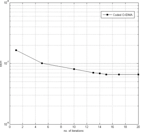
k, j}. Now, again the iterations arerepeated back to (21) for the next iteration, if required. With count of iterations in the receiver, the accuracy of the decoded data increases however, it also increases the mathematical complexity and high power requirement at the receiver side. It has been perceived with numerous simulations that count of 15 iterations in the receiver section, are sufficient for recovery of any user-specific data. The BER vs. number of iteration are shown in figure 3 and explanation is in result and discussion section.
RESULT AND DISCUSSIONS
Figure-5. Uncoded O-CDMA vs. uncoded O-IDMA.
The variation in count of simultaneous users has been opted as parameter of performance during performance comparison to O-IDMA system. The performance evaluation has beencarried out considering the optimal value of parameterswith MATLAB environment. The bit error probability (BER) has been employed as essential tool for estimating the system accomplishment. During the simulation process, the spreading length has beenchosen as 16, and the iterative number is set to be 15. With higher count of iterations in receiver section, the accuracy of user-specific data detection increases however it has been observed from figure 6 that with iteration count more than 15, no significant improvement in BER performance is observed. Further to note that with increment in iteration count, the complexity of receiver also increases.
For simulation purpose, the input data for each user is assumed to be same i.e. 2048 bits. Optical fiber has been operated with 155nm wavelength with maximum bit rate of 1Gbps capability. The transmitted power is chosen to be 1mW, while intensity dependent refractive index
parameter is 20
2.35*10 .The responsivity and efficiency is 0.65 and 0.80 respectively. The input signal at optical fiber is in the form of a Gaussian pulses and ON-OFF keying (OOK) modulation is used for pulse transmission. The interleaving mechanism opted for user separation is taken to be based onrandom interleavers since random interleavers are easy to generate and computational complexities is low at the receiver end.
Figure-6. Count of iterations vs. BER.
The BER performance of O-IDMA system using simultaneous users for convolution codes is demonstrated in Figure-7 with 1/3 coding rate and in Figure-8 with 1/2 coding rate. The simulation results display that, in uncoded O-IDMA, there is zero BER before 40 users while in case of 1/3 convolution coded Optical IDMA system, the error is zero up to 80 users. Moreover, Figure-8displaysconvolution coded Optical IDMA with coding rate 1/2,no error is observed up to 100 users.
[image:5.595.317.545.100.312.2] [image:5.595.316.541.461.671.2]Figure-8. Performance of rate 1/2 coded O-IDMA system.
It is evident from Figure-7 and Figure-8 that the convolution coded O-IDMA schemeproduces better BER as compared to the uncoded Optical IDMA scheme with random interleavers. Therefore convolution coded Optical IDMA system can support the higher number of simultaneous users as compared to the uncoded Optical IDMA scheme.
CONCLUSIONS
In this paper,the essential requirement O-IDMA communication system has been justifiedby comparison of O-IDMA vs. O-CDMA and describes the complete system.In addition to it, the performance of the O-IDMA system using low rate convolution code has also been demonstrated.It has been observed from the simulations that the convolution coded O-IDMA system has better system performance and may support highercount of simultaneous users as compared to uncoded system in comparison to its counterpart i.e. O-CDMA system. The coding rate is an important parameter for convolutional encoder with O-IDMA system and withappropriate coding rate;the performance can further be improved.
REFERENCES
AgrawalG.P.and Olsson A. 1989.Self-phasemodulation and spectral broadening of optical pulses in semiconductor lasers amplifiers. IEEEJournal ofQuantum Electronics. 25(2): 2297-2306. doi: 10.1109/3.42059.
AgrawalG. P. 2001. NonlinearFiberOptics.NewYork, United State of America, Acadmic Press.
Cox R.V. and Sundberg C.E.W. 1994. An Efficient Adaptive Circular Viterbi algorithm for Decoding generalizedTailbiting Convolutional codes. IEEE Transactions on Vehicular Technology. 43(1): 57-68.
CristeaB., Roviras D. and Escrig B. 2009.Turbo receiversfor Interleave division multiple access system.IEEE Transition onCommunications. 57(7): 2090-2097.
doi:10.1109/TCOMM.2009.07.070525.
Dapeng H., Pin Y. and Hoeher P.A. 2008.Analysis anddesign of interleaversets for Interleave-division
multiplexing and
relatedtechniques.InternationalSymposium on Turbo Codes andRelatedTopics, pp. 432-437.doi: 10.1109/TURBOCODING.2008.4658738.
Hochwald B.M. 1998. Source and Channel Coding tradeoff over Gaussian Channel, IEEE International symposium on information theory.pp. 248. doi:10.1109/isit.1998.708853.
Kusume K., Bauch G. and Utschick W. 2012.IDMA vs. CDMA: analysis and comparison of two multiple access schemes. IEEE Transitionon Wireless Communications. 2(1): 78-87.doi: 10.1109/TWC.2011.111211.100954.
MahadevappaR.H. and ProakisJ.G.2002.Mitigating multiple accessinterference andinter symbol interferencein uncoded CDMAsystems withchip level interleaving. IEEETransition on Wireless Communications. 1(4): 781-792. doi:10.1109/ TWC.2002.804163
Maiya S.V., Costello D.J. and Fuja T.E. 2012.Low latency Coding; Convolutional Codes versus LDPC.IEEE Transactions on Communications. 60(5): 1215-1225. doi:10.1109/TCOMM.2012.042712.110189
Ping L. 2005. Interleave Division Multiple Accessand chip by chip Iterative multi user Detection. IEEE journal Radio
Communication. 43(6): S19-S23.doi:
10.1109/MCOM.2005.1452830.
Ping L., Liu L, Wu K and Leung W.K., (2006). Interleave Division Multiple Access. IEEE Transition on Wireless
Communications. 5(4):
938-947.doi:10.1109/TWC.2006.1618943.
Shuang W., Xiang C. and Shidong Z. 2009.AParallel Interleaver Design for IDMA Systems.International Conference on Wireless Communications and Signal Processing, WCSP, Nanjing, China. pp. 1-5. doi: 10.1109/WCSP.2009.5371716
Shukla M., Gupta M, Tiwari S., Sharma P.S, andShukla S. 2010.Optical Interleave-Division Multiple-Access scheme for long distance Optical fiber communication.IEEE International Conference on Computational Intelligence and Computing Research. pp. 1-5.doi: 10.1109/ICCIC.2010.5705771.
Allocation Algorithm. International Journal of Electronics and Telecommunication and Instrumentation Engineering. 2, pp. 15-25.
Sriwas S.K., Shukla M., Asthana R. and Saini J.P. 2016.Fix the nonlinear effect and dispersion in optical interleave division multiple access system for long distance. Indian Journal of science and technology. 9(35): 1-8.
Viterbi A.J. 1990. Very low rate convolutional codes for maximum theoretical performance of spread-spectrum multiple-access channels. IEEE journal of selected areas in communications. 8(4): 641-649.
Weideman J.A.C. and Herbst B.M. 1986. Split-step methods for the solution of the nonlinear schrodinger equation. SIAM J Numer Anal. 23, pp. 485-507. doi: 10.1137/0723033.
Wu H., Ping L. and Perotti A. 2006. User-specific chip level interleaver design for IDMASystem, IEEE Electronics Letters. 42(4): 41-43. doi: 10.1049/el:20063770.
Xinyi X., Quipping Z., Liang Z., WeibingW. andKegang L. 2007.The Modelof EvolutionaryInterleavers for IDMACommunicationSystem. InternationalConference, pp:751- 754.doi:10.1109/WICOM.2007.194