I
i
I
,
;
I
~~~~~""N~~.\':~$~~~1'~~ll:~~~~~ 'rob"~~"~~~{..7.'"C·'~~1·'" ·.tJl!!rj\£.:t~:~.W~~·iN~"YlWl.~.;;n~~:~<tU~~M~~.. i";~-w.:_1i~~"'~~i.~~~~l~,·I~'
!i:. ';.
~
FINAL REPORT
I
iJ
STUDY OF ASSOCIATIVE PROCESSING
I
FOR
I
~.~
~
INTELLIGENCE APPLICATIONS
I
I
pm
:,' .. ,', ,.
~tfl~~·~~:I~V~t.~~~~l1!r~-t~;':'~~.·"!r,~~~~~~~;tl~~j;::ii:5:;;~~~~~~h';-"73"'~.iiA.~!-d . . ' _ ~~"J.~1J1i1~ .... ~ ... ,'t¥'ti.»'"'i!.u~4040.~(~-«·~~:~A~3"'~.~. cit.~~N-, •.• • .... "'~':D'~:t!~'_>",~. :$"'.~,~~ .~ .•
I
1~ ~$,
I
Volume
I -
Basic Report
II
~~
I
i
~
I
Contract XG-4124162-7009)75R
~
~~ ~
,:?A,r.;
ii
I.~
t~
-I
GER·16227
AUGUST 1975
I
CODE IDENT NO. 25500
GOODYEAR AEROSPACE
CORPORATION
AKRON, OHIO 44315
STUDY OF ASSOCIATIVE PROCESSING
FOR
INTELLIGENCE APPLICATIONS
FINAL REPORT, CONTRACT XG-4124{62-7009)75R
VOLUME I - BASIC REPORT
GOODYEAR AEROSPACE CORPORATION
GER-16227
FOREWORD
This final technical report records the efforts and the results
achieved on the study of associative processing for intelligence
applications conducted by Goodyear Aerospace Corporation (GAC) ,
Akron, Ohio. This report entitled, Study of Associative Processing
for Intelligence Applications, is published in three volumes:
Volume I - Basic Report (includes Appendix A), Volume II -
Applica-tion Analysis and ValidaApplica-tion (includes Appendices B through 0), and
Volume III - Error Correction Application Analysis. (Classified).
The study was conducted for the U. S. Government under
Contract XG-4l24 (62-7009)75R. The study covers the period from
11 November 1975 to 11 August 1975. The customer project monitor is
Mr. Malcom Tanigawa. The major contributors to this study were
D. L. Rohrbacher (project engineer), A. E. Hale and R. G. Gall.
SUbstantial contributions were also made by F. G. Carty, R.
o.
Faiss,M. Hansburg and R. W. Messner.
GOODVEAR AEROSPACE
CORPORATION ,
GER-16227
TABLE OF CONTENTS
SECTION Title
I EXECUTIVE SUMMARy . . . . 1
. 1. PROGRAM DESCRIPTION... . . . . . . . . . . . . 1
a. Purpose... I, b. Approach . . . . 1
2. SUMMARY OF RESULTS AND CONCLUSIONS... 2
3 . RECOMMENDATIONS .. 0. • • • • • • • . . . • . • • • • • • • • • • • • 7
II TECHNICAL SyNOPSIS . . . . 9
1. INTRODUCTION. . . . . . . . . . . . . . . . . . . . . . . . . . . . • • 9
2. APPLICATION ANALySIS... 13
a. Image Processing... 13
(1) General... 13
(2) Frequency Domain Filtering... -16
(3) Convolution... 19
(4) Edge Detection... 21
(5) First Differences... -23
(6) Magnification . . . ~... 25
(7) Statistics... 27
(8) Image Averaging... 29
b. Text Search... 33
c. Solution of Linear Systems... 37
d. Matrix Inversion... . . 43
GOODYEAR AEROSPACE CORPORATION
GER-16227
TABLE OF CONTENTS (Cont'd)
SECTION Title Page
f. Antenna Simulation . . . . 51
9.. Error Correction . . . ' . . . . . 57
3. VAJ..,IDATION.. . . • . . . . 58
a. Requirements... 58
b. Validation Problem Description... 59
c. Approach. . . . . ... . . . . 59
d.' R e s u l t s . . . 62
APPENDIX A - STARAN SYSTEM DESCRIPTION
-iv-FIGURE
1
2
3
4
5
6
7
8
9
10
11'
12
13
14
GOODYEAR AEROSPACE CORPORATION
GER-16227
LIST OF ILLUSTRATIONS
Title
Image Averaging Process for Validation . . . .
STARAN Comparison with Conventional Computer .. .
STARAN System Configurations . . . .
,Image Averaging Problem Description . . . .
Simplified Flowchart for Image Averaging . . . .
Simplified Search Routine . . . ' . . . . .
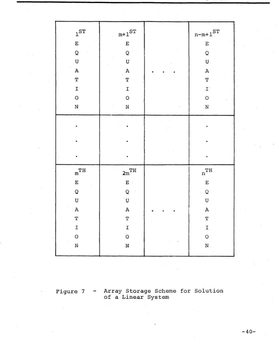
Array Storage Scheme for Solution of a Linear Sys tern . • . . . • • . . • . . • . . .
Operation Counts for Solution of a Linear System
Antenna Simulation Solution Approach . . . .
Validation Problem Description . . . .
Inpu t Imagery . . . . • . . . STARAN E&T Facility Configuration . . . .
Top L~ve1 Flow chart - IAVG • . . . • . .
Image Averaging Process, for Validation - STARAN
vs Sequential Machine . . . • . . .
6
10
12
30
32
35
40
41
54
60
61
63
64
GOODVEAR AEROSPACE CORPORATION
GER-16227
LIST OF TABLES
TABLE Title
I Selected Problems . . . . 3
II Performance Results and Comparisons Summary . • . . . . 4
III Text Search Timing . . . • . . . 36
IV Execution Times for Solution of a Linear System .. 42
V Arithmetic Operation Counts for Matrix Inversion on a Sequential Computer... 45
VI STARAN Operation Count . . . • . . . . • . • . . . • . . . . 47
VII Execution Times for Matrix Inversion . . . . 48
VIII MVP Timing Summary . . . , . . . • . . . 52
IX Antenna Simulation Timing Summary and Comparison. 56 X Detailed STARAN Timing for Validation Program (IA VG) . • • . . . • • • . . . • . . . • • . . . . • • • . . . • . • . • . . . 67
XI Validation Program Statistics . . . • . • . . . • . . . . 68
-vi-GOODYEAR AEROSPACE COAPOA ATION
GER-16227
SECTION I - EXECUTIVE SUMMARY
1. PROGRAM DESCRIPTION
a. Purpose
This study was initiated to investigate and validate the
applica-bility of the STARAN* associative processor (AP) to a variety of
intelligence data processing applications. The goal of this program
is· to provide a solid base for making judgements concerning the
potential benefit that can be obtained through the use of
associa-tive processing.
b. Approach
The study was performed in three phases:
1) application survey
2) detailed analysis
3) validation
The application survey (Phase 1) consisted of the examination of
a variety of intelligence problems to determine their general suitabilitl
for parallel processing. Several of the most promising problems were
to be selected for detailed analysis (Phase 2).. Actually, nearly all
the problems surveyed were judged to be amenable to parallel processing.
Consequently, detailed analysis was performed on 13 problems during the
Phase 2 effort. Finally, one of the problems which was analyzed in
detail was selected for validation (Phase 3). The validation phase
consisted of actually programming the selected problem and executing
i t on the STARAN array processor in the STARAN Evaluation and Training
Facility at Goodyear Aerospace Corporation (GAC) in Akron, Ohio. The
actual programming and execution of the validation problem not only
GOODYEAR AEROSPACE CORPORATION
GER-16227
provided a measured execution time, but also provided additional
statistics which can be directly related to the cost of programming
the STARAN array processor. Since most of the application problems
considered in this study are currently being run on the sequential
machines in the customer computer facility, measured sequential
machine times were supplied by the customer for most of the problems
considered. These measured sequential machine times are included in
this report for comparison with the STARAN approach.
The problems that were selected for analysis, during the Phase 2
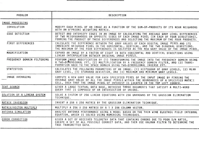
effort, are listed and briefly described in Table I. For each problem,
several variations of system configuration for STARAN were assumed
and performance was analyzed for each variation. Image averaging was
the problem selected for the Phase 3 validation effort. This problem
was also programmed for execution on the IBM 360/195 and 360/65
sequential machines by customer agency personnel. This programming
effort was oriented toward maximization of performance (i.e.,
mini-zation of run time) in order to insure an equitable comparison with
the performance of the corresponding GAC STARAN program.
2. SUMMARY OF RESULTS AND CONCLUSIONS
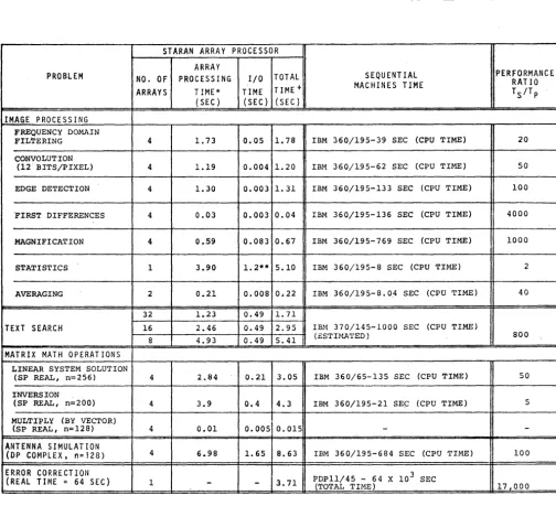
The results of the performance analysis (Phase 2 of the study is
summarized in Table II. This table shows the solution time estimates
for the STARAN implementation of all the problems considered. For
comparison, solution times for sequential-machine implementation of
each of the problems are included. With two exceptions, all the
sequential machine times are measured times supplied by the customer
agency. In the two cases where measured sequential-machine times
were not available from the customer agency, estimates were supplied
by GAC. In most cases, the measured solution times were provid~d for
-2-PROBLEM
IMAGE PROCESSING CONVOLUTION
EDGE DETECTION
FIRST DIFFERENCES
MAGNIFICATION
FREQUENCY DOMAIN FILTERING
STATISTICS
IMAGE AVERAGING
TEXT SEARCH
SOLUTION OF A LINEAR SYSTEM
MATRIX INVERSION
MATRIX/VECTOR MULTIPLY ANTENNA SIMULATION
ERROR CORRECTION
TABLE I - SELECTED PROBLEMS
.
. DESCRIPTION
MODIFY EACH PIXEL OF AN IMAGE AS A FUNCTION OF THE SUM-Of-PRODUCTS Of ITS NEAR NEIGHBORS WITH AN A'PRIORI WEIGHTING MATRIX.
DETECT AND INTE~SIFY EDGES IN AN IMAGE BY CALCULATING THE AVERAGE GRAY LEVEL DIFFERENCES Of TWO NEIGHBORHOODS ON OPPOSITE SIDES OF EACH IMAGE PIXEL (IN EACH OF FOUR DIRECTIONS), FORMING THE PRODUCT Of THESE DIFFERENCES AND SELECTING THE MAXIMUM Of THE FOUR PRODUCTS. CALCULATE THE DIFFERENCE BETWEEN THE GRAY VALUES OF EACH DIGITAL IMAGE PIXEL AND ITS IMMEDIATE NEIGHBOR PIXEL IN THE HORIZONTAL, VERTICAL, AND THE TWO DIAGONAL DIRECTIONS. THE MAXIMUM OF THE FOUR DIFFERENCES IS SELECTED AS THE NEW GRAY VALUE OF THE IMAGE PIXEL. EXPAND AN IMAGE BY A FACTOR OF EIGHT IN BOTH HORIZONTAL A~D VERTICAL DIRECTIONS USING LINEAR INTERPOLATION BETWEEN ORIGINAL IMAGE fIXELS.
PERFORM ~MAGE MODIFICATION BY (1) TRANSFORMING THE IMAGE INTO THE FREQUENCY DOMAIN USING A TWO-DI ENSIONAL FFT, (2) MULTIPLICATION BY A FREQUENCY DOMAIN FILTER, AND (3) TRANS-FORMATION BACK TO THE SPACE DOMAIN USING TWO-DIMENSIONAL INVERSE fFT.
CALCULATES THE FOLLOWING ~ARAMETERS OF AN IMAGE: (1) HISTOGRAM OF GRAY LEVELS, (2) MEAN GRAY LEVEL, (3) STANDARD DEVIATION) AND (4) MAXIMUM AND MINIMUM GRAY LEVELS.
COMPUTE A NEW GRAY VALUE FOR EACH SPECIFIED PIXEL OF THE INPUT IMAGE BY FINDING THE AVERAGE GRAY VALUE OF ALL THE IMAGE PIXELS WITHIN THE BOUNDARIES OF A SPECIFIED MATR:~
CELL, SUCH THAT THE IMAGE PIXEL OF INTEREST IS LOCATED IN THE TOP LEFT CORNER. GIVEN
A
LARGE TEXTUAL DATA BASE, RETRIEVE THOSE DOCUMENTS THAT SATISFY A MULTI-WORD QUERY THAT IS COMPOSED OF AN INTERSECTION OF UNIONS.SOLVE A SYSTEM OF 256 LINEAR EQUATIONS WITH 256 UNKNOWNS BY THE GAUSSIAN ELIMINATION TECHNIQUE.
INVERT A 256 X 256 MATRIX BY THE GAUSSIAN ELIMINATION TECHNIQUE.
MULTIPLY A 256 X 256 MATRIX BY A 1 X 256 COLUMN VECTOR.
ANALYZE ANTENNA PERFORMANCE USING A MODEL BASED ON THE THIN WIRE ELECTRIC FIELD INTEGRAL EQUATION, WHICH IS SOLVED USING NUMERICAL TECHNIQUES.
GIVEN A SET OF RECEIVED TELEMETRY DATA THAT CONTAINS ERRORS DUE TO POOR SIN RATIO,
CREATE A SET OF ALL POSSIBLE CORRECT DATA, AND THEN USE KALMAN FILTER TO DETERMINE THE
TRUE TRANSMITTED DATA. G'l
[image:10.796.54.736.98.579.2]GOODYEAR AEROSPACE
CORPORATION
TABLE II - PERFORMANCE RESULTS AND COMPARISONS SUMMARY
STARAN ARRAY PROCESSOR ARRAY
PROBLEM NO. OF PROCESSING I/O TOTAL SEQUENTIAL PERFORMANCE
TIME + MACHINES TIME RATIO
ARRAYS TIME* TIME T SiT P
(SEC) (SEC ) (SEC )
IMAGE PROCESSING FREQUENCY DOMAIN
FILTERING 4 1. 73 0.05 1. 78 IBM 360/195-39 SEC (CPU TIME) 20
CONVOLUTION
(12 BITS/PIXEL) 4 1.19 0.004 1. 20 IBM 360/195-62 SEC (CPU TIME) 50
EDGE DETECTION 4 1.30 0.003 1. 31 IBM 360/195-133 SEC (CPU TIME) 100
'FIRST DIFFERENCES 4 0.03 0.003 0.04 IBM 360/195-136 SEC (CPU TIME) 4000
MAGNIFICATION 4 0.59 0.083 0.67 IBM 360/195-769 SEC (CPU TIME) 1000
STATISTICS 1 3.90 1. 2** 5.10 IBM 360/195-8 SEC (CPU TIME) 2
AVERAGING 2 0.21 0.008 0.22 IBM 360/195-8.0~ SEC (CPU TIME) 40
32 1.23 0.49 1. 71
TEXT SEARCH 16 2.46 0.49 2.95 IBM 370/145-1000 SEC (CPU TIME)
8 4.93 0.49 5.41 (ESTlMA'l'ED) 800
MATRIX MATH OPERATIONS LINEAR SYSTEM SOLUTION
(SP REAL, n::::256) 4 2.84 0.21 3.05 IBM 360/65-135 SEC (CPU TIME) 50
INVERSION
(SP REAL, n::::200) 4 3.9 0.4 4.3 IBM 360/195-21 SE<:; (CPU TIME) 5
MULTIPLY (BY VECTOR)
(SP REAL, n::::128) 4 0.01 0.005 0.015 -
-ANTENNA SIMULATION
(DP COMPLEX. n=128) 4 6.98 1. 65 8.63 IBM 360/195-684 SEC (CPU TIME) 100
ERROR CORRECTION
103
(REAL TIME = 64 SEC) 1
-
-
3.71 PDP11/45 -(TOTAL TIME) 64 X SEC 17,000GENERAL NOTES; 1. FOR ALL IMAGE PROBLEMS, IMAGE SIZE:::: 512 X 512 PIXELS
2. FOR ALL IMAGE PROBLEMS, 8 BITS/PIXEL UNLESS OTHERWISE NOTED.
3. ALL SEQUENTIAL MACHINE TIMES ARE MEASURED VALUES UNLESS OTHERWISE NOTED.
4. ALL STARAN I/O TIMES BASED ON FAST INTERFACE (EXTENDED MEMORY) UNLESS OTHERWISE
NOTED. •
FOOTNOTES:
5. 25% OVERHEAD TIME INCLUDED IN ALL INDICATED STARAN TIMES
6. TS = SEQUENTIAL SOLUTION TIME
7. Tp = PARALLEL (STARAN) ARRAY PROCESSING SOLUTION 'l'IME
* COMPARE WITH SEQUENTIAL MACHINE CPU TIMES
+ C0l1PARE WITH SEQUENTIAL MACHINE TOTAL TIMES
** CONVENTIONAL DISC I/O
SP = SINGLE PRECISION
[image:11.620.70.574.116.575.2]GOODYEAR AEROSPACE COAPORATION
GER-16227
both the IBM 360/65 and the IBM 360/195. However, only the fastest
sequential machine times available from the customer are included
in Table II. The times for the slower sequential machines are
reported in the individual problem descriptions found in Section II,
TECHNICAL SYNOPSIS. With few exceptions, STARAN provided dramatic
performance increases over the fastest sequential machine, usually
the IBM 360/195. Such dramatic improvements over the powerful
360/195 might naturally raise questions concerning the validity of
the STARAN timing estimates~ This is basic reason for the validation
phase of the study. For validation, one of the problems considered
(image averaging) was actually programmed and executed on the STARAN
at GAC. The very same problem was programmed by the customer agency
and executed on the sequential IBM 360/195 ( and 360/65) computer at
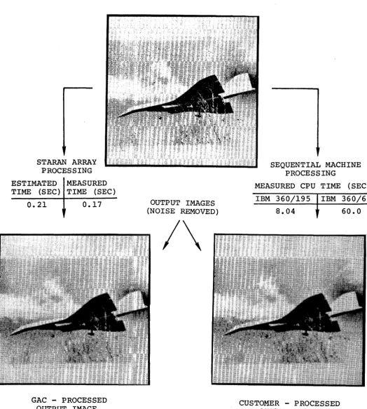
their facility. The image averaging process and results for
valida-tion are shown in Figure 1. Execution time was measured for both
systems. The results showed the STARAN provided a performance
improvement over the IBM 360/195 by a factor of 40. In addition,
the measured STARAN time was about 25 percent faster than the
esti-mated STARAN time. This directly validates the performance estimate
for the image averaging problem, and by implication validates the
performance estimates for all problems considered since the same
basic estimating techniques were used throughout.
The image averaging process is shown also in photographic form
in Figure 1. The same image with noise added was provided as an input
both to the STARAN process and the customers sequential process.
Photographs of the respective outputs are also shown. Note that the
noise was removed, but contrast was reduced somewhat in the process. The contrast could be restored by additional processing, however, this
was beyond the scope of the contract.
STARAN ARRAY PROCESSING
ESTIMATED MEASURED
TIME (SEC) TIME (SEC)
0.21 0.17
GAC - PROCESSED OUTPUT IMAGE
NOISEY INPUT IMAGE
OUTPUT IMAGES (NOISE REMOVED)
/\
GOODVEAR AEROSPACE CORPORATION
GER-16227
SEQUENTIAL MACHINE PROCES'SING
MEASURED CPU TIME (SEC)
IBM 360/195 IBM 360/65
8.04
CUSTOMER - PROCESSED OUTPUT IMAGE
60.0
Figure 1 - Image Averaging Process for Validation
-STARAN vs Sequential Machines
[image:13.615.61.585.98.681.2]-6-GOODVEAR AEROSPACE
CORPORATION
GER-l6227
more complex than for a sequential machine. There are others who
believe programming for a parallel machine like STARAN is not more
difficult', just an exciting new way of thinking. This idea is
re-inforced by the results of the validation phase of this study.
APPLE (~ssociative ~rocessor ~rogramming ~anguag~) was used to
pro-gram STARAN for the validation problem. Programming rate is one
measure of programming complexity (or simplicity). The GAC programmer
achieved a rate of about 9 instructions per hour for just the STARAN
coding process. If the total programming effort (i.e., system
analysis, coding, debugging and documentation) is used to compute
the rate, the result is about 4 instructions per hour. Note that
the programming rates discussed above are rates for only one isolated
problem. However, they are considerably higher than the programming
rates generally encountered in industry for assembly language
program-ming for sequential machines.
3. RECOMMENDATIONS
The ultimate question must be answered is; will the
integra-tion of STARAN into the customer computer facility increase the
cost-effectiveness of that facility? This study provides strong
indications that the performance (a major factor of effectiveness)
of the customer computer facility can be greatly improved by the
addition of a STARANarray processor. The scope of this study,
however, is not sufficient to provide all the necessary information
to answer the total question. Therefore, this contractor recommends
that a direct follow-on effort be carried out to further quantify the
effectiveness as well as the cost factors involved in the addition of
a STARAN array processor to the customer's computer facility. The
items listed below comprise the recommended follow-on effort and, in
general, should be undertaken in the order indicated:
1) Analyze additional application problems and problem
GOODVEAR AEROSPACE CORPORATION
GER-l6227
2) Analyze more aspects, and in more depth, of, some of
the more complex problems already. considered in the
current study, specifically:
(a) Error Correction
(b) Linear Programming package
. 3) Validate additional problems on STARAN
(a) Locally, by GAC programmers
- Reco.mmended problem: Error Correction
(b) Remote Terminal by customer agency programmers
- Recommended problem: Linear Programming
package
4) STARAN hardware configuration/integration/cost study
to determine the optimum methods for integrating STARAN
into the customer's ·facili ty, the recommended STARAN
hardware options and the associated costs.
5) STARAN software integration/cost study to determine the
optimum manner for integrating STARAN software into the
customer's facility' and the associated costs.
-8-GOODYEAR AEROSPACE CORPORATION
GER-16227
SECTION II - TECHNICAL SYNOPSIS
1. INTRODUCTION
This study is primarily dedicated to the investigation of the
applicability of the STARAN array processor to the solution of a
group of data processing and computational problems typical of
those currently being run at the customer's computer facility.
In order to understand the analyses in the items to follow, the reader should have a basic understanding of the STARAN system
organization and how i t differs with conventional digital computer organizations.
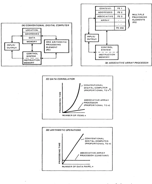
A conventional computer has one central arithmetic PE (Processing
Element) (see Figure 2A). It can perform only one arithmetic
opera-tion - say add or multiply - on only one data pair at a time.
STARAN has an array of PEls, one for each word contained in
memory (see Figure 2B). Each PE operates serially by bit on data
in the memory word to which i t is attached. The PEls simultaneously
ex~cute the instructions designated by the control unit. Therefore, in one instruction execution, the data in all or in selected words
of memory are processed simultaneously by the PEls at each word.
A conventional computer has a location-addressed memory
(Figure 2A). For each input item, i t must search all contents
of its data file one at a time until i t finds the data i t needs,
or engage in complex software routines for storage or retrieval.
Although file structures and programming techniques have lessened
retrieval problems in the conventional processor, these techniques
· GOODVEAR AEROSPACE
CONTENT-ADDRESSED ASSOCIATIVE
ARRAY
PE 1 PE 2
PE 3
CORPORATION GER-16227 MUL TIPLE PROCESSING ELEMENTS (PE)
(A) CONVENTIONAL DIGITAL COMPUTER
LOCATION-ADDRESSED DATA MEMORY CONTROL SYSTEM
ONE ARITHMETIC PROCESSING ELEMENT (PEl
PE 256
,
['NPUTI
OUTPUT1
CONTROL SYSTEM
~
t
-INSTRUCTION
L - -_ _ -4-0 _ _ _ - I < I I I I - - - J MEMORY INSTRUCTION
MEMORY
Figure 2.
(8) ASSOCIA TlVE ARRAY PROCESSOR
(C) DATA CORRELAnON
w ~ i= C) z Cii (/) w U o a: a.. _' CONVENTIONAL DIGITAL COMPUTER (PROPORTIONAL TO n2)
ASSOCIATIVE ARRAY
NUMBER OF ITEMS n
(D) ARITHMETIC OPERATIONS
w ~ i= C) z (/) (/) W U o a: a.. __ CONVENTIONAL DIGITAL COMPUTER (PROPORTIONAL TO n)
ASSOCIATIVE ARRAY / PROCESSOR (CONSTANT)
NUMBER OF DATA PAIRS, n
STARAN Comparison with Conventional Computer
[image:17.615.62.569.88.701.2]-10-GOODVEAR AEROSPAC~
CORPORATION
GER-16227
STARAN has a content-addressed (associative) memory. For each
input data item, i t can search all contents of its data file and identify all elements that meet the search criteria in a single
memory access.
In a conventional computer, all processing and input/output
(I/O) operations treat data in the word direction only.
In STARAN, I/O operations are in the word direction or, in
some cases, in the bit direction; assqciative processing
opera-tions are in the bit direction. To accommodate accesses to
either a word-slice or a bit-slice, each STARAN associative array
module is provided with a multi-dimensional access (MDA) capability.
Either a bit slice (bit n of any or all words) or an entire
word-slice is available to the PE's or I/O channels.
For basic data correlation (see Figure 2C) a conventional
computer, matching "nil input items with "nil items in memory,
approaches a data-correlation (search) time proportional to n2.
STARAN compares each input item with all items in memory
simultane-ously; hence, the data-correlation time is proportional to the
number of inputs and is independent of the number of data items in
memory.
For Arithmetic Operations (see Figure 2D) with a conventional
computer, the arithmetic operation time is proportiona.l to the
number of data pairs being processed. Because STARAN performs the
same arithmetic operations on all data pairs simultaneously, the
processing time is not affected by the number of data pairs being
processed.
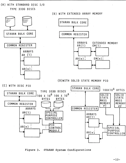
Four different STARAN system configurations were assumed in
the study, depending upon the characteristics of each particular
(A) WITH STANDARD DJSC I/O
TYPE
3330DISCS
GOODYEAR AEROSPACE CORPORATION
GER-16227
(B) WITH EXTENDED ARRAY MEMORY
---. ....
-
---
-STARAN BULK CORE
COMMON REGISTER
ARRAYS
AR
Cl)
AR(n) :
(C) WITH DISC PIO
STARAN BULK CORE·
I
COMMON REG I STE RI
jARRAYS
EXTENDED M
EMORY
A R
(1) .EM
(1 )r---.
~.
.
AR(n) :
EM(n):
~ ~
·(D)WITH SOLID STATE MEMORY PIO
TYPE
3330DISCS
____ S_T_A_RA_N_B-U-L _K _C_O_R_E ...
1 00X
1 0 6 . 1 00X
1 0 6/STARAN BULK CORE
lOOX10
6BYT~S
EAC
SOLID
STATE
MASS
MEMORY
SOLID
STATE
MASS
COMMON REGISTER
ARRAYS·
AR
(1 )AR(n)
BYTES
BYTES
~
SPECIAL
,PURPOSE
CONTROLLER
---1p 10
CONTROl'
MOD.ULE
-rCOMMON RESISTER)
ARRAYS
AR (1 )
#1
.MEMORY -
#2~
I---,~IL SPE'CIA~
I
A R ( n ).
4
: PURPOSE
[image:19.612.43.578.69.760.2]W
CONTROLLERGOODVEAR AEROSPACE
CORPORATION
GER-l6227
were analyzed assuming each of the two system configurations
shown in Figure 3A and 3B. Only the system configuration of
Figure 3B was assumed for the matrix problems, the antenna
simula-tion problem and the error correcsimula-tion problem. This configuration
provides the medium storage capacity and high bandwidth data
transfer necessary because of the large amount of data movement
associated with these problems. Each of the two system
configura-tions shown in Figure 3C and 3D were assumed for the text search
problem, because of the need for very large storage and high
band-width data transfer.
Item 2 to follow in this section provides an abbreviated
descrip-tion of each of the applicadescrip-tion problems considered this study,
along with the general approach for solution by STARAN and the
resulting STARAN performance. Item 3 provides a summary description
of the validation effort, which includes the programming and debugging
of the image averaging problem along with the measured results.
For those readers who are interested in more detail, an
in-depth description of each of the problem solutions as well as the
validation effort, is provided in Volume II.
2. APPLICATION ANALYSIS
a. Image Processing
(1) General
This item contains a description of the application of
STARAN to the general field of image processing. The problems
considered include:
Frequency Domain Filtering
Convolution
First Differences
Magnification
Statistics
GOODVEAR AEROSPACE COAPOA"TION
GER-16227
Basically, the processing to be performed involves arithmetic manipulation of data contained in digital imagery in order to
accomplish a particular form of image enhancement. Digital
imagery is obtained by scanning a photographic negative and
con-verting the analog intensities into digital values. In general,
the image consists of a square matrix of digital image points called
pixels. Each pixel consists of a binary number which represents
the gray value of the particular image point. For most problems,
depending on the processing and resolution required, an-8 bit
number (indicating anyone of 256 discrete gray levels) is sufficient.
For the problems investigated in this study, the digital image
contains 512 x 512 pixels, or a total of 262,144 pixels.
For this large quantity of data, i t was mutually agreed to assume
that the data would reside in some auxilliary storage medium. The
basic processing approach would then be to read a segment of the image
into the STARAN associative array(s), perform the required
computa-tions, output the results, and then repeat these operations until
the entire image was processed.
Preliminary analysis of this approach and the image processing
problems indicated that STARAN could provide a computational formance improvement proportional to the number of operations
per-formed in parallel. Furthermore, analysis of the given image
processing algorithms indicated that essentially the same operations
are performed on each image pixel. Thus, for example, a two-array
STARAN (512 words) can process an entire image row or column (512
pixels) in the same number of operations as for a single pixel.
-14-GOODVEAR AEROSPACE CORPORATION
GER-l6227
This speed advantage, however, will not necessarily obtain in the overall problem execution time because of the necessity of
image segment input-output (I/O).
It was decided, therefore, to examine two approaches to the
I/O problem. In the first approach, the image data was assumed
to reside on a conventional disc system, such as the IBM 3330 type. With a dual spindle unit, data would be read into STARAN using
the Bulk Core memory as a buffer, and output results would be
loaded into the second spindle. Overlapped I/O was not assumed,
although this could be accomplished for some problems. Basically,
then, this approach corresponds to the I/O technique that would
be employed by a conventional sequential computer.
In the second approach, advantage was taken of the STARAN's
parallel I/O (PIa) capability. The architecture of the associative
arrays allows an entire word slice or bit slice (256 bits per array)
to be loaded or unloaded in parallel. Connected to each array is
a solid state storage area called Extended Memory (EM) which can
hold an entire image. This approach allows an extremely high
bandwidth I/O interface.
Finally, consideration was given to a means of loading and
unloading the image storage medium. The usual origin of an image
to be processed is a display system. This display system employed
by the customer and most industry users is configured in such a way that the time to transfer a complete image to an external device
is relatively large, and may even exceed the processing time.
Analysis of this system resulted in a conceptual design of a
technique that employs a minimal amount of off-the-shelf hardware
and the EM architecture of STARAN to effect a transfer speed of up
GOODVEAR AEROSPACE COR POR 4TION
GER-16227
technique would allow all the image processing problems to be
executed in a truly iteractive fashion (i.e., on the order of
5 seconds or less). Details of this technique are described in
Volume II of this report.
(2) Frequency Domain Filtering
Frequency domain filtering is an image enhancement technique
whereby a digital space domain image is": 1) transformed into the
frequency domain using a two dimensional Fast Fourier Transform
(FFT), 2) multiplied by a frequency domain filter, and 3) transformed
back into the space domain using a two dimensional inverse FFT.
With an FFT, only NLog
2N steps of operations (where each
opera-tion step, in general, involves one complex multiplicaopera-tion and one
complex addition) are required for an N-point input. STARAN,
how-ever, by virtue of its parallel arithmetic capability, can perform
simultaneously the N steps per stage of the Log
2N stages required.
Consequently i t can perform an N point FFT in only Log
2N steps of
operations. This same speed advantage can be obtained for the
inverse FFT. For the filter multiplication STARAN requires only
~
steps as opposed to~2
steps required for a conventional sequentialcomputer. Thus, for the computational aspects of frequency domain
filtering, STARAN offers a potential speed increase by a factor
of N. The actual speed advantage, however, will be dependent on the
STARAN architecture, particularly in terms of input-output (I/O).
The following is a simplified version of the major operations
involved in frequency domain filtering:
Input space domain image
Perform 1st dimension FFT on each row of image and
store results
-16-GOODYEAR AEROSPACE
COAPOR4TION GER-16227
Perfor~ 2nd dimension FFT on each column of above
data and store results
Input filter data, multiply times above data and
store results
Perform 1st dimension inverse FFT on each column of
filtered data and store results.
Perform 2nd dimension inverse FFT on each row of above data
Output filtered space domain image.
It should be noted that, in general, each of the steps
above involves an I/O or data transfer operation. This is due to
the fact that: 1) the STARAN associative array can only hold a
segment of the image at a time, and 2) the two-dimensional aspect
of the problem requires a corner-turning operation, ie., the 1st
dimension FFT operates on entire rows of the image and the 2nd dimension FFT operates on the nth values of all rows (columns).
For frequency domain filtering, as well as most of the
other image processing problems, two approaches to the problem solution were considered. In the first approach, the image was to
reside on a 3330 type disc system. Thus, the STARAN I/O operations
would be essentially the same as those for a sequential computer.
Basically, the I/O involves reading a record from the disc, buffering
through the STARAN Bulk Core, and transfer to the associative array
(and the reverse for output). In the second approach, use was made
of the STARAN's parallel I/O (PIO) capability. with this
architec-ture, the image was to reside in what is called extended memory (EM).
GOODYEAR AEROSPACE
CORPORATION
GER-16227
to the associative array in such a fashion so that one bit of
an entire image row or column can be read into or out of the
array in parallel. In the first approach, the I/O time is greater
than the computational time; in the second approach the I/O time
is a fraction of the computational time.
The estimated STARAN execution time for frequency domain
filtering is shown below.
Major computations
Input/output
Disc to Bulk Core
Bulk Core to Array
Array to Bulk Core
Bulk Core to disc
Total
3.4
4.5
1.5
1.1
4.4
14.9 sec
sec
sec
sec
sec
sec
These execution times were based on a two-array STARAN
using the disc I/O approach. The I/O time includes such factors
as rotational latency, head movement, etc. An overhead factor of
25 percent was included in order to allow for housekeeping
opera-tions.
For the extended memory/parallel I/O approach the same
computational time was used and extended for operation with four
arrays. The use of. four arrays allows 2N steps of the FFT to be
performed in parallel and so the computational time is halved. The
STARAN execution time for this approach is shown below:
2 Arrays
4 Arrays
Computations
3.4 sec
1.7 sec
I/O Total
0.6 sec 3.46 sec
0.05 sec 1.75 sec
-18-GOODVEAR AEROSPACE COAPORATION
GER-16227
For solution by sequential computers, the following times were supplied by the customer:
IBM 360/195 39 sec (CPU time)
IBM 360/65 378 sec (CPU time)
HP3000 1552 sec (Total time)
Note that for the IBM computers, no I/O time was supplied. These
numbers must be compared to the STARAN computation time and not the total time which includes I/O.
It can be seen that STARAN offers a substantial speed
improve-ment, even over very large powerful sequential computers.
(3) Convolution
Convolution is an image enhancement technique that obtains
similar results as frequency domain filtering but differs in that the
computations are performed in the space domain. Basically,
convolu-tion involves the modificaconvolu-tion of each image pixel as a funcconvolu-tion of
the sum of the products of its near neighbors and an a'priori
weighting matrix.
Since the digital image consists of an matrix of pixels,
to perform convolution on each pixel would require a time proportional
to N2 for a sequential computer. In the STARAN solut'ion approach,
an entire column (N pixels) of the image can be processed, in parallel, so that the execution time is proportional to N.
The solution for one pixel of the image may be visualized
by overlaying the original image, pixel-by-pixel with the weighting
mat~ix, where the central value of the weighting matrix is aligned
with the image pixel of interest. Now each of the weights and its
corresponding image pixel are multiplied. The sum of the resulting
GOODVEAR AEROSPACE CORPORATION
GER-16227
The STARAN solution may be viewed as overlaying the
weighting matrix on all original image pixels in a column
simultane-ously. The product of the first weight and its corresponding image
column is stored in a scratch field and shifted up or down a distance
corresponding to the distance between the center of the matrix and
the weight under consideration. The result is then accumulated into
a ~econd scratch field. This process is repeated for all values of
the weighting matrix. At this point the second scratch field contains
the new values for the first column of the image. Next, the
weight-ing matrix is effectively shifted one column to the right and the
previous process is repeated, except that the results are accumulated
in a third scratch field. After the center column of the weighting
matrix is processed, the first column of the original image emerges
from the overlay and no longer participates in the computation. The
original image column values can now be replaced by the new values
stored in the second scratch field. From this point on, each time
a column is processed, a scratch field is released, and new values
can be stored in place of the original values.
The I/O requirements for this problem are relatively simple
since only the original image and the weighting matrix are read in,
the output is simply the new image. The execution times including
overhead for a two array STARAN solution to convolution are shown
below:
Major computations
Input/Output
Disc to Bulk Core
Bulk Core to Array
Array to Bulk Core
Bulk Core to Disc
Total
2.4
1.1
0.4
0.4
1.1
5.4 sec
sec
sec
sec
sec
sec
-20-GOODYEAR AEROSPACE CORPORATION
GER-16227
By using the EM/PIa architecture, the I/O time could be
reduced to .008 sec so that the total execution time is essentially
the STARAN computation time.
In comparison, the following execution times for
sequen-tial computers are given below:
IBM 360/195
IBM 360/65
(4) Edge Detection
62 sec (CPU time)
529 sec (CPU time)
Edge detection is a technique whereby edges of objects
in an image are enhanced, while other aspects of the image are
sub-dued. Basically, this technique intensifies edges by calculating
the average gray level differences of two neighborhoods on opposite
sides of the pixel of interest (in each of four directions) and
forms the product of these differences.
For this problem, three rectangular neighborhood sizes are
employed, with a common height of three pixels and a width of 2n
(n = 0,1,2) pixels. A difference in average gray level of each
size neighborhood on each side of the pixel of interest is calculated.
The final edge value is calculated as the product of the three
inter-mediate edge values. Furthermore, this process is repeated in four
directions, horizontal, vertical, and the two diagonal directions.
Then a new image is formed by taking the maximum value of the
direc-tional set for each pixel of the image.
The following is a simplified version of the basic algorithm
steps required for calculating just the vertical edge value.
Calculate average gray level in a 3 x 1 pixel
neighbor-hood to the left bf the pixel of interest,
gl + g2 + g3
----~3---GOODYEAR AEROSPACE CORPORATION
GER-16227
Calculate average gray level in a 3x I pixel
neighbor-hood to the right of pixel of interest, d
r
Calculate Dl
=
Id £ - . d rI
Calculate d£ for 3 X 2 neighborhood
Calculate d for 3 X 2 neighborhood
r
Calculate D2
=
Id£ - d rI
Calculate d£ for 3 X 4 neighborhood
Calculate d for 3 X 4 neighborhood.
r
Calculate D4
=
Id£ - drlCalculate Vertical Edge Value 0
=
D ·0 ·0v I 2 4
The calculations required for the other three directional edge values are similar.
In the STARAN solution to edge detection, the number of
calculations can be greatly reduced by taking advantage of the
parallel arithmetic capability. Consider, for example, the
.calcula-tion of horizontal edge values. In this case, we are concerned with
the average gray level differences between neighborhoods above and
below the pixel of interest. However, the first edge value (3 pixels
horizontal, I pixel vertical) for all pixels in an image column can
be calculated simultaneously. Furthermore, since the sum of the
three horizontal pixels was calculated for an entire image column, we can use this information in the calculation of the second and
third edge values. Finally, we can restructure the algorithm
slightly by postponing the averaging process for each neighborhood
(a divide by the area of the neighborhood) until the final
multi-plication of the three intermediate edge values.
....22-GOODVEAR AEROSPACE CORPORATION
GER-16227 =
Using similar techniques for the other directional edge values, the following results were obtained (including overhead):
Major computations 2.6 sec
Input/output
Disc to Bulk Core 4.2 sec
Bulk Core to Array 0.2 sec
Array to Bulk Core 0.6 sec
Bulk Core t.o Disc 2.6 sec
Total 10.2 sec
With the EM/PIa architecture the I/O time was considerably
reduced as shown below:
Computations I/O
2 Arrays 2.6 sec 0.0051 sec
4 Arrays 1.3 sec 0.0026 sec
Total .
2.6051 sec
1.3026 sec
The execution times for the conventional computers were:
IBM 360/195
IBM 360/65
(5) First Differences
133 sec (CPU time)
1145 sec (CPU time)
First differences is another edge detection technique
whereby the difference is calculated between each digital image
pixel and its immediate (first) neighbor in the horizontal; vertical,
and two diagonal directions.
Basically this technique requires that the image be shifted
GOODYEAR AEROSPACE CORPORATION
GER-16227
make the edge enhancement relatively independent of edge
orienta-tion, the process is performed in four directions; horizontal,
vertical, and the two diagonal directions. The maximum difference
value of the four orientations is then used to create a new image
where edges are intensified and other aspects of the image are sub-dued.
Execution of the first difference algorithm is extremely
simple using the STARAN associative array. Basically, the array
is loaded with a segment 6f the image on a column basis. For the
vertical edge difference, we need only subtract each column from
its immediate neighbor column. Since the STARAN can operate
simultane-ously on an entire column, only one arithmetic operation is required
to generate all the vertical first differences. In the horizontal
case, the column to be subtracted is first. read out into the response
store and then shifted one location. Then, the subtraction is
per-formed for all values in a column. A similar operation takes place
for the diagonal differences. After each difference value is
calculated, i t is compared to the previous value and only the maximum
value is retained. The final image output will then be composed of
the maximum of the four calculated difference values.
The total number of operations per image column is
there-fore: 4 subtracts, 1 shift, and 3 compares. The estimated execution
time (including overhead) for this problem using a sinqle array is shown below:
Major computations
Input/output
Disc to Bulk Core
Bulk Core to Array
Array to Bulk Core Bulk Core to Disc
Total
0.1 sec
1.1 sec 0.2 sec
0.4 sec 0.8 sec
2.6 sec
-24-GOODYEAR AEROSPACE CORPORATION
GER"":16227
With the EM/PIa architecture, the I/O time is substantially
reduced as shown below:
Major computation I/O Total
1 Array 0.10 0.0102 0.1102
2 Arrays 0.05 0.0551 0.0051
3 Arrays 0.03 0.0026 0.0326
The reported execution time for sequential computers for
the first difference problem is:
IBM 360/195
IBM 360/65
(6) Magnification
136 sec (CPU time)
996 sec (CPU time)
Magnification is a process whereby a digital image is
expanded by a factor of eight in both the horizontal and vertical
directions. The result is an enlarged image containing 64 times
as many pixels.
The approach is to linearly interpolate between adjacent
image pixels of the original image. For example, given a 2 X 2
matrix of image pixels, magnification will result in an 9 X 9 matrix
where the corner pixels are defined by the original 4 pixels. Each
of the new pixels within the matrix is calculated by adding 1/8 of
the difference of the edge pixels to the previous pixel.
In the STARAN approach a segment of the original image is
loaded into the associative array. This data is stored at every
eighth location in both the horizontal and vertical'directions in
order to make space available for the interpolated data to be
GOODYEAR AEROSPACE
CORPOR "TlON GER-16227
In order to fill the interior matrix, the boundary (edge)
pixels must first be calculated. The between-word arithmetic
capa-bility of STARAN allows the difference between all vertical edge
pixels to be calculated in only one subtract operation. Then, in
seven add operations, all the interpolated values between all the
e,dge pixels in one column can be calculated. This process is
repeated then for a second image-column. At this point all the
vertical interpolated values have been calculated for two original
image columns.
Next, the interpolated values for the horizontal
direc-tion are calculated. First, in one 'subtract, the differences
between all vertical values previously obtained are calculated.
Then in seven adds, all the interpolated values between columns
are calculated.
This process is then repeated for all image columns until
the complete magnified image is obtained. The execution time is
thus proportional to 2 subtracts per column and 14 adds per column.
The actual number of arithmetic operations is dependent on the
number of arrays employed.
Shown below are the estimated execution times including
overhead) for image magnification assuming a single array STARAN:
Major computations
Input/output
Disc to Bulk Core
Bulk Core to Array
Array to Bulk Core
Bulk Core to Disc
Total
2.4 sec
3.5 sec
0.4 sec
12.2 sec
9.1 sec
27.6 sec
-26-GOODYEAR AEROSPACE CORPORATION
GER-16227
It can be seen from these results that because of the
quantity of output data, the I/O time is an order of magnitude
greater than the major computation time. This situation can be
avoided by using the EM/PIa architecture with the following results:
Major computations I/O Total
1 Array 2.4 sec 0.33 sec 2.73 sec
2 Arrays 1.2 sec 0.17 sec 1.37 sec
4 Arrays 0.6 sec 0.08 sec 0.68 sec
In comparison, the following sequential computer execution
times were obtained:
IBM 360/195
IBM 360/65
(7) Statistics
769 sec (CPU time)
7290 sec (CPU time)
Statistics, as applied to digital imagery involves the
accumulation and compu~ation of statistical data on any given image.
For the specific problem considered here, the following outputs are
required:
Histogram data (i.e., pixel population count for each
gray level)
Maximum gray level value
Minimum gray level value
Mean gray level value
GOODYEAR AEROSPACE CORPORATION
GER-16227
Analysis of the above operations indicates that the
required computations are essentially sequential in nature, so
the parallel computation ability of STARAN cannot be fully exploited.
For example, the calculation of histogram data involves an
accumula-tion"of the number of image pixels with a particular gray level value.
Thus, each pixel must be individually examined. In the computation
of maximum and minimum gray level values, however, the parallel
search capability of the STARAN can be utilized to provide a
signi-ficant speed improvement.
The basic approach taken to generate the histogram is to
load a field of all words in the associative array with the 256
unique gray valu~s. The image data is then read into the common
register and compared to the gray level field. For each image pixel
only one gray level location will match exactly. When this occurs,·
a count field in the same array location is incremented. When all
image pixels have been processed, the count field contains the required histogram information.
The mean gray value is calculated by successively shifting
and adding the count field within the array while counting the
number of shifts in an index register. When the accumulated sum in
location zero of the array exceeds half the total number of image pixels, the index register contains the mean gray level.
Maximum and minimum gray level values are computed by first
searching the count field to find zero values, if any. The response
of this search is then used as a mask for searching the gray level
field. Thus, any location with a zero count is not considered in
the second search operation.
The standard deviation is a straightforward calculation that uses the previously obtained population counts and mean gray value.
~
-28-GOODYEAR AEROSPACE CORPOA4TION
GER-16227
The estimated STARAN execution times «with overhead) for the
statistics problem using a single array are given below:
Major computations 3.9 sec
Array loading 0.1 sec
Disc I/O 1.1 sec
Total 5.1 sec
Due ,to the sequential nature of this problem no estimate
was prepared for execution using the extended memory. However,
based on the results of previous estimates, the problem should
run approximately 1 second faster than the disc approach.
The reported sequential computer execution times are:
IBM 360/195
IBM 360/65
HP 3000'
(8) Image Averaging
8 sec (CPU time)
66 sec (CPU time)
48 sec (total time)
Image Averaging is a technique for enhancing an image by
reducing image noise. Noise in an image can be introduced from
various sources. One source of noise could be the equipment which
digitizes the image.
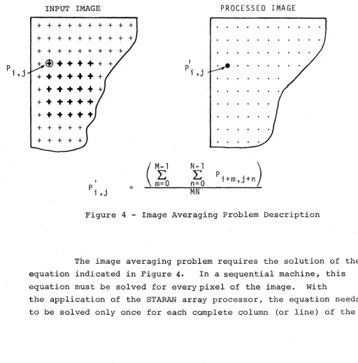
This image averaging technique requires that a new gray
value be computed for each specified pixel of the input image. This
P. .
1 ,J
GOODYEAR AEROSPACE CORPORATION
GER-16227
within the boundaries of a specified matrix cell such that the
image pixel of interest is located in the top left corner. This
process is shown by sketch and equation in Figure 4 below.
INPUT IMAGE
+ + + + + + + + + +
+ + + + + + + +
+ + + + + +
+@++++++
+++++++
+++++++
+
+
+
+
+
+
+ +
I
P. .
1 ,J
=
I P. .
1 ,J
N-l
E
n=QMN
PROCESSED IMAGE
•
•
• •P. l+m,J+n . )
Figure 4 - Image Averaging Problem Description
The image averaging problem requires the solution of the
equation indicated in Figure 4. In a sequential machine, this
equation must be solved for every pixel of the image. With
the application of the STARAN array processor, the equation needs
to be solved only once for each complete column (or line) of the
[image:37.620.42.554.212.730.2]-30-GOODYEAR AEROSPACE
CORPORATION
GER-16227
image. The STARAN system configurations shown in Figure 3A
utilized in the solution of this problem. The size of the input
image is assumed to be 512 pixels by 512 pixels with 8 bits to
describe gray level for each pixel. Two 256 bit X 256 bit
associa-tive arrays are assumed within the STARAN system configuration. For
the purpose of a timing estimate, the size of the averaging matrix
cell will be fixed at 5 X 5 pixels, i.e., M
=
5 and N=
5 (seeFigure 4), for a total of 25 pixels.
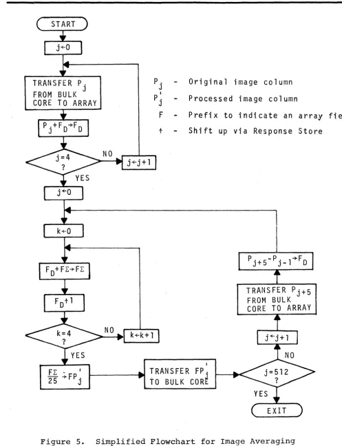
The simplified flow chart shown in Figure 5 shows the
technique used in applying STARAN to the solution of the image
aver-aging problem. This flow chart does not show the transfer of the
image betwe~n the disc and STARAN bulk core, but, i t does show
transfer between 'STARAN bulk core and the associative arrays along
with the actual array processing.
The array processing time for the image averaging problem
was estimated at 0.165 seconds based on a 2 - array system. This
estimate is developed, in detail, in Appendix N of volume II.
Apply-ing the usual technique of addApply-ing 25 percent for overhead, brApply-ings
the estimated time up to 0.21 seconds. The I/O times are essentially
equal to those developed for convolution (item (3) above. The time
for the total process, including overhead and based on the use of 2
arrays and conventional disc I/O, is developed below:
Array computations
Input/Output
Disc to Bulk Core Bulk Core to Array
Array to Bulk Core
Bulk Core to Disc
Total
0.21 sec
1.1 sec 0.4 sec
0.4 sec
1.1 sec
[image:38.615.71.579.400.779.2]TRANSFER P.
P .Original
FROM BULK
JJ
I
P .
Processed
CORE TO ARRAY
JF
Prefix to
t
Shift up
I
1 - - - - -_____ ~RANSFER
FP
jTO BULK CORE
GOODVEAR AEROSPACE
COAPOA"TION GER-16227
image column
image column
indicate an array
via Response Store
TRANSFER
P
j+5
FROM BULK
CORE TO ARRAY
field
Figure 5. Simplified Flowchart for Image Averaging
[image:39.618.65.562.72.720.2]-32-GOODYEAR AEROSPACE CORPORATION
GER-16227
By using extended memory parallel I/O (EM/PIO) architecture
(See Figure 3B) the I/O time can be reduced to 0.008 sec for a 2
array system, or 0.004 sec for a 4-array system. This results in
total processing times of 0.22 sec and 0;11 sec, respectively.
For comparison, the following execution times for sequential
computers are given below:
IBM 360/195 IBM 360/65
8.04 sec (CPU time)
60.0 sec (CPU time)
The above times are actual measured times supplied by the
customer agency. Since they represent only CPU times (not I/O), they
are directly comparable to the STARAN times for performing only the
array computations. Therefore, STARAN provides the following
per-formation advantages over the fastest sequential machine:
2 array STARAN vs IBM 360/195 = 8.05/0.21 = 38
4 array STARAN vs IBM 360/195
=
8.05/0.105=
77b. Text Search
(1) Problem Description
The text search problem requires searching a very large
textual data base in order to locate the documents which contain a
particular combination of query words. The query words do not have
to appear in any particular order in a document. The textual data
base to be searched is made up of about 105,000 documents, each
document averaging a little over 300 words and 6 characters per word
for a total of 200 X 106 characters (or bytes). For those documents
that meet the conditions imposed by the query statement, the minimum
GOODVEAR AEROSPACE CORPORATION
GER-l6227
The query statement is made up of a combination of logical
unions and intersections of single words, and can be described by
the following expression:
The groups of words inside each set of parenthesis are
usually synonyms or at least similar words. In order to meet fully
the search requirements, a given document must contain at least
I query word from each and every intersecting (parenthetical) group
of query words. Since more than one document could meet the
require-ments of the query statement, the entire data pase must be searched.
The design goal for solution of this problem is I second.
(2) Problem Solution
The major time-consuming aspects of this problem are: 1) I/O
time, and 2) search time. Other aspects of the problem are essentially
negligible from the standpoint of time. While any machine could solve
this problem, most could not approach the design goal of I second.
In applying STARAN to this problem, two approaches were
considered based on the two system configurations shown in Figure 3
views C and D. The fastest method (Figu're 3D) is based on the
specifications of the solid state mass memory to be developed by
RADC in the near future. This approach results in a system which
nearly meets the design goal.
The alternate method (Figure 3 view C) is based on the use
of a conventional disc memory, specifically the type 3330 disc system.
While this method results in longer response time, i t provides a
nearer-term alternative which is still fast in comparison with
exist-ing systems which are based on sequential processors.
-34-(
GOODVEAR AEROSPACE CORPORATION
GER-16227
Both STARAN approaches are based on the transfer of the textual data base from the mass memory media to the arrays in the
same format via a special purpose controller. The controller must
have the ability to sense word beginnings. The text data is stored
in the arrays horizontally in three columns. The text words are
left justified in these columns to a specific bit position. Each
array provides storage for 2 documents. Both approaches to the
problem utilize multiple arrays and all arrays used must conform
to the same format since the search is performed simultaneously in
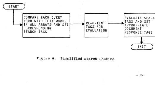
all arrays. The same search strategy is used in both STARAN
approaches and is shown in the simplified flow chart of Figure 6.
The query statement is stored in STARAN bulk core and is made up
of query words which are transferred sequentially to the common
register, from which a search is performed by an exact match with
all text words stored in the arrays. The responses to the query
word searches are stored in designated tag columns. After all
query words have been used to search the text stored in the arrays,
the tag columns are evaluated in accordance with the logical opera-tors that appear in the query statement.