2016 International Conference on Artificial Intelligence and Computer Science (AICS 2016) ISBN: 978-1-60595-411-0
The Control System Development of Electronic Mechanical
Continuous Variable Transmission
Xiu-min YANG
1,*, Yang-yang ZHAO
2, Li-xia LI
1and Chun-yang ZHOU
31School of Automation, Shenyang Institute of Engineering, 110136 Shenyang, P.R. China
2School of Electric Power, Shenyang Institute of Engineering, 110136 Shenyang, P.R. China
3Engineering Training Center, Shenyang Institute of Engineering, 110136 Shenyang, P.R. China
Keywords: EMCVT, Control requirement, Control system, Hardware circuit.
Abstract. The electronic mechanical continuous variable transmission (EMCVT) was a metal-belt type continuously variable transmission of new structure. Based on the mechanical structure of EMCVT, the mathematic model of both the matching clutch and speed regulating system was established, while the control requirements were analyzed and hardware circuit was designed. According to the simulation experiment, bench test and loading test with hardware equipment, the control system designed achieved a desired control expectation being stable and robustness, which verifies the correctness of theoretical analysis.
Introduction
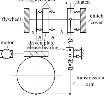
[image:1.612.157.454.517.705.2]Due to simple structure and easy to control, the metal belt type continuously variable transmission can run smoothly with a wide range of speed ratio, which has been applied in the power transmission field of automobiles. At present, all the continuously variable transmissions use the hydraulic system and boost the pressure of cone-plate to achieve variable speed control. A new structure EMCVT was studied in this paper. The EMCVT used rolling screw mechanism to boost the pressure of cone-plate and reached the speed governing with an electrical machinery speed control mechanism. Compare with conventional continuously variable transmission, the significant modification is to abandon the hydraulic system, having a huge advantage on control, environmental protection and cost. As shown in the figure1, the cone-plate of driven shaft steps up towards inside, making the metal belt moving towards outside. The cone-plate of driving shaft steps up towards outside, making the metal belt
Figure 1. The principle figure of EMCVT.
1-Clutch
2-Driving fixed cone-plate shaft
3-Metal V-belt 4-Driving movable cone-plate 5,13-Disc spring 6-DC motor 7-Reduction gear 8-Screw
9-Nut
10-Driven fixed cone-plate shaft
moving towards inside. Therefore, the transmission radiuses of both driving shaft and driven shaft are resized. In a similar way, driving movable cone-plate of driving shaft moves towards inside and driven movable cone-plate of driven shaft moves towards outside, up to reducing to the minimum value for speed radio. In order to obtain the specific speed radio, the move location of cone-plate needs to be controlled accurately to control the transmission radius of metal belt.
Dynamic torque transferred from clutch to driving static cone-plate, the disc spring boosts the pressure of movable cone-plate by screw mechanism, tightening the Metal V-belt. Using friction, the Metal V-belt transferred the power to the driven movable cone-plates and output the power. Afterwards, the synchronizer and reversing mechanism are set to achieve the change of output rotation direction, which is the same as the reverse institutions of mechanical transmission.
Control Requirements and Model Establishment for EMCVT
The control system of EMCVT, whose actuator is the direct current machine, has only two missions including controlling the clutch and changing the speed radio.
Control structure of the clutch and Control Model
[image:2.612.214.397.386.551.2]The driving mechanism of clutch is simplified as shown in figure 2. It composes of permanent magnet DC machine, worm gearing deceleration institutions, spring compensation mechanism, position senor, mechanical limit mechanism and inhaul cable. The worm gearing deceleration institutions have a function of self-locking. The positive and negative of electric machine pull the inhaul cable, achieving the engagement and separation. In the process of separation, the load of electric machine is the sum of the clutch load and the worm gearing friction load, while the load of electric machine is the difference value between the clutch load and the worm gearing friction load in the process of engagement.
Figure 2. Automatic clutch structure driven by motor.
According to the figure 2, the motion equation of electric machine is such as formula (1).
2
2 a
a a a a e
e L m
e m a
di d
u L R i C
dt dt
d d
T T J f
dt dt
T c i
(1)
In the formula, uais the armature voltage of electric machine, La is the armature inductance, Ceis
the EMF coefficient, Te is the electromagnetic torque, TLis the output torque of worm, J is the rotati onal inertia of electric machine, fmis the viscous drag coefficient, cmis the torque constant, iais the
Ignoring the rotational inertia of worm, when the clutch is in engagement or separation, the follow ing formula (2) was established.
tan
tan( )
L c
T T
(2)
In the formula, γ is the lead angle of worm, φ is equivalent friction angle of worm and gear. For se lf-locking type worm gear and worm, φ>γ. Tcis the worm wheel torque equivalent of small end elast ic of diaphragm spring.
Speed Governing Device and Speed Ratio Control Model for EMCVT
The control of transmission ratio of continuously variable transmission was accomplished by nut rotation of rolling screw, where the DC electric machine drives a two-stage gear retarding mechanis m. Based on the rolling screw, nut rotation translates into rectilinear translation of screw. The move ment of screw boosts the pressure of belleville spring and push movement of cone-plate, achieving c hanging the transmission radio ultimately, as shown in figure 1.
Compared with common manual transmission and automatic mechanical transmission, the biggest advantage for EMCVT is that it can realize the continuous change of transmission radio and remove the ladder-like change of speed radio.
The actual input and output rotational speeds were gathered to the control system of EMCVT. Th en, compared with the target speed ratio, the speed ratio of EMCVT can been controlled. The transm ission speed ratio of EMCVT is defined as follows:
DR DN R R n n i
2 1
(3)
In the formula, n1is the driving cone-plate speed, n2is the driven cone-plate speed, RDRis the action
radius of driving cone-plate, RDNis the action radius of driven cone-plate.
In the process of variable speed, the central moment between the two belt wheels of EMCVT is fixed. Because the length change caused by elastic deformation is very small, the length of metal belt can be regarded as a constant value. So the length L is as formula (4).
2 ) ( 2 ) 2 cos
( R R d
L DR DN (4)
In the formula, L is the length of metal belt, dis the center distance of transmission shaft, is the oblique running angle of driving belt. According to the geometrical relationship, thecan be expressed as formula (5).
( )
sin RDR RDN
d
(5) Combined with formula (4) and formula (5), the proximate calculation between the speed radio and the radius of driving cone-plate is as formula (6).
2
( 4 )
2
B B AC i
A
(6)
In the formula, A RDR/d,B 2RDR/d,C RDR/d 2d/RDR L/RDR. The relation b etween the axial displacement xp of driving cone-plate of driving pulley and transmission ratio i is as formula (7).
max
min
/ (2 tan ) / (2 tan )
DN p DR p R x i R x
In the formula, RDNmaxis the maximum working radius of driven belt pulley, RDRminis the minimu
m working radius of driving belt pulley, is the taper angle of straight edge line cone-plate.
The Hardware Design of Control System for EMCVT
The control system hardware circuit of single-chip microcomputer for EMCVT is composed of micr oprocessor, sensors, power circuit, reset circuit, peripheral signal processing circuit and serial comm unication circuit. Its main principle is as follows. At first, the signals such as engine output rotation speed, output speed of EMCVT, position signal of cone-plate, clutch position signal, throttle percent age signal, braking signal, brake signal, tap position signal were gathered by all the sensors. After th e signal conditioning circuit, rectification, smoothing and amplification, the output signals of sensor s were gathered in the microcontroller. When analyzing and processing the signal data, microcontrol ler can monitor the operation condition of power system. Meanwhile, the microcontroller can call th e corresponding control procedures that transmission ratio of EMCVT was adjusted by controlling r otate of adjustable-speed electric machine and the clutch was controlled by controlling rotate of the clutch electric machine. Therefore, the power system works according to the ideal performance. For example, by adjusting the speed ratio, the prime mover maintained ideal working point and by contr olling the clutch, it can realize a smooth engagement or separation under the different operating con ditions. The electronic control system has a higher performance price ratio, strong anti-jamming cap acity, high safety and reliability.
Control System Hardware Design of Single-chip Microcomputer
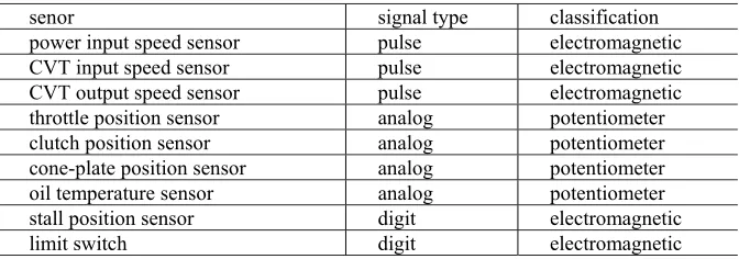
[image:4.612.139.475.431.549.2]The system mainly uses two kinds of sensors, the hall pulse sensor and the angular displacement sen sor. The input speed of power system and the output shaft speed of EMCVT acquire the speed signal s by hall pulse sensors, outputting pulse signal. The angular displacement sensors of throttle percent age, clutch position and cone-plate position output voltage analog signal, as shown in table 1
Table 1. Main types and functions of sensors.
senor signal type classification
power input speed sensor pulse electromagnetic
CVT input speed sensor pulse electromagnetic
CVT output speed sensor pulse electromagnetic
throttle position sensor analog potentiometer
clutch position sensor analog potentiometer
cone-plate position sensor analog potentiometer
oil temperature sensor analog potentiometer
stall position sensor digit electromagnetic
limit switch digit electromagnetic
The hardware structure principle diagram of control system for EMCVT is as shown in figure 3. The system is mainly composed by clock circuit, power circuit, reset circuit, analog signal input circuit, pulse signal processing circuit, on-off signal processing circuit, microprocessor, power driver circuit and alarm display circuit.
The direct-current motor has a function of bipolar drive by driver chip of LMD18200, using the fixed frequency PWM method to adjust the speed of direct-current motor
The Main Interface Circuit Design
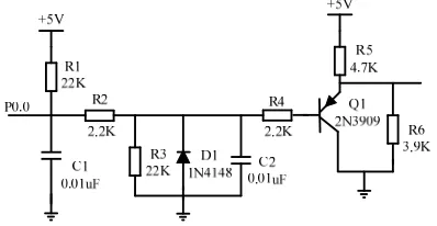
Circuit Design of Speed Measuring
Figure 3. The hardware structure diagram of control system for EMCVT.
Figure 4. Rotating speed measurement circuit. Input processing circuit of analog signal
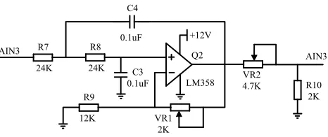
All the senor outputs of cone-plate position, clutch position, throttle valve are the analog signal. After RC filter circuit to filter the high frequency noise, the input signals are transmitted to the input end of amplifier. The integrated operational amplifier with high input impedances and low output impedances has a function of impedance conversion. The feedback was applied in the circuit, not only to obtain the necessary closed loop gain and improve signal to noise ratio, but also to expand the working frequency and reduce nonlinear error. The input processing circuit of analog signals is as shown in figure 5.
In addition, as an interface element of digit circuit, the photoelectric coupler restrains the interference noises of binary signals effectively. To avoid mutual interference and guarantee working reliability of the whole control system, the master control circuit and power-driven circuit are controlled and packaged separately.
[image:5.612.214.413.399.502.2]AIN3
R10 2K
12K VR1
2K 0.1uF
C4
R9
C3 0.1uF 24K R8
24K R7
AIN3 Q2
LM358 +12V
[image:6.612.197.430.75.173.2]VR2 4.7K
Figure 5. The analog signal processing circuit.
clutch control adopts the fuzzy-PID method to recognize position. The speed radio control adopts the control strategy of target tracking digital PID.
At present, by bench test and actual operation, the control system has achieved the control task, having a stronger stability and performance of anti-jamming.
Conclusion
EMCVT is a new type continuously variable transmission. EMCVT uses a DC motor to control rolling screw to boost the pressure of cone-plate for speed adjustment. Also the clutch is driven by another DC motor. Considering structural features and control requirements of EMCVT, the control system was designed. According to bench contrast test and service test with hardware equipment, it had a stronger stability and performance of robustness, which verifies the correctness of theoretical analysis.
Acknowledgement
This research was financially supported by the science and technology funds from Liaoning Educati on Department (serial number: L2015375).
References
[1] Lei Zhang, Xiumin Yang, Tao Wei, Yingdi Shi, The Working Mechanism and Control Method of GL160C Metal Belt CVT, Advanced Materials Research, 139-141 (2010) 1856-1859.
[2] Lei Zhang, Guili Hao, Xiumin Yang, Chunyang Zhou, The Electric Vehicle Power Design and The Matching Characteristics Analysis of The Transmission System. Telkomnika Indonesian Journal of Electrical Engineering, 11(2013) 6352-6357.