Journal of Chemical and Pharmaceutical Research, 2014, 6(2):307-315
Research Article
CODEN(USA) : JCPRC5
ISSN : 0975-7384
A mathematical model and the corresponding software for combining
selective catalytic reduction with regenerative heat exchange
Zhongjun Tian and Shipin Jin*
School of Energy and Power Engineering, Huazhong University of Science and Technology,
Wuhan, P. R. China
_____________________________________________________________________________________________
ABSTRACT
In order to achieve dual goals of waste heat recovery and nitrogen oxides (NOx) removal in fuel gas from High Temperature Air Combustion (HiTAC) furnaces and coal-fired boilers in power plants, the honeycombed Selective Catalytic Reduction (SCR) catalysts were implanted in the regenerative heat exchange system. Under the premise of ignoring the influence of catalytic reaction on the heat transfer process, the single channel one-dimensional mathematical model for catalytic reduction and regenerative heat exchange of NO was established at unsteady state, in which the adsorption and reaction of reactants obeyed the Eley-Rideal Mechanism. With governing equation dispersion via the finite-volume method and calculation program compiled based on C# language in Visual Studio 2010, a corresponding calculation software was developed. The preliminary analysis of simulation results validated the rationality of the model.
Keywords:Heat exchange; HiTAC; Mathematical model; Regenerative SCR; Software.
_____________________________________________________________________________________________
INTRODUCTION
Recently, the massive increase in energy consumption has encouraged progressively deteriorating issues of energy shortage and environmental pollution. In order to conserve energy and reduce emissions, numerous advanced technologies including regenerative heat exchange [1] and SCR [2], two relatively mature technologies, have been developed. The former is widely applied to waste heat recovery in HiTAC[3] industrial furnaces, and the latter is widely used to remove NOx in coal-fired boilers of power plants. Both possess a high efficiency of above 80%.
However, it tends to readily generate excess NOxin the case of high combustion temperature [4], oil fuel [5], and the
complicated combution surroundings in HiTAC furnaces. In power plants, high waste heat recovery efficiency needs huge heat transfer equipment, which occupies large area and also costs much money.
To treat the flue gas, the regenerators, a key part of regenerative heat exchanger technology, has a similar geometry with SCR catalysts after adopting honeycomb ceramics and the placement that allowed regenerators and catalysts to superimpose on each other was helpful for the displacement among cells. Therefore, two technologies were considered to be combined, that is, regenerators with suitable temperature regimes for SCR catalyst reactions (temperature windows) were replaced by catalysts in regenerative heat exchange system. NH3 injected at proper
Figure 1. The Principle of the Coupled Technology
A considerable amount of research has been conducted during the last few decades seeking to better understand the details of heat exchange modes[6-7] and SCR denitration modes[8-9], and abundant computation experiences are accumulated. The compound mode which integrates governing equations of flow, heat and mass transfer, and catalytic reaction was established in this paper. The one-dimensional model was employed in view of the complicated cases and corresponding simulation software was programmed. The analysis of numerical results verified the rationality and practical value of the model.
1. COMBINED MODEL
A mathematical model concerning SCR denitration and regenerative heat exchange was proposed to preliminarily investigate the aforementioned combined technology. The model was expounded in detail hereinafter.
Square channels were adopted for catalysts and regenerators in simulation, and it was replaced by the equivalent sectional sizes cylinder. The model was built under these assumptions due to the complicated situation: (1), the inlet mixture gas parameters are constant; (2), the heat exchange process in all channels is the same; (3), the gas density is determined by its temperature; (4), both the gas thermal conductivity and the solid radial thermal conductivity are zero; (5), the catalytic reaction has no influence on the heat transfer process; (6), the temperature of catalytic reaction is the local solid temperature; and (7), the diffusion of gas components in the micropore is ignored. The model is as follows:
1) Regenerative heat exchange model 1. Gas phase mass balance:
g g 0g z u t
(1)2. Gas phase energy balance:
g V , ,
g pg g g pg gha
T
sT
gz
T
uc
t
T
c
(2)3. Solid phase energy balance:
g V s s p, 1
s ha Tg Ts
t T c
( 3 )
4. Relationship between gas temperature and its density:
g g
0 g R T
p
(4) Heat transfer coefficient was obtained from the reference [11]:
Gz
G
Nu
exp
60
.
2
z
1000
18
.
13
364
.
4
0.524 (5)Where the subscripts g and s represent gas and solid, respectively; ρ is density; cp is special heat capacity; T is
temperature;tis time;uis velocity;u0is standard state velocity;zis axial coordinate;deiis equivalent diameter;p0is
standard state pressure; εg is porosity of porous medium; Di is diffusion coefficient; Di,N2 is binary diffusion
coefficient;Rgis gas constant;Nuis Nusselt nuber;Gzis Graetz number.
2) SCR model
The majority of NOxis NO in flue gas. When the concentration of O2exceeds 1%, the main reaction is:
2 2 2
3 4NO O 6HO 4N
Adsorption and reaction of reactants follows Eley-Rideal mechanism. NH3is firstly attached to the solid surface of
catalyst in chemical adsorption, and desorption of NH3is simultaneous. Then NO reacts with NH3attached to the
catalyst surface and finally products desorb and spread out. The govening equations are as follows:
1. NO mass balances in channel:
g NO f , NO V NO NO g NO C C a h z C u t C , (7)2. NH3mass balances in channel:
g NH f , NH V NH NH gNH3 3 3 3 3
C C a h z C u t C (8)3. Solid phase mass balance:
red , NH des , NH ads , NH NH 3 3 3
3 R R R
t
Ω
(9)
4. The adsorption rate of NH3on the catalyst surface is assumed to be proportional to the NH3concentration in the
gas phase:
des , NH ads , NH g f , NH NH V NH f , NH 3 3 3 3 3 31 R R
C C a h t C
(10)5. NO reaction in catalyst interface:
f NO, g f , NO NO V NO f NO, 1 R C C a h t C (11) Where: m g i 0 i V T y TC (12)
The NO reduction reaction is considered to be of first order with respect to each reactant:
Ω C k R R 3 3 red NO NH
NH
NO
The adsorption rate of NH3on the catalyst surface is assumed :
ΩC k R
3 3 3,ads ads NH NH
NH 1
while the rate of desorption is assumed to be proportional to the concentration of the adsorbed species:
Ω C k R 3 3 3,des des NH NH
NH
An Arrhenius type dependence of the kinetic constantskis assumed
red s
red
red A exp E RT
k
ads s
ads
ads A exp E RT
k
des s
des
des A exp E RT
k
Where,
NH3
0 des desE 1
E
Mass transfer coefficient:
ei i g i Sh d D
h
(13)Here the diffusion coefficient of i equals the binary diffusion coefficient of i:
2 1 N i 2 3 1 N 3 1 i 0 1.5 5 -i.N i 2 2 2 1 1 10 4.36 M M V V p T D D (14)Here, the subscripts ads, des, and red stand for adsorption, desorption, and reduction respectively, i represents component, f represents value at the gas-solid interface. Ciis mole concentration of reactants, Ri reactive rate, yi
volume fraction, Vmmolar volume,A pre-exponential factor,Eactivation energy,θisurface coverage, βparameter
molecular diffusion volume,Mimolecular mass.
Boundary conditions:
Heating process:
T
0
,
t
T
fg,in,y
i
0
,
t
y
i,in,
nt
sw
t
n
1
t
sw
;Cooling process:
T
z
1,
t
T
a,in,y
i
0
,
t
y
i,in,
n
1
t
sw
t
n
2
t
sw
.Here Tfg,in is inlet flue gas temperature, z1overall length of channel, Ta,in inlet air temperature, yi,in inlet volume
fraction,tswswitching time,n=1, 2, 3, …
The finite volume method is adopted to calculate the model; meanwhile, the independence of the grids has been proved.
Heat recovery efficiency is described by
in m, in m,
in a, in a, out a, out a, Q
T W
T W T W
x (15)
Where:W
cpu, W t W
tdtt
sw
0 a,out sw
out a,
1
,
T
t
dt
t
T
tsw0 a,out sw
out a,
1
Denitrification performance was evaluated by the conversion of NO (denitrification efficiency). As the temperature of gas changed instantaneously, volume percentage was employed for calculation.
NO conversion is calculated by
in NO,
out NO, in NO, NO
y y y
x (16)
Where: y t
0tswyNO,out
tdt swout NO,
1
Space velocity is defined by
ca 0
V
F
SV
(17)Where, represents time–weighted averaged, Wis water equivalent,yNO,outoutlet NO concentration,F0standard
flow conditions of gas mixture,Vcathe volume of catalyst,z1the length of catalyst channel.
2. SIMULATION SOFTWARE
2.1 COMPUTATION PROCEDURES
This program was written in C# language based on the Visual Studio 2010 platform. Heat exchange computation at unsteady state unidirectionally affected the catalytic computation due to the fact that the effect of catalytic reaction on heat exchange process was ignored. Therefore, the computation procedure was simplified as follows:
1) The discrete equations obtained from governing equation were iteratively computed from initialization. The results included flue gas temperature, velocity fields and solid temperature field. Residuals needed to satisfy the convergence requirement before the process reached the next time step size. When periodic steady state was reached, the relevant data of gas and solid was substituted into the catalytic discrete equations.
2) SCR catalytic discrete equations were iteratively computed and the next time step size started when the residuals satisfied the new criterion for convergence of iteration.
Figure 2. The Computation Procedure
2.2 INTRODUCTION OF SOFTWARE
The software consisted of four modules: 1, parameter collection and transmission module: gather the data on the user interface and assign them to the software; 2, heat exchange computation module: obtain data at different times by iterative calculation; 3, catalytic reaction module: calculate the SCR reaction concentration field; 4, results collection and save module: collect the data calculated and save it into the EXCEL files.
The factors which affect the regenerative heat exchanger can be various, and users can modify the relevant parameters according to the actual calculation or directly change it in program.
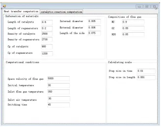
Regenerative heat exchange parameter interface was depicted in figure 3:
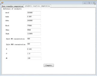
[image:5.595.142.471.411.671.2]SCR denitrification parameter interface was displayed in figure 4:
Figure 4. Input Port of Denitration Simulation Computation
3 SOFTWARE VALIDATIONS
3.1 SIMULATION CONDITIONS
The physical model was established via referring to the relevant experiments [12]. Conventional honeycomb catalysts V2O5–WO3(MoO3)/TiO2and honeycomb regenerators Al2O3were adopted in the simulation. The inner and
outer boundary equivalent diameters of square channel were 5 and 6mm, respectively. The flue gas firstly flowed through catalysts and then flowed through the regenerators. The catalyst duct length and regenerator duct length were 0.6m and 0.2m, respectively. The density and special heat capacity of two materials were listed in table 1, and the catalytic reaction parameters could be found in table 2. The flue gas consisted of 5% v/v O2, 5% v/v H2O, NO,
and NH3. The balance gas is N2. The volume flow of the mixture equaled that of the air available for cool gas in the
system. Unless intentionally noted, the space velocitySV=5000h-1, flue gas temperatureTfg,in=350℃; NO and NH3
concentrationyNO,in=yNH3,in=400ppm; switching timetsw=45s.
Table 1 Physical Properties of the Material
Parameters Catalysts [13] Regenerators[14] Special heat capacity/J kg-1·k-1 900 2730 density/kg·m-3 2500 1200
Table 2 Kinetic Parameters of Ccatalysts
Kinetic parameters values
Ared/s-1 3.23×10 5
Ered/ J·mol-1 77500
Aads/ m3·mol-1·s-1 0.887
Eads/ J·mol-1 9540
Ades/ s-1 2.43×10 5
0 des
E / J·mol-1 113970
β 0.163
Ω/ mol·m3 130
RESULTS
[image:7.595.196.412.186.352.2]3.2.1 ANALYSIS OF HEAT TRANSFER
Figure 5. Change of Temperature at Different Locations
As can be seen from figure 5, temperature of gas and solid in different position periodically fluctuates with time. Solid temperature is lower than flue gas temperature when flue gas flows and higher than air temperature when air flows, which coincides with the actual situation of regenerative heat exchange. In addition, air temperature in catalyst layer is lower than flue gas temperature at the same position, which indicates that catalysts have an extremely good heat storage capacity and their material is suitable as a regenerative material.
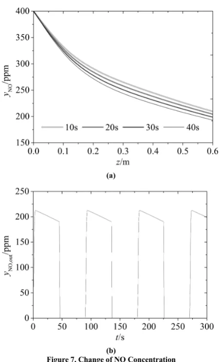
[image:7.595.201.410.445.600.2](a)
[image:8.595.192.417.67.438.2](b)
Figure 7. Change of NO Concentration
As can be seen from the figure 6, the simulation values of heat recovery efficiency and the experimental values[12] of similar materials gradually decrease with switching time prolonging, which demonstrates that both have the same observable change tendencies despite the presence of deviation from material property difference and model simplification. The reason is that the longer switching time is, the smaller the temperature differences between gas and solid are, which indicates that catalysts have a fairly desirable heat storage-release property and the developed catalyst material is a suitable storage material.
3.2.2 CHANGE OF NO CONCENTRATION
Figure 7 a reveals that NO concentration around inlet decreases axially and rapidly due to the fact that the temperature is high and catalytic reaction proceeds strongly. Therefore, the denitrification efficiency is relatively high. Nevertheless, reaction intensity weakens in the low temperature area in downstream and the concentration profile changes gently. In Figure 7 b, a periodic change of outlet NO concentration with time is observed, and each period has a linear decrease. Period variety is resulted from change of gas flow direction. When the flue gas flows, the temperature gradually increases and the denitration reaction strengthens, leading to linear decrease of outlet NO concentration.
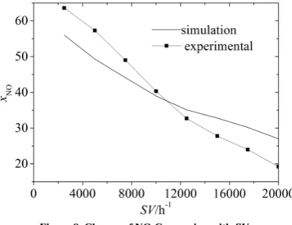
Figure 8. Change of NO Conversion with SV
Figure 8 shows that simulation and experimental denitration efficiency[12] presents a linear decrease with the increase of space velocity. That is because the increase in space velocity results in the increase of corresponding gas velocity. The reactant residence time in catalyst shortens and thus reactant effective reaction time becomes shorter, which leads to the decrease of denitration efficiency.
In a word, these analysis results, in a manner, could be verified by relevant experiments conducted by us, in which a V2O5–WO3(MoO3)/TiO2catalyst was used. The model can predict the project and has a certain reference value.
CONCLUSION
In order to obtain dual goals of waste heat recovery and nitrogen oxides (NOx) removal, the one-dimensional
mathematical model combining selective catalytic reduction with regenerative heat exchanger was established. Complied in C# language, the simple simulation software was developed. The simulation calculation was performed according to the related parameters and its physical properties of V2O5–WO3(MoO3)/TiO2catalyst in the literature,
which was widely applied in coal-fired power plant boilers. The results indicated that catalysts had a fairly desirable heat storage-release property. NO concentration axially decreased rapidly and then remained almost unchanged. The outlet NO concentration periodically changed with time and there existed a linearly decreased segment in each period. The denitrification efficiency decreased with space velocity increasing. Compared with the experiment results, the model possessed a certain rationality, which could lay a foundation for the model optimization in the future.
REFERENCES
[1] GF Nellis; A Sanford,International Journal of Heat and Mass Transfer,2006, 49: 329−340. [2] K Skalska; SM Jacek; S Ledakowicz,Science of the Total Environment,2010, 408: 3976–3989. [3] N Radi; W Blasiak,Applied Thermal Engineering,2006, 26: 2027−2034.
[4] A Khoshhal; M Rahimi; AA Alsaira, International Communications in Heat and Mass Transfer,2011, 38: 1421−1427.
[5] SR Wu; WC Chang;J Chiao,Fuel,2007, 86: 820−828. [6] F Duprat; GL Lopez,Int J Energy Res,2001, 25: 319- 329.
[7] MT Zarrinehkafsh; SM Sadrameli,Applied Thermal Engineering,2004, 24: 373-382. [8] G Schaub; D Unrtth; J Wang,Chemical Engineering and Processing,2003, 42(5),365-371. [9] JW Beeckman; LL Hegedus,Ind.Eng.Chem.Res.,1991,30(5),969-978.
[10] RK Shah, DP Sekulić, Fundamentals of heat exchanger design, USA: John Wiley and Sons, Inc.,2003.
[11] RE Hayes, ST Kolaczkowski, Introduction to catalytic combustion, U K: Gordon and Breach Science Publishers, Reading ,1997.