http://dx.doi.org/10.4236/cn.2013.54037
A High Spectral Efficient Non-Binary TCM Scheme-Based
Novel Decoding Algorithm for 4G Systems
Riyadh A. Al-Hilali1, Raad H. Thaher1, Abdulkareem S. Abdallah2
1College of Engineering, Al-Mustansiriya University, Baghdad, Iraq 2College of Engineering, Basrah University, Basrah, Iraq
Email: [email protected], [email protected], [email protected] Received July 1, 2013; revised July 30, 2013; accepted August 10, 2013
Copyright © 2013 Riyadh A. Al-Hilali et al. This is an open access article distributed under the Creative Commons Attribution Li- cense, which permits unrestricted use, distribution, and reproduction in any medium, provided the original work is properly cited.
ABSTRACT
This paper deals with the MIMO-OFDM technique that is applied to the fourth generation (4G) of the wireless com- munication systems, this technique can provide high data rate transmission without increasing transmit power and ex- panding bandwidth, it can also efficiently use space resources and has a bright future. It presents the channel coding assisted STBC-OFDM systems, and employs the Coded Modulation techniques (CM), since the signal bandwidth avail- able for wireless communications is limited. The proposed system deals with Non-binary error control coding of the TCM-aided STBC-OFDM scheme for transmissions over the Rayleigh channel. A new non-binary decoding method, Yaletharatalhussein decoding algorithm, is designed and implemented for decoding non-binary convolutional codes, which is based on the trellis diagram representing the convolutional encoder. Yaletharatalhussein decoding algorithm outperforms the Viterbi algorithm and other algorithms in its simplicity, very small computational complexity, decoding reliability for high states TCM codes that are suitable for Fourth-Generation (4G), decreasing errors with increasing word length, and easy to implement with real-time applications. The simulation results show that the performance of the non-binary TCM-based Yaletharatalhussein decoding algorithm-assisted STBC-OFDM scheme outperforms the binary and non-binary decoding methods.
Keywords: Convolutional Codes; Trellis Code Modulation(TCM); Non-Binary Error Correcting Codes; Groups; Rings of Integers; OFDM; MIMO; MIMO-OFDM; STBC
1. Introduction
The fourth generation of wireless communications refers to a collection of technologies and standards that will find their way into a range of new ubiquitous computing and connections systems. 4G offers the promise of al- lowing users to connect to the Internet and one another through a variety of devices and standards anytime, anywhere, and at a wide range of speeds, from narrow- band to broadband [1,2]. The main key features of 4G are receiving a large volume of information, data, pictures, video and so on. As a key building block of next-genera- tion wireless communication systems, MIMOs are capa- ble of supporting significantly higher data rates than the Universal Mobile Telecommunications System (UMTS) and the High-Speed Downlink Packet Access (HSDPA) based 3G networks [3]. A MIMO system is capable of exploiting transmitter and receiver diversity, hence main- taining reliable communications. To overcome a multi-
path-fading environment with low complexity and to achieve wireless broadband multimedia communication systems (WBMCS), the orthogonal frequency-division multiplexing (OFDM) transmission scheme is employed [4]. OFDM is one of the applications of a parallel-data- transmission scheme, which reduces the influence of multipath fading and makes complex equalizers unnec- essary. Advances in coding, such as turbo [5] and low density parity check codes [6], made it feasible to ap- proach the Shannon capacity limit [7] in systems with a single antenna link. Significant further advances in spec- tral efficiency are available through increasing the num- ber of antennas at both the transmitter and the receiver [8-10].
OFDM system employing Quadrature Amplitude Modu- lation (QAM) in Rayleigh fading channel, since the use of multiple antennas at both ends of a wireless link (mul- tiple-input multiple output (MIMO) technology) has re- cently been demonstrated to have the potential of achiev- ing extraordinary data rates. Orthogonal frequency divi- sion multiplexing (OFDM) significantly reduces receiver complexity in wireless broadband systems. The use of MIMO technology in combination with OFDM, i.e., MIMO-OFDM therefore seems to be an attractive solu- tion for future broadband wireless systems.
L. Hanzo et al. [13] presented that the CM-assisted STBC schemes were found to significantly improve the system’s achievable performance. Furthermore, the TTCM- STBC concatenated scheme was observed to give the best performance among all the CM-STBC concatenated schemes. Also, the TTCM-assisted G2 coded OFDM scheme gives a better performance than the LDPC-as- sisted G2 coded OFDM scheme. Furthermore, in the context of the achievable coding gain versus complexity performance, it is found that the TTCM-assisted schemes are capable of achieving higher coding gains in the rela- tively high-complexity range, than the LDPC-assisted candidate schemes.
2. OFDM, MIMO, and MIMO-OFDM
The principle of multi-carrier transmission is to convert a serial high rate data stream on to multiple parallel low rate sub-streams. Each sub-stream is modulated on an- other sub-carrier. Since the symbol rate on each sub- carrier is much less than the initial serial data symbol rate, the effects of delay spread, i.e. ISI, significantly decrease, reducing the complexity of the equalizer. OFDM is a low complex technique used to modulate multiple sub-carri- ers efficiently by using digital signal processing [14-17]. An important design goal for a multi-carrier transmission scheme based on OFDM in a mobile radio channel is that the channel can be considered as time-invariant during one OFDM symbol and that fading per sub-channel can be considered as flat.
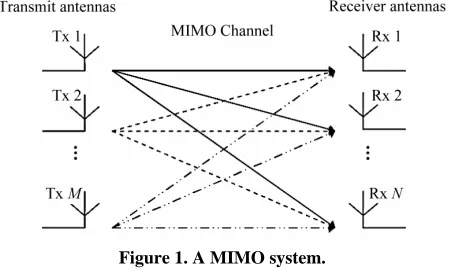
[image:2.595.312.539.86.220.2]As conventional methods like using more bandwidth or higher order modulation types are limited, new meth- ods of using thetransmission channel have to be used. Multiple antenna systems (Multiple Input, Multiple Out-put-MIMO) give a significantenhancement to data rate and channel capacity. A MIMO system employs multiple transmitter and receiver antennas for delivering parallel data streams, as illustrated in Figure 1. Since the infor- mation is transmitted through different paths, a MIMO system is capable of exploiting transmitter and receiver diversity, hence maintaining reliable communications.
Figure 1. A MIMO system.
As compared with Single-Input, Single-Output (SISO) systems, the most significant advantages of MIMO sys- tems are; a significant increase of both the system’s ca- pacity and spectral efficiency, and dramatic reduction of the effects of fading due to the increased diversity.
The quality of a wireless link can be described by three basic parameters, namely the transmission rate, the transmission range and the transmission reliability. Con- ventionally, the transmission rate may be increased by reducing the transmission range and reliability. By con- trast, the transmission range may be extended at the cost of a lower transmission rate and reliability, while the transmission reliability may be improved by reducing the transmission rate and range [18].
However, with the advent of MIMO-assisted OFDM systems, the above-mentioned three parameters may be simultaneously improved. Initial field tests of broadband wireless MIMO-OFDM communication systems have shown that an increased capacity, coverage and reliabil- ity are achievable with the aid of MIMO techniques [19].
A generic MIMO-OFDM system employing K or- thogonal frequency-domain subcarriers and having mt and nr transmit and receive antennas, respectively.
Firstly, the OFDM modulation technique is capable of coping with the highly frequency-selective, time-variant channel characteristics associated with mobile wireless communication channels, while possessing a high grade of structural flexibility for exploiting the beneficial prop- erties of MIMO architectures.
The family of space-time signal processing methods, which allow for the efficient implementation of commu- nication systems employing MIMO architectures, is commonly referred to as smart antennas.
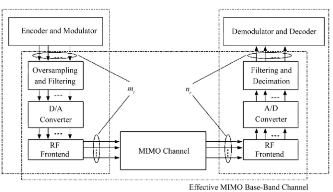
The schematic of a typical MIMO-OFDM system’s physical layer is depicted in Figure 2. The transmitter of the MIMO-OFDM system considered is typically consti- tuted by the encoder and modulator, generating a set of mt complex-valued baseband time-domain signals. The modulated baseband signals are then processed in parallel.
Figure 2. Schematic of a typical MIMO-OFDM system’s physical layer.
3. Alamouti’s
G
2STBC
then converted into an analogue passband signal using a
bank of D/A convertersand upconverted to the RF band. The system contains two transmitter antennas and one receiver antenna, a generic STBC is defined by an (n × p)-dimensional transmission matrix G, where the entries of the matrix G are linear combinations of the k input symbols x x1, , ,2 k
At the receiver side of the MIMO-OFDM transceiver, the inverse process takes place, where the set of received RF signals associated with the nr receive antenna ele- ments is amplified by the RF amplifier and downcon-
verted to an intermediate-frequency passband.
1, ,
x and their conjugates. Each symboli
x i k conveys b original information bits ac- cording to the relevant signal constellation that has M = 2b constellation points, and hence can be regarded as
information symbols. Thus, (k × b) input bits are con- veyed by each (n × p) block.
The resultant passband signals are then sampled by a bank of A/D converters, downconverted to the baseband, filtered by a matched Nyquist filter and finally decimated, in order to produce a set of discrete complex-valued baseband signals. The resultant set of discrete signals is processed by the corresponding demodulator and decoder module seen in Figure 2 where the transmitted informa- tion-carrying symbols are detected.
The G2 transmission matrix can be derived in the form of [20].
1 2 2 1
x x x x
(3) The discrete frequency-domain model of the MIMO-
OFDM system is illustrated in Figure 2 may be charac- terized as a generalization of the Single-Input Single- Output (SISO) case:
Since there are k = 2 input symbols, namely x1 and x2, the code rate of G2 is R = k/n = 1.
Two algorithms are widely used for decoding STBCs. The maximum likelihood (ML) decoding algorithm gen- erates hard-decision outputs, while the Maximum-A- Posteriori (MAP) decoding algorithm is capable of pro- viding soft outputs, which readily lend themselves to channel coding for achieving further performance im- provements.
, 1
, ,
t
m
i j ij j i ,
y n k
H n k x n k w n k (1)where and are the OFDM
symbol and subcarrier indices, respectively, while yi[n,
k], xj[n, k] and wi[n, k] denote the symbol received at the
ith receive antenna, the symbol transmitted from the jth transmit antenna and the Gaussian noise sample encoun- tered at the ith receive antenna, respectively. Furthermore, Hij[n, k] represents the complex-valued CTF coefficient
associated with the propagation link connecting the jth transmit and ith receive antennas at the kth OFDM sub- carrier and time instance n. The MIMO-OFDM system model described by (1) can be interpreted as the per- OFDM-subcarrier vector expression of
0,1,
n k0, , K1
3.1. Maximum-A-Posteriori Decoding
Bauch [21] presented a simple symbol-by-symbol MAP algorithm for decoding STBCs. According to [21], the a posteriori probability of each information symbol
1, ,
i
x i k is given by
1 2 1 2
ln , , ,
const ln , , , ln
i q
q i i
P x y y y
P y y y x P x
(4)
n k,
n k, n k,
n k
2
2 2
2
1 1 2 2 1 1, 2 2, 1 , 1 1
1 1 1
1
ln , , , const 1 ln
2
q q
j j
q j j i j
j j i
P x y y y y h y h x h x P x
(5)
2
2 2
2
2 1 2 2 1 2, 2 1, 2 , 2 2
1 1 1
1
ln , , , const 1 ln
2
q q
j j
q j j i j
j j i
P x y y y y h y h x h x P x
(6)
The corresponding a posteriori probabilities of the bits (i.e. the corresponding soft outputs) using the symbol-to-bit probability conversion of
1 2 1
1 2 1
0 , , , , ,
1 , , , , ,
i j q i i b
j
i j q i i b
j
P d P x y y y x d d d d
P d P x y y y x d d d d
0, 1, i i (7)where P(di = 0) or P(di = 1) represents the probability of
the ith bit, namely di, of the b-bit symbol being zero and
one, respectively. Then the relevant soft outputs can be forwarded to the channel decoders, which will make a hard decision to finally decode the received signals.
3.2. Channel-Coded STBC
The MAP algorithm invoked for decoding STBCs can be exploited by concatenated channel decoders for further improving the system’s performance. This paper con- catenates on the STBCs with a Turbo Convolutional (TC) code [4,22]. The STBCs can also be concatenated with a range of other channel codes, such as Convolutional Codes (CCs), Turbo Bose-Chaudhuri-Hocquenghem (TBCH) codes (a class of FEC codes), etc. The best scheme found was the half-rate TC (2,1,4) code in con- junction with the STBC G2. TTCM [23] is a more recent joint coding and modulation scheme which has a struc- ture similar to that of the family of binary turbo codes,
4. Non-Binary TCM
Convolutional codes and TCM codes are based on rings of integers modulo-M. Due to the similarities between M-PSK signal sets and the algebraic structure of rings of integers modulo-M, modulo-M ring-TCM codes are the natural linear codes for M-PSK modulation.
TCM Based on Rings of Integers
The general structure of a ring-TCM encoder suitable for M-PSK modulation, assuming that m information bits are transmitted per baud, with M = 2m+1, is shown in
Figure 3. This ring-TCM encoder works as follows [24]:
First, m + 1 information bits, bi, are mapped into a
modulo-M symbol, aj, according to a mapping func-
tion f (for instance, f can be a Gray mapping func- tion).
Next, m modulo-M aj symbols are introduced into a
linear multi-level convolutional encoder (MCE), which generates m + 1 modulo-M coded symbols, xk. Finally, each one of these coded symbols xk is associ-
ated with a signal of the M-PSK signal set and is sent to the channel.
As a total of m + 1 modulo-M coded symbols xk are
transmitted per single trellis branch, ring-TCM codes can be considered as 2(m + 1)-dimensional TCM codes.
5. Rings of Integers
If the two binary operations “+” and “·” are allowed then a ring can be defined. A ring must have the following conditions; associativity, distributivity, and commutativ- ity under addition. The ring is called a commutative ring if it also has commutativity under multiplication. If the ring has a multiplicative identity 1 then it is called a ring with identity. An example of a ring is the ring of integers
q under modulo-q addition and multiplication, where q
is the cardinality of the ring. For example, is de- fined as {0, 1, 2, 3}.
4
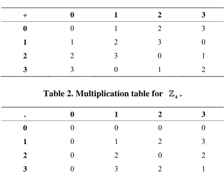
It is easy to see that the elements obey the three defini- tions of a ring. Also, all the elements commute under multiplication and the multiplicative identity element 1 is present, meaning that 4 is a commutative ring with identity. Tables 1 and 2 show the addition and multipli- cation tables respectively of the ring of integers
4 0,1, 2,3
[25].
The set of all polynomials with coefficients defined in
q forms a ring under the addition and multiplication
Figure 3. General structure of a ring-TCM encoder suitable for M-PSK modulation.
Table 1. Addition table for 4.
+ 0 1 2 3
0 0 1 2 3
1 1 2 3 0
2 2 3 0 1
[image:5.595.307.537.136.279.2]3 3 0 1 2
Table 2. Multiplication table for 4.
. 0 1 2 3
0 0 0 0 0
1 0 1 2 3
2 0 2 0 2
3 0 3 2 1
6. A 4-State Ring-TCM Code Defined over 4
A good 4-state ring-TCM code over 4 is shown in Figure 4 and this would be used in this research work [24].
Where each of the input and output of Figure 4 rep- resent the elements of the ring of integers modulo-4, , and all addition arithmetic operations satisfy the properties of the ring of integers modulo-4 addition. The delay block represents the constraint length (number of memory elements, i.e., in this case there is only one memory element).
4 0,1, 2,3
Yaletharatalhussein Decoding Algorithm
The Yaletharatalhussein non-binary decoding algorithm is proposed in this paper for decoding non-binary convo- lutional codes. Convolutional codes differ from block codes in that a block code takes a fixed message length and encodes it, whereas a convolutional code can encode a continuous stream of data, and a hard-decision decod- ing can easily be realized using the Yaletharatalhus- seinalgorithm.The decoder for the non-binary convolu- tional code finds the most probable sequence of data bits
given the received sequence y: ˆ
u
ˆ arg max u u p u
y
(8)
where y is the set of code symbols c observed through noise. The above equation can be solved using the Yaletharatalhussein algorithm, explained later.
The principle states that creating a state vector con-
X2
X1
3
1
2
Delay
Output Input
Figure 4. A 4-state ring-TCM encoder.
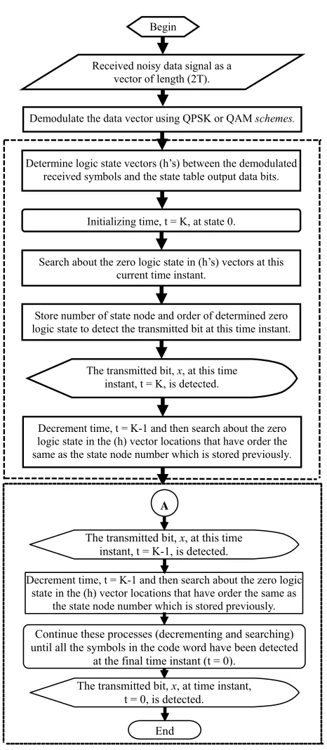
taining binary logic states, which represents the similari- ties and differences between y symbols associated with each u bits at the current time instant, and then searching for a minimum logic state in this vector to determine the state node number with its order bit for using in the next time instant of searching strategy method, in one hand, and for recovering the transmitted code word in the other hand. In this case, the decoding method is independent on the trellis diagram representing the non-binary con- volutional encoder. The 4-ring-TCM demodulator and decoder-based Yaletharatalhussein decoding algorithm can be represented by a flowchart as shown in Figure 5. The flow chart inside the dashed lines represents the Yaletharatalhussein decoding algorithm.
7.
4-Ring-TCM Assisted STBC-OFDM
System Overview
4
-Ring-TCM channel code can be combined with the G2 STBC to improve the system performance. Figure 6 shows a schematic of the 4-ring-TCM-assisted G2 STBC-OFDM system. The source information bits are first encoded and modulated by the 4-ring-TCM en- coder followed by the space-time encoder, the STBC employed was the G2 code, which invokes two transmit- ter antennas, and the two space-time-coded samples are mapped to two consecutive OFDM subcarriers and OFDM modulated.
The OFDM symbols are then transmitted via the multi-path fading channel, and the received noise-con- taminated symbols are forwarded to the OFDM demodu- lator. The recovered signal is then space-time soft de- coded and the soft outputs are fed to the 4-ring-TCM- decoder which used the Yaletharatalhussein algorithm for recovering the most likely transmitted information bits.
[image:5.595.56.287.168.349.2]Received noisy data signal as a vector of length (2T).
Demodulate the data vector using QPSK or QAM schemes.
Determine logic state vectors (h’s) between the demodulated received symbols and the state table output data bits.
Initializing time, t = K, at state 0.
Search about the zero logic state in (h’s) vectors at this current time instant.
Store number of state node and order of determined zero logic state to detect the transmitted bit at this time instant.
Decrement time, t = K-1 and then search about the zero logic state in the (h) vector locations that have order the same as the state node number which is stored previously.
The transmitted bit, x, at this time instant, t = K, is detected.
Decrement time, t = K-1 and then search about the zero logic state in the (h) vector locations that have order the same as
the state node number which is stored previously.
Continue these processes (decrementing and searching) until all the symbols in the code word have been detected
at the final time instant (t = 0).
End
The transmitted bit, x, at time instant, t = 0, is detected.
The transmitted bit, x, at this time instant, t = K-1, is detected.
[image:6.595.56.289.74.608.2]A
Figure 5. Flow chart of the -ring-TCM demodulator- decoder-based Yaletharatalhussein decoding algorithm.
4
8. Simulation Results
The performance of the 4-Ring-TCM-PAM-based Ya- letharatalhussein decoding algorithm-assisted G2 STBC- OFDM system is studied when communicating over Rayleigh fading channel. Specifically, the short wireless asynchronous transfer mode channel impulse response [26] is considered. The simulation results can be shown
Sink G2 STBC DemodulatorOFDM
Soft Decoder
4
-Ring-TCM Decoder-based Yaletharatalhussein
Algorithm
Channel
● ●
●●●
[image:6.595.307.539.85.197.2]●●●
Figure 6. Schematic diagram of the proposed -ring- TCM-assisted G2 STBC-OFDM system.
4
in Figure 7, where the (BER) versus
E Nb 0
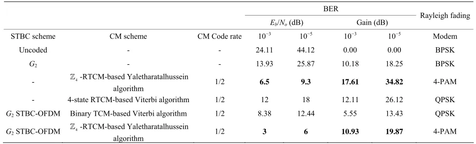
perform- ance is displayed in each figure including the number of symbols (N).For the sake of comparison with the proposed non- binary scheme in this paper, the work [26] was studied the performance of the binary TCM-QPSK-assistedG2 STBC-OFDM system and can be shown in Figure 8, and the performance of a 4-state ring-TCM code on urban MIMO fading channel was presented by the work [27], and can be shown in Figure 9. All the mentioned pervi- ous TCM codes were transparent, and decoded using the soft-decision Viterbi algorithm [28,29]. The perform- ances of the 4-Ring-TCM scheme-based Yaletharatal- hussein decoding algorithm, 4-Ring-TCM-based Yale- tharatalhussein decoding algorithm-assisted G2 STBC- OFDM scheme, and the presented schemes of works [26] and [27] can be summarized in Table 3, where the cod- ing gains are defined as the (Eb/No) difference, expressed
in decibels, at BERs of 10−5 and 10−3 between the various channel coding assisted STBC-OFDM systems and the uncoded single transmitter system having the same effec- tive throughput.
The performance of the best scheme in Table 3 is (printed in bold), since the performance comparison shows that the 4-ring-TCM-PAM scheme-based Yale- tharatalhussein algorithm outperforms both the 4-ring- TCM-QAM scheme and the 4-ring-TCM-PSK scheme- based Yaletharatalhussein algorithm, since this scheme is provided that the gains in (Eb/No) are (17.61 dB) and
(34.82 dB) at the BERs of 10−3 and 10−5 respectively.
Also, the 4-ring-TCM-PAM scheme-based Yale- tharatalhussein algorithm outperforms the 4-state ring- TCM-based Viterbi algorithm by the gains (8.7 dB and 5.5 dB) at the BERs (10−3 and 10−5) respectively.
For the G2 STBC-OFDM concatenated systems, the 4 -Ring-TCM-4-PAM-based Yaletharatalhussein de- coding algorithm-assisted G2 STBC-OFDM scheme out- performs the binary TCM-based Viterbi algorithm-as- sisted G2 STBC-OFDM scheme by the gains; (10.93 dB and 19.87 dB) at the BERs (10−3 and 10−5) respectively.
[image:7.595.63.530.84.477.2]
Figure 7. The (BER) versus (Eb/No) performance of the -ring-TCM-based Yaletharatalhussein decoding algorithm-as-
sisted G2 STBC-OFDM system.
4
Figure 9. The (BER) versus (Eb/No) performance of a 4-state
[image:7.595.324.525.519.696.2]ring-TCM code on the pedestrian MIMO fading channel [28].
Figure 8. The (BER) versus (Eb/No) performance of a binary
[image:7.595.61.286.521.703.2]BER
Eb/No (dB) Gain (dB)
Rayleigh fading
STBC scheme CM scheme CM Code rate 10−3 10−5 10−3 10−5 Modem
Uncoded - - 24.11 44.12 0.00 0.00 BPSK
G2 - - 13.93 25.87 10.18 18.25 BPSK
- 4-RTCM-based Yaletharatalhussein
algorithm 1/2 6.5 9.3 17.61 34.82 4-PAM
- 4-state RTCM-based Viterbi algorithm 1/2 12 18 12.11 26.12 QPSK
G2 STBC-OFDM Binary TCM-based Viterbi algorithm 1/2 8.38 12.44 5.55 13.43 QPSK
G2 STBC-OFDM 4-RTCM-based Yaletharatalhussein
algorithm 1/2 3 6 10.93 19.87 4-PAM
The performance of a 4-state ring-TCM code on the pedestrian MIMO fading channel which is shown in Figure 9 performs poorly with an error floor and thus, the 4 -Ring-TCM-4-PAM-based Yaletharatalhussein decoding algorithm-assisted G2 STBC-OFDM scheme is the best scheme among the evaluated binary and the non- binary schemes.
The effective throughput of the -ring-TCM-PAM can be expressed by: p
log2R p M
(9)where R, is the code rate, p, and M, is the modula- tion order. Since, for R = 1/2, p = 4, and M = 4, then η = (2) bits/s/Hz.
9. Conclusions and Future Works
A novel non-binary decoding method, is called Yale- tharatalhussein decoding algorithm that is proposed for decoding non-binary convolutional and TCM codes, which is independent on the trellis diagram representing the non-binary convolutional encoder, as in Viterbi algo- rithm.
The Yaletharatalhussein algorithm employed a hard- decision decoding, which needed less computational complexity over the soft-decision MLD of Viterbi algo- rithm. In Yaletharatalhussein algorithm, the code words are detected instantaneously through searching in the developed state vectors, while in Viterbi algorithm, the hamming distances between numbers and transition met- rics are calculated and a comparison between competitive accumulated metrics is done for every state of the trellis diagram.
It is shown that the idea of TCM has been extended for symbols defined over rings of integers q and that in- creased the bandwidth efficiency by a factor of
q over the binary TCM code. The use of non-binary TCM led to reduction in the effective input block length, since m bits of binary information correspond to one non-bi- nary symbol for q = 2m, and thus non-binary system can
be used with a high number of symbols.
The Yaletharatalhussein decoding algorithm achieved high spectral efficiency and good error performance of non-binary schemes-assisted G2 STBC-OFDM systems, thus it can satisfy requirements of the 4G wireless sys- tems over the non-binary TTCM systems due to very high computational complexity.
A future work can be done by studying the perform- ance of the Yaletharatalhussein decoding algorithm for non-binary schemes that assisted each type of space-time coding, such as space-time trellis coding (STTC)-aided OFDM systems, and also, by studying the performance with each number of transmitters and receivers.
REFERENCES
[1] H. H. Wang, L. P. Kondi, A. Luthra and S. Ci, “4G Wire- less Vedio Communications,” John Wiley & Sons Ltd., UK, 2009.
[2] S. Hara and R. Prasad, “Multicarrier Techniques for 4G Mobile Communications,” Artech House, Boston, 2003. [3] L. Hanzo and B. Choi, “Near-Instantaneously Adaptive
HSDPA-Style OFDM and MC-CDMA Transceivers for WiFi, WiMAX and Next-Generation Systems,” Proceed- ings of the IEEE, Vol. 95, No. 12, 2007, pp. 2368-2392. http://dx.doi.org/10.1109/JPROC.2007.904445
[4] K. Fazel and S. Kaiser, “Multi-Carrier and Spread Spec-trum Systems from OFDM and MC-CDMA to LTE and WiMAX. John Wiley and Sons, Ltd., 2008.
http://dx.doi.org/10.1002/9780470714249
[5] C. Berrou and A. Glavieux, “Near Optimum Error Cor- recting Coding and Decoding: Turbo Codes,” IEEE Transactions on Communications, Vol. 44, No. 10, 1996, pp. 1261-1271. http://dx.doi.org/10.1109/26.539767 [6] R. Gallager, “Low Density Parity Check Codes,” IEEE
Transactions on Information Theory, Vol. 8, No. 1, 1962, pp. 21-28. http://dx.doi.org/10.1109/TIT.1962.1057683 [7] D. J. C. Mackay and R. M. Neal, “Near Shannon Limit
[image:8.595.53.541.101.249.2][8] B. Lu, X. Wang and K. R. Narayanan, “LDPC-Based Space-Time Coded OFDM Systems over Correlated Fad- ing Channels: Performance Analysis and Receiver De- sign,” Proceedings of the 2001 IEEE International Sym- posium on Information Theory, Washington DC, 24-29 June 2001, p. 313.
[9] “Using MIMO-OFDM Technology to Boost Wireless LAN Performance Today,” White Paper, Datacomm Re- search Company, St. Louis, USA, 2005.
[10] H. Sampath, S. Talwar, J. Tellado, V. Erceg and A. J. Paulraj, “A Fourth-Generation MIMO-OFDM Broadband Wireless System: Design, Performance, and field Trial Results,” IEEE Communications Magazine, Vol. 40, No. 9, 2002, pp. 143-149.
http://dx.doi.org/10.1109/MCOM.2002.1031841
[11] L. R. Bahl, J. Cocke, F. Jelinek and J. Raviv, “Optimal Decoding of Linear Codes for Minimizing Symbol Error Rate,” IEEE Transactions on Information Theory, Vol. 20, No. 2, 1974, pp. 284-287.
http://dx.doi.org/10.1109/TIT.1974.1055186
[12] J. Jayakumari, “MIMO-OFDM for 4G Wireless Sys- tems,” International Journal of Engineering Science and Technology, Vol. 2, No. 7, 2010, pp. 2886-2889.
[13] L. Hanzo, Y. (Jos) Akhtman, L. Wang and M. Jiang, “MIMO-OFDM for LTE, Wi-Fi and WiMAX Coherent versus Non-Coherent and Cooperative Turbo-Transceiv- ers,” John Wiley & Sons Ltd., UK, 2011.
[14] Institute of Electrical and Electronics Engineers, “IEEE Standard 802.11: Wireless LAN Medium Access Control (MAC) and Physical Layer (PHY) Specifications,” 18 November 1997.
[15] L. Lin, L. J. Cimini Jr. and C.-I. Chuang, “Comparison of Convolutional and Turbo Codes for OFDM with Antenna Diversity in High-Bit-Rate Wireless Applications,” IEEE Communications Letters, Vol. 4, No. 9, 2000, pp. 277- 279.
[16] WiMAX Forum, “WiMAX Forum WiMAX Technology Forecast (2007-2012),” June 2008.
http://www.wimaxforum.org/technology/downloads/ [17] A. R. S. Bahai, B. R. Saltzberg and M. Ergen, “Multi-
Carrier Digital Communications Theory and Applications of OFDM,” 2nd Edition, Springer Science + Business Media, Inc., Boston, 2004.
[18] European Telecommunications Standards Institute, “Digi- tal Video Broadcasting (DVB); Framing Structure, Chan- nel Coding and Modulation for Digital Terrestrial Televi- sion (DVB-T),” ETSI ETS 300 744, March 1997.
[19] European Telecommunications Standards Institute, “Ra- dio Equipment and Systems (RES); High Performance Radio Local Area Network (HIPERLAN) Type 1; Func- tional Specification,” ETSI ETS 300 652, October 1996. [20] G. Chen and X. Dong, “From Chaos to Order: Method-
ologies, Perspectives and Applications,” World Scientific Publishing Co. Pte. Ltd., Singapore, 1998, pp. 598-614. [21] G. Bauch, “Concatenation of Space-Time Block Codes
and Turbo-TCM,” Proceedings of IEEE International Conference on Communications, Vancouver, 6-10 June 1999, pp. 1202-1206.
[22] C. Berrou, A. Glavieux and P. Thitimajshima, “Near Shannon Limit Error-Correcting Coding and Decoding: Turbo Codes,” Proceedings of the International Confer- ence on Communications, Geneva, 23-26 May 1993, pp. 1064-1070.
[23] P. Robertson and T. Worz, “Bandwidth Efficient Turbo Trellis-Coded Modulation Using Punctured Component Codes,” IEEE Journal on Selected Areas in Communica- tions, Vol. 16, No. 2, 1998, pp. 206-218.
http://dx.doi.org/10.1109/49.661109
[24] R. Carrasco, F. Lopez and P. Farrell, “Ring-TCM for M-PSK Modulation: AWGN Channels and DSP Imple- mentation,” IEE Proceedings—Communications, Vol. 143, No. 5, 1996, pp. 273-280.
[25] E. H. Connel, “Elements of Abstract and Linear Algebra,” Coral Gables, 2004.
[26] L. Hanzo, T. H. Liew and B. L. Yeap, “Turbo Coding, Turbo Equalisation and Space-Time Coding,” IEEE Press and John Wiley & Sons, Ltd., Chichester, 2002. http://www-mobile.ecs.soton.ac.uk
[27] A. J. Paulraj, D. A. Gore, R. U. Nabar and H. Bolcskei, “An Overview of MIMO Communications—A Key to Gigabit Wireless,” Proceedings of the IEEE, Vol. 92, No. 2, 2004, pp. 198-218.
http://dx.doi.org/10.1109/JPROC.2003.821915
[28] A. J. Viterbi, “Error Bounds for Convolutional Codes and Asymptotically Optimum Decoding Algorithm,” IEEE Transactions on Information Theory, Vol. 13, No. 2, 1967, pp. 260-269. http://dx.doi.org/10.1109/TIT.1967.1054010 [29] G. D. Forney, “The Viterbi Algorithm,” Proceedings of
![Figure 9. The (BER) versus (Eb/No) performance of a 4-state ring-TCM code on the pedestrian MIMO fading channel [28]](https://thumb-us.123doks.com/thumbv2/123dok_us/7914117.746165/7.595.63.530.84.477/figure-versus-performance-state-pedestrian-mimo-fading-channel.webp)