The Jupiter Receiver
Abhishek Vernekar
1, Shubham Yedekar
2, Omkar Chikhalwadkar
31,2,3 Department of Electronics and Telecommunication Engineering, KIT’s College of Engineering ,Kolhapur, India
---***---Abstract -
We study both Jupiter and solar radio emissions to better understand their magnetic fields and their plasma [charged particle] environment. Studying other planets always helps us better understand the Earth, and this is true when we study Jupiter's radio emission. Earth also emits radio waves by similar processes, so we can better understand this process by listening to Jupiter from both ground-based and space-based radio antennas. Not only can we learn about why the radio waves are created and how they move through space, we can also learn about the interior of Jupiter and about Jupiter's moons. Radio waves are generated because the planet has a magnetic field. This magnetic field originates deep in the interior of the planet, and the overall strength of the magnetic field directly affects the type of radio emission emitted by the planet. This helps us with the theory of how the magnetic field is created in the interior, and in determining the composition of the various interior layers.Key Words: Magnetic, antennas.
1. INTRODUCTION
Natural radio emissions from Jupiter or from Sun are detected by using a dual dipole array as an antenna and with a sensitive receiver. The RF voltage developed at the antenna terminals is amplified with the RF amplifier and converted into audio frequencies using a mixer. The audio signal thus generated is recorded on PC through a sound card in ‘wav’ format. Also a strip-chart recorder software is available to generate the strip-chart of data coming through sound card. The antenna and receiver discussed is based on the design given by NASA Radio Jove Program.
Particles spiraling along field lines in Jupiter's magnetosphere radiate electromagnetic energy as cyclotron and synchrotron emissions. These radiations are generally quite directional, leaving the vicinity of the planet in the form of narrow radio beams. At least seven different source have been identified. Some of these sources correlate with certain rotational alignments of the Jovian magnetic field while others are associated with both the alignment of the magnetic field and the position of the moon Io as seen from the Earth.
The requirements of the receiver for Jupiter observations are discussed. So receivercharacteristics required for Jupiter are defined in terms of operating frequency, Sensitivity, Gain, Bandwidth, Dynamic range etc.
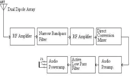
1.1 Block Diagram
Fig -1: Guru Receiver
The RF amp used here is single stage RF amp using N-channel JFET(J310). Mixer used is low power VHF monolithic double-balanced mixer. Audio amplifier used here is designed for amplification of weak signals from tape head. Low pass filter band limits the mixer output to audio frequencies up to 3.3 KHz. Power amplifier is used to amplify the audio signals to sufficient level so that it can drive the speaker.
The RF amplifier used in high frequency operation will be designed as its bandwidth is much greater than that of common source amplifier. The RF amplifier will be designed using a BJT and a tank circuit. A Narrow Band-pass Filter having bandwidth of 0.5 MHz is to designed and centered at 20.1 MHz. The BPF must have of a Quality Factor of 40 and to be designed up to 5th order.
A Mixer is to be designed for Jupiter Receiver the Local Oscillator is tuned to 20.1Mhz so that mixer can down convert the signals to audio frequency range. Audio preamplifier is designed for amplification for weak signals from tape head. A Low Pass Filter band limits the mixer output to audio frequencies up to 3.3 KHz. Also to have less loss and sharp cutoff the active filter is used. The filter is of 5th order.
2. THEORY OF RECEIVER
The requirements of the receiver for Jupiter observations are discussed.
[image:1.595.323.536.194.324.2]
2.1 Frequencies For Observations
The best suitable frequencies are in between 18 to 22MHz, as the chances of getting emissions are more. In practice 18.7 MHz, 20.1MHz, 22.3 MHz are common. The frequencies above 30 MHz are not suitable because of less strength.
2.2 Sensitivity
Whenever we receive any signal we receive it against the noise. Noise consists of the noise generated inside the receiver as well as the noise coming from the antenna. The sensitivity of the receiver required can be calculated as follows: - Assuming the signal strength of Jupiter around 10^5Jy, the power at antenna terminals can be calculated as Power at antenna terminals = Flux density X Aperture area X receiver bandwidth
Here the receiver bandwidth is assumed to be 3.3 KHz. Thus converting power into dBm, we get the receiver sensitivity as -124.4dBm. Sensitivity = -125dBm.
2.3 Gain
Since we are going to down covert the Jupiter signal at 20MHz to audio frequencies, the signal should be amplified to such a level so that it can drive a headphone i.e. to have audible signal.
So to achieve the audible signal the gain required is Av=110db.
2.4. Bandwidth
Usually the signals are band limited to 3-5 KHz. The bandwidth of the receiver is determined by the bandwidth of the low pass filter after mixer. Typically it is selected as 3.3KHz same as that of voice signals. In case of Guru Receiver which is direct conversion type the image frequency is also in the pass-band of the low pass filter thus giving the effective bandwidth of 6.6 KHz.
3. Components of Receiver
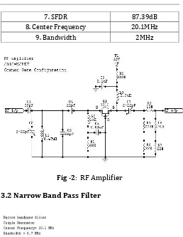
3.1 The RF Amplifier
The RF Amplifier is tuned to 20.1 MHz
N-channel JFET(J310) will be used in common gate configuration
1. Gain 9dB
2. VSWR 1.1
3. Noise Figure 3.195dB
4. Noise Temperature 315.17 Kelvin 5.Minimum Discernible signal (BW=3.3KHz)
6. 1dB compression point -12dBm
7. SFDR 87.39dB
8. Center Frequency 20.1MHz
9. Bandwidth 2MHz
Fig -2: RF Amplifier
3.2 Narrow Band Pass Filter
Fig -3: Narrow Bandpass Filter
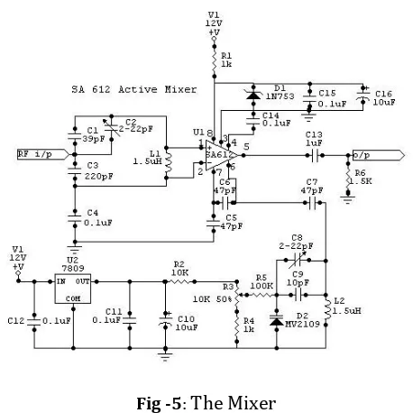
[image:2.595.307.565.65.398.2]3.3 The Mixer
Fig -5: The Mixer
1.The Mixer used in this receiver is Philips SA612.
2.The SA612A is a low-power VHF monolithic double-balanced mixer with on-board oscillator and voltage regulator.
3.For Guru receiver the LO is tuned to 20.1MHz so that mixer can down convert the signals to audio frequency range.
3.4 Low Pass Filter
Fig -6:Low Pass Filter
1. Low pass filter band limits the mixer o/p to audio frequencies up to 3.3 KHz.
2. 5th order low pass sallen-key configuration filter.
3. The filter is 60db down at 10khz and having 3db cut off of 3.3 KHz. The response of the filter is selected as chebyshev to have sharp cutoff.
3.5 Audio Preamplifier
Fig -7: Audio Preamplifier
1.Low noise audio preamplifier LA3161 which is designed for amplification of weak signals
2.Loop voltage gain of 35dB.
3.Equivalent i/p noise voltage of 1.2microV
3.6 Audio Power-Amplifier
Fig -8: Audio Power-Amplifier
1. To amplify the audio signal to sufficient level so that it can drive the speaker
2. Audio o/p drives the headphone while other is used for recording the data in ‘wav’ format through the sound card
1. Quality factor(Q) 40
2. Bandwidth centered at 20.1Mhz 0.5MHz desirable 3. Pass band
[image:3.595.47.276.104.333.2] [image:3.595.328.556.193.359.2] [image:3.595.40.286.493.653.2] [image:3.595.328.560.497.666.2]4. Antenna Construction
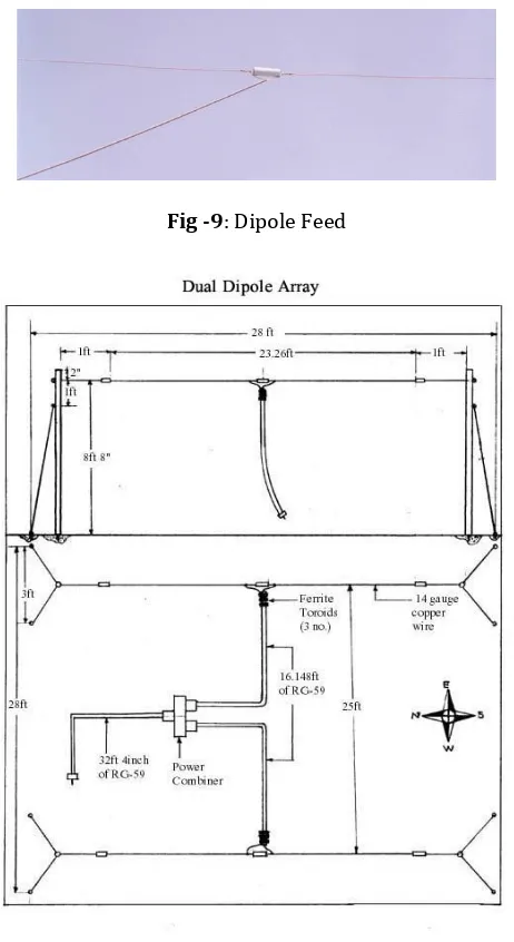
This antenna is an array of two half-wave dipoles separated by a distance of half wavelength. And are maintained at a height of quarter wavelength. The dipoles are North-South aligned. (They can be aligned to East-West also depending upon requirement.) Signals from each single dipole antenna are added with a power combiner via two pieces of coaxial cable which are half wavelength long. (I am using Coaxial cable of RG-58 type of 50 ohms impedance.) The output of the power combiner is delivered to the receiver by another section of coaxial transmission line full wavelength long.
Fig -9: Dipole Feed
Fig -10: Antenna Dimensions
4.1 Testing the Receiver
Before making the observation of Jupiter it is a good idea to set up the antenna and receiver to confirm that everything is working properly. For this test we set up the dual dipole array. With no antenna connected, we may hear a slight hissing sound in the headphones (or loudspeaker if we are using an amplified speaker). With the antenna connected, the
static sound should increase significantly. (There is usually a loud crackling sound as the antenna connector is being screwed on). The Jove receiver is connected to a computer running Radio-SkyPipe you should see a significant increase in the background trace when the antenna is connected. The trace should rise sharply as we tune across stations. The SkyPipe trace is normally set at a level of about 1000 on the vertical scale. This level is set using the receiver volume control and the software record volume control found on your computer. With the antenna connected we hear background static (this is galactic background radiation - caused by relativistic electrons spiralling in our galactic magnetic field). As we tune the receiver we may hear stations. When listening for Jupiter or the Sun we should tune to a clear frequency between the stations.
[image:4.595.46.277.232.655.2]
We may also hear pops and snaps due to distant lightning. (If there is nearby lightning don’t set up antenna and receiver). If we do not hear a significant noise increase when connected the antenna either there is a short or open circuit in the antenna wiring or the receiver is not working correctly. We can trouble-shoot the antenna by hooking up the individual dipoles directly to the receiver (bypassing the power combiner). If either dipole individually produces the desired receiver noise increase then the problem must lie with the other dipole, the power combiner, or the lead-in coax. If you are unable to obtain the noise increase with either dipole individually, or connected together as a pair, then the problem must lie with the receiver (or its power supply or some audio cabling, perhaps between the receiver and the computer or audio amplifier). The noise that you hear with the antenna connected should have a steady hissing static sound (except for stations and an occasional static pop or crash).
Fig -11: Radio-SkyPipe Observations
5. CONCLUSIONS
1. Jupiter Receiver Is A Fundamentally New Method Of Detecting Rotation Of Planets.
2. Relative Position Of Jupiter And Earth Can Be Detected.
[image:4.595.318.549.492.629.2]REFERENCES
[1] http://www-ssc.igpp.ucla.edu/IJW/h
[2] http://www.europhysicsnews.com/full/21/article1/art
icle1.html
[3] http://wwwssc.igpp.ucla.edu/personnel/russell/papers
/Io_Jovian/
[4] http://wwwssc.igpp.ucla.edu/personnel/russell/papers
/waves_fluc_jov/
[5]