A Global Integrated Artificial Potential Field/Virtual Obstacles Path
Planning Algorithm for Multi-Robot System Applications
Abdelrahman M. Hassan
1, Catherine M. Elias
1, Omar M. Shehata
1and Elsayed I. Morgan
11
Multi-Robot Systems (MRS) Research Group, German University in Cairo, 5th Settlement New Cairo, 11432,
Cairo, Egypt
---***---Abstract -
In this paper, a global off-line path planningapproach is implemented using an energy-based approach Artificial Potential Field (APF) for Multi-Robot Systems (MRSs). A 3-D potential map is created by using simplified potential functions. Both attraction forces between the robots and the goal, and repulsion forces to repel the robots from the obstacles and each other, are calculated to generate the 3-D map. The local minima problem is handled in this paper using the Virtual Obstacles (VOs) approach. The robot path is generated starting from the robot initial position to the goal based on the generated 3D potential map to be followed by the mobile robots. All simulations are done using MATLab and Virtual Robot Experimental Platform (V-REP). On the MATLab side, the APF controller is implemented to build the map and generate robots paths. The robots are controlled to track the paths and visualized in the V-REP environment.
Key Words: Multi-Robot Systems, Path Planning, Artificial Potential Field, V-REP, Local Minima, Virtual Obstacles
1. INTRODUCTION
Nowadays, Multi-Robot Systems (MRSs) are one of the most growing areas in Robotics. As result of the technology in our life and the demand on robots in many tasks and applications, the challenges of MRS are increasing in a rapid way every day. Single-Robot Systems (SRSs) tasks are being more complex and expensive by time that is why MRSs are a necessity. MRSs added more applications and challenges to the Robotics field such as pollution monitoring, surveillance of buildings [1], warehouse management, forest fire detection and more applications. They even replaced SRSs in many applications as the robustness and reliability can be increased with more than one single robot [2]. Area coverage and exploration [3] is one of the main applications in robotics field in general. It was first developed with SRSs. Simultaneous Localization and Mapping (SLAM) is an application for robots that they generate a map for the surrounding environment by locating the obstacles and represent them in a way that allow the robots to navigate any uncovered areas [4]. There is advantage in Multi-Robot team that will improve the positioning accuracy, as every robot will be scanning or mapping specific area. By integrating all the maps, there will be a main map for the whole place [5]. Search and Rescue is another challenge of
MRSs. First, the robot search for an object with specific characteristics. Then when any robot finds this object, it sends signals for all other robots. All robots stand around the object and they carry it to a specific goal. This can only be done through a team of robots, since one robot cannot handle the object if it is big and heavy [6]. Task Allocation application is used commonly in robots rescue missions, where the group of robots has a set of tasks or goals that must be done. Some tasks need more than one robot and some tasks can be handled by only one. In order to organize these tasks for the robots team, the Task allocation problem is handled [7], [8].
2. PATH PLANNING
Path Planning is the controller of the robot motion, so it is the most essential part of the robot program. It is the determination of a free path starting from the robot position to the targeted goal. The robot environment consists of three modules, the robot itself, the goal and the obstacles in between. Path Planning can be divided in two main categories, global path planning and local path planning. In global path planning, the environment of the robot is already known with all obstacles and their locations. The terrain is static that is why a map can be generated with the path for the robot. On the other hand, in local path planning, the environment is unknown for the robot and can be dynamic. In that case, the robot must gather information about the environment in real time, and then update its control laws to achieve its goal [9].
Artificial Potential Field (APF) is one of the classical approaches that are used to implement the path-planning controller. In 1986, Khatib [21] introduced the first APF approach for real-time obstacle avoidance problem for manipulators and multi-robot systems. Rimon and Koditschek adopted in 1992 [10] the APF in as an approach for exact robot motion planning and control using navigation functions instead of the potential functions to solve the local minima problem. Then in 2000, Ge and Cui [11] described the problem of non-reachable goals with obstacle nearby when using APF using a new repulsive function to solve it. As an extension for their work, the potential field approach was proposed as obstacle avoidance methods for robots in dynamic environments in [12] in 2002. In addition, in 2005, the authors used queues and formation vertices, besides the
APF for controlling the formation of group of robots to improve the flexibility of the robot formation and in the same time, the group can avoid the obstacles [13]. Another paper conducted by Hsieh, Kumar and Chaimowicz in 2008 proposed a decentralized controller for shape generation with swarm of mobile robots [14]. A paper conducted by Nagy in 2009 to implement a controller for multi-agent system using Genetic Algorithm (GA) to build a potential field for unknown environments [15]. Saez-Pons, Alboul et. al. in 2010 [16] used the APF for controlling the group formation of multi-robot system called (GUARDIANS). Then in 2012 [17], Valbuena and Tanner suggested new control for differential mobile robot navigation using APF based on navigation functions, then a transformation for the mathematical results was introduced to obtain real-time velocities to be tested on real robot. Also, Hsieh, Kumar and Chaimowicz in 2008 [18] proposed an APF algorithm for mobile manipulator control using simplified potential functions. In [19] Rajvanshi, Islamused et. al. used the APF for controlling mobile robots in both static and dynamic environments in 2015 using Artificial Goals approach to solve the local minima problem. And in the same year, Ahmed, Abdalla and Abed [20] proposed Particle Swarm Optimization (PSO) method to modify the potential field method used, in order to solve the problem of local minima and optimize the path resulted by it.
In this Paper, an offline (global) path-planning algorithm based on a modified APF approach is proposed for the control of multi robot system in any cluttered static environment. The local minima problem is handled using the virtual obstacle approach. The modification of the APF is for generating the shortest path for the robots. Simulations are used to verify the proposed approach using MATLab and V-REP simulators.
The rest of the paper is organized as follows: Section 3 introduces the APF graphically, mathematically, and introduces the local minima problem. Section 4 has the mathematical model and introduces the V-REP environment. Section 5 has the simulations results. Section 6 is the conclusion, and finally, Section 7 suggests future recommendations for further researches.
3. ARTIFITIAL POTENTIAL FIELD
The Artificial Potential Field (APF) is one of the classical path planning approaches that is used in robotics. It can be used in global and local path planning. It can be also used in dynamic or static environments. The concept about APF is to find a mathematical function to represent the energy of the system based on the idea of physical rules in potential fields. Potential functions assume the existence of repulsive and attractive forces acting on the robot in its world. Using both repulsive and attractive forces, a path for the robot can be created to its destination. The attractive force is generated between the robot and the goal. It is responsible for attracting the robot to the goal. The repulsive force is between the robot and the obstacles. Its main function is for avoiding them. Both
forces are generated by mathematical functions that are represented graphically by high and low areas in the robot space.
The general APF equation as [11], [15], [19] and [21] introduced is as follows
) ( ) ( )
(q U q U q
U att rep (1)
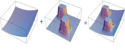
[image:2.595.309.558.253.353.2]where Uatt(q) is the attractive is function, and Urep(q)is the repulsion function. By summing both functions together, the total potential function is generated to be used in the control of the robots.
Fig -1: Total Potential Function
3.1 Attraction Potential Function
The Attractive Potential Function is divided in two terms, conical potential and Quadratic potential. The conical potential is used when the robot is far away from the goal. On the other hand, the quadratic potential is used when the robot is near the goal. The reference that will define whether the robot is far or near is the term *
goal
d
. * * 2 * * 2 ) , ( ) , ( ) ( 2 1 ) , ( ) , ( 2 1 ) ( goal goal goal goal goal goal goal goal att d q q d if d q q d if d q q d d q q d q U (2)whereqis the position variable, d(q,qgoal)is the distance function, and is the scaling factor.
This function is representing the potential that affect the robot while the force that will drive the robot to reach the goal will be generated from the negative gradient of this function.
) ( )
(q U q
Fatt att (3)
As * * * ) , ( ) , ( ) ( ) ( ) ( ) ( goal goal goal goal goal goal goal goal att d q q d if d q q d if q q d q q d q q q U (4)
Moreover, in other works, Hargas et. al. [18] used another simplified version of the potential function. This equation
has the position of the robot and the goal; X and Ycoordinates, as the equation parameters.
] ) ( ) [( 2 1 ) ,
( a Fin 2 Fin 2
att x y K x x y y
U (5)
where x and yare the coordinates of the current position
of the robot, xFinand yFinare the goal coordinates, and Ka is the scaling factor.
And the attractive force will be defined as
) ( ) , ( ) ( ) , ( ) , ( ) , ( Fin a att ya Fin a att xa att y y K y U y x f x x K x U y x f y x y x U (6)
where fxa(x,y), fya(x,y)are the attractive forces in the x and y directions respectively.
3.2 Repulsive Potential Function
There is always one goal at a time for the robot but the obstacles are more than one. That is why the repulsive potential function consists of all the repulsive fields of every obstacle exists in the environment. Every obstacle has a specific limited region that has a repulsive field, so that when the robot comes in that region, it will be repelled from that obstacle. The term that would define the region for every obstacle is *
Q . And the repulsive field for only one obstacle is * * 2 * ) ( ) ( 0 ) 1 ) ( 1 ( 2 1 ) ( Q q D if Q q D if Q q D q U i i i repi
(7)
where D(q)is the distance to the obstacle, is the scaling factor, and i represent the order number of the current
obstacle.
The repulsive force would be represented as )
( )
(q U q
F
i
i rep
rep (8)
And * * 2 * ) ( ) ( 0 ) ( ) ( 1 ) ) ( 1 1 ( Q q D if Q q D if q D q D q D Q U i i i i repi
(9)
The total repulsive function for n number of obstacles is
n i reprep q U q
U i 1 ) ( ) ( (10)
While the simplified function as [18] introduced in their works is
2
2 ( )
) ( 2 1 ) , ( obi obi o rep y y x x K y x U i (11)
where x and y are the coordinates of the current
position of the robot, xobi and yobi are ith the order obstacle coordinates, and Ko is the scaling factor.
And the repulsive force is
y U y x f x U y x f y x y x U rep ya rep xo rep ) , ( ) , ( ) , ( ) , ( (12)
3.3 Local Minima Problem
As most of the previous works like [10-13], [17] and [19, 20] mentioned, local minima problem is a serious problem that faces the traditional APF that is implemented by Equation 2 and 7. This problem is caused when there is a cavity in the obstacle or when the goal, the robot and the obstacle are in the same line. This will cause the robot to be trapped in a local minimum point in the potential field.
Virtual Obstacle technique will be used when the robot is trapped in the obstacle cavities. The cavities would be filled with virtual obstacle that would repel the robot out of it. Virtual obstacles can be used also to solve the local minima problem in this way as [19] proposed.
4. MODELING
In this model, the APF controller is applied on a multi-robot system with full consideration of the robots kinematics. Local minima problem is handled by Virtual obstacles. The Simulation is done using V-Rep Simulator and controlled by MATLab. The robots used are KheperaIII Differential Robots. The potential function used here are a more simplified version of Equation 5 and 11. The approach is offline, so there is no need for real-time calculations, and the equations can be simplified. The attractive potential function used is:
2
2 ( )
)
( goal goal
a
att K J Y I X
U (13)
where Kais the scaling factor, Xgoaland Ygoalare the
coordinates of the goal point, I and Jare the coordinates of
the current Pixel of the map.
And the repulsive potential function used is:
2 2
) ( )
(J Y I X
K U o repi (14)
where Kois the scaling factor, Xand Y are the coordinates of every point that represent an obstacle.
The aim of these two equations is to build a new map but this map will have the potential form where every pixel of the map will have specific weight representing the potential of this pixel as in Figure 2.
Fig -2: The 3D Potential Map
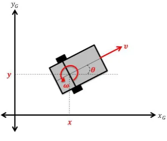
4.1 Differential Drive Kinematics
The KheperaIII robot is a differential mobile robot. The differential robot is the robot that depends on only two wheels to move. Both wheels are mounted on the same axis but are driven by different actuators. By varying the speeds of the two motors, the robot can perform different types of motion.
[image:4.595.346.488.187.271.2]The general requirements for any mobile robot to move are the linear and the angular velocities. However, the differential robots have only inputs for the velocity for each wheel in rpm. So, a controller function is used to change the required linear and angular velocities into the velocities of the left and right wheels.
Fig -3: Differential Robot Diagram
Dudek and Jenkin [22] introduced in their book the kinematics of the differential drive. The angular velocity of the robot at any instant is rotating around an Instantaneous Center of Curvature ICC. The radius of curvature R and the angular velocity of the robot
can be expressed by) (
) (
2 1
l r
l r
V V
V V R
and
l V Vr l)
(
(15)
where Vrand Vlare the left and right velocities, l is the
distance between the two wheels and R is the distance from the ICC to the midpoint of l.
The kinematics model of the differential drive can be represented as
l r
l r r r
l r r r
y x
) sin( 2
) cos( 2
) sin( 2
) cos( 2
(16)
Where T
y
x ]
[ is the position vector of the mobile robot, ris the wheel radius and[r l]Tis the right and left
wheels angular velocities.
4.2 V-REP
Virtual Robot Experimentation Platform (V-REP) is a robotic simulator that is used for the experimentation in this work. It is an open source software and it has direct link with MATLab. Its script can be written as MATLab script. It can be linked to MATLab as a remote API.
[image:4.595.75.245.473.616.2]The environment used in the simulations consists of KheperaIII mobile robots, Vertical Vision Sensor, Obstacles, 5mx5m Floor, and the goal will be marked in red point as in Figure 4.
Fig -4: The V-REP Environment used in the Simulations
5. RESULTS
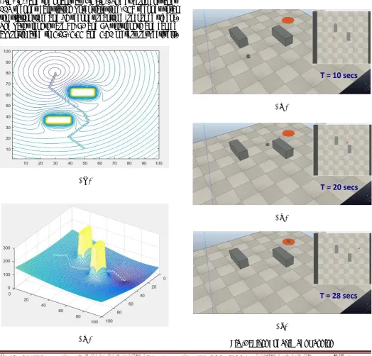
This model has two sides; MATLab and V-REP. The MATLab side will generate a 2D and 3D potential map for the environment while the V-REP will show real-time simulation for the trajectory tracking of the robots. In the camera screen, the goal is represented as an orange area, The floor size is 5m×5m, and the (0,0) is at the left and the (5,5) point is at the right. In the vision sensor screen, the robot is represented by a small red circle, the obstacles are gray
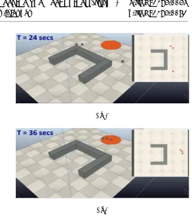
[image:4.595.308.561.494.610.2]rectangles, the point (0,0) is at the top left and the point (5,5) is at the bottom right of the vision sensor screen. The first experiment as in Fig. 5 has only one robot with two obstacles, to make initial test for the whole simulation. The robot is positioned at point (2.5,0.5), and the goal is at (1.5,4). The experiment takes 12 seconds calculating potentials time, 37 seconds total simulation time and 28 seconds real time (recorded video). The path length is 70 unit length and can be approximated to 4.22 meters. The samples are taken every 10 seconds as in Figure 5c, 5d, 5e and 5f. The last experiment as in Figure 6 has three robots with an obstacle. This obstacle has geometry to create a local minima point. The aim if this experiment is to test the multi-robot system with solving the local minima problem. The robots are positioned at points (1.5,0.5), (2.5,0.5) and (3.5,0.5), and the goal is at (2.5,4.5). The experiment takes 113 seconds calculating potentials time, 158 seconds total simulation time and 36 seconds real time (recorded video). The paths lengths are 86, 92 and 93 unit length and can be approximated to 5.19, 5.55 and 5.61 meters respectively.
The samples are taken every 12 seconds as in Figure 6c, 6d, 6e and 6f.
( c )
( d )
( e )
[image:5.595.37.562.280.782.2]( f )
Fig -5: First Experiment Results ( a )
( b )
( a )
( b )
( c )
( d )
( e )
[image:6.595.286.566.52.368.2]( f )
Fig -6: Second Experiment Results
6. CONCLUSION
Choosing specific path planning approach is a serious problem in any robotic application. Some applications need the path planning to be fast without focusing on how accurate it is. Other applications need the path is to be very accurate. APF is one of the classic approaches of the path planning, and it has more than one way to be implemented. APF concept is built on representing the robot environment with potential field, where the obstacles have high potential and the goal has low potential. This causes the robot to be attracted to the goal and in the same time repelled from the obstacles. In case of multi-robot system, every robot is an obstacle for the other robots, so the robots cannot collide with each other. The proposed approach combines both APF and Virtual Obstacles approaches. The validity of the proposed approach is tested and simulated using MATLab and V-REP as a real-time simulator. The experiments results show the effectiveness of this paper approach.
7. FUTURE WORK
using this approach on hardware, KheperaIII or similar mobile robots are the recommended robots to be used.
REFERENCES
[1] Ibrahim, A.A., Ghareeb, Z.S., Shehata, O.M., Morgan, E.S.I.:
A robotic surveillance platform based on an on-board computer vision approach. In: Proceedings of the 4th International Conference on Control, Mechatronics and Automation, pp.41-45. ACM (2016)
[2] Lima, P.U., Custodio, L.M.: Multi-robot systems. In:
Innovations in robot mobility and control, pp. 1-64. Springer (2005)
[3] Samuel, V.M., Shehata, O.M., Morgan, E.S.I.: Chaos
generation for multi-robot 3d-volume coverage maximization. In: Proceedings of the 4th International Conference on Control, Mechatronics and Automation, pp. 36-40. ACM (2016)
[4] Nabil, M., Kassem, M., Bahnasy, A., Shehata, O.M.,
Morgan, E.S.I.: Rescue missions bots using active slam and map feature extraction. In: Proceedings of the 4th International Conference on Control, Mechatronics and Automation, pp. 31-35. ACM (2016)
[5] Kassem, M., Shehata, O.M., Morgan, E.I.: Multi-modal
mobile sensor data fusion for autonomous robot mapping problem. In: MATEC Web of Conferences, vol. 42. EDP Sciences (2016)
[6] Jennings, J.S., Whelan, G., Evans, W.F.: Cooperative
search and rescue with a team of mobile robots. In: Advanced Robotics, 1997. ICAR'97. Proceedings., 8th International Conference on, pp. 193-200. IEEE (1997)
[7] El-Ansary, S., Shehata, O.M., Morgan, E.S.I.: Airport
management controller: A multi-robot task-allocation approach. In: Proceedings of the 4th International Conference on Control, Mechatronics and Automation, pp. 26-30. ACM (2016)
[8] Hussein, A., Adel, M., Bakr, M., Shehata, O.M., Khamis, A.:
Multi-robot task allocation for search and rescue missions. In: Journal of Physics: Conference Series, vol. 570, p. 052006. IOP Publishing (2014)
[9] Leena, N., Saju, K.: A survey on path planning techniques
for autonomous mobile robots. IOSR Journal of Mechanical and Civil Engineering (IOSR-JMCE) 8, 76-79 (2014)
[10] Rimon, E., Koditschek, D.E.: Exact robot navigation using
artificial potential functions. IEEE Transactions on robotics and automation 8(5), 501-518 (1992)
[11] Ge, S.S., Cui, Y.J.: New potential functions for mobile
robot path planning. IEEE Transactions on robotics and automation 16(5), 615-620 (2000)
[12] Ge, S.S., Cui, Y.J.: Dynamic motion planning for mobile
robots using potential field method. Autonomous robots 13(3), 207-222 (2002)
[13] Ge, S.S., Fua, C.H.: Queues and artificial potential
trenches for multirobot formations. IEEE Transactions on Robotics 21(4), 646-656 (2005)
[14] Hsieh, M.A., Kumar, V., Chaimowicz, L.: Decentralized
controllers for shape generation with robotic swarms. Robotica 26(5), 691-701 (2008)
[15] Nagy, I.: Behaviour study of a multi-agent mobile robot
system during potential field building. Acta Polytechnica Hungarica 6(4), 111-136 (2009)
[16] Saez-Pons, J., Alboul, L., Penders, J., Nomdedeu, L.:
Multi-robot team formation control in the guardians project. Industrial Robot: An International Journal 37(4), 372-383 (2010)
[17] Valbuena, L., Tanner, H.G.: Hybrid potential field based
control of differential drive mobile robots. Journal of intelligent & robotic systems pp. 1-16 (2012)
[18] Hargas, Y., Mokrane, A., Hentout, A., Hachour, O.,
Bouzouia, B.: Mobile manipulator path planning based on artificial potential field: Application on robuter/ulm. In: Electrical Engineering (ICEE), 2015 4th International Conference on, pp. 1-6. IEEE (2015)
[19] Rajvanshi, A., Islam, S., Majid, H., Atawi, I., Biglerbegian,
M., Mahmud, S.: An efficient potential-function based path-planning algorithm for mobile robots in dynamic environments with moving targets (2015)
[20] Ahmed, A.A., Abdalla, T.Y., Abed, A.A.: Path planning of
mobile robot by using modified optimized potential field method. International Journal of Computer Applications 113(4) (2015)
[21] Khatib, O.: Real-time obstacle avoidance for
manipulators and mobile robots. The international journal of robotics research 5(1), 90-98 (1986)
[22] Dudek, G., Jenkin, M.: Computational principles of
mobile robotics. Cambridge university press (2010)