© 2017, IRJET | Impact Factor value: 6.171 | ISO 9001:2008 Certified Journal | Page 1648
COST ANALYSIS AND COMPARISON OF A COMPOSITE DIAGRID FRAME
WITH BARE FRAME UNDER DYNAMIC LOADING
Mr. Avnish KumarRai
1, Dr. Rajeev Arya
2, Smt. Rashmi Sakalle
31 P.G. Student M. Tech Structure, Department of Civil Engineering, Truba Group of Institutions, Bhopal 2Director, Truba Group of Institutions, Bhopal
3Head Of Department, Department of Civil Engineering, Truba Group of Institutions, Bhopal
---***---Abstract -As now days a huge requirement of tall structure is needed due to increasing population in India, As India is a developing country which has moderate economy therefore cost of project plays a vital role in acceptance of technology and its application. In this paper, the author has compared the cost of construction of a high-rise building with and without diagrids.
Authors have analyses a G+11 storey building in different seismic zones with different types of soil using software Staad.pro V8i. Total eight cases were modelled and designed for comparison. At the end concluded that introduction of Steel diagrid members decreases the cost of same building. It was found that diagrid structure is also capable of reducing the effect of dynamic loading on building.
Key Words: Composite structure, cost comparison, high-rise building, STAAD.PRO
INTRODUCTION
The structural component of a project is probably the most easy to estimate. It is usually the most advanced during the design stages which paints the estimators a good ‘picture’ of the structural design even at the early stages. The main structural element that are defined early and are easily quantified but, more often, connections of structure are developed at later stages so estimators tend to assume the cost for the connections as percentage of the total concrete weight of the project cost. When estimating new-build structures this approach is widely accepted , since the structural connection costs are only a fraction of the overall cost and can easily be covered as an allowance, based on the estimator’s judgment. The main intention of this technical paper is to provide the reader a general understanding of cost analysis of a high-rise building using diagrids to enhance its lateral stability but also to check its cost of construction and understanding the potential impacts to a structural estimate. This will help an estimator weigh the cost impact of the structural connections so the allowances applied are rather more ‘educated’ than just a guess.
Kyoung (2011) studied the behavior of diagrid structure with floor twisting at different rates. He found that twisted tower perform better than straight tower under across wind loading. Optimal angle of twist is though not established.
Montuori et al., (2014) varied the diagrid density and angle of diagonal columns along the height for square plan. The models are compared in terms of structural weight and performances. The efficiency potentials of different models are discussed.
Giulia Milana et. al. (2015) analyzed a G+40 tall structure with Different diagrid structures were considered, namely, three geometric configurations with inclination of diagonal members of 42°, 60°and 75°, and geometry considered is 36 x 36 m in lateral dimensions, and 160 m tall structure with circular shape. In this work the consider seismic Zone IV and did pushover analysis and concluded that providing diagrid is not only making economical building but also much stable in terms of safety.
Harshita Tripathi et. al. (2016) Determined the effect of dynamic analysis on tall structures of different storey G+24, G+36 and G+ 48, with same dimensions in length and width directions as 36 m x 36 m. and work is done on csi Etab, an analyzing and designing tool with considering lateral forces both seismic as per 1893 part-1 and wind forces as per 875 part-3 and conluded that storey displacement and storey drift values are within the permissible limit and stiffness to the diagrid structural system which reflects the less top storey displacement.
Kiran Kamath et. al. (2015) performed a comparative study on a circular plan with different angels of diagrid are considered as 64.00°, 72.00°, 76.30° and 90.00°. the geometry of circular plan is G+36 storey tall structure with 3.6 m each floor height and 36 m diameter of lateral dimensions are provided, considering wind load as per 875 part3 and seismic zone III as per 1893 part-1. Compared the structure in terms of base shear, top storey displacement, concluded that As the angle of diagrid increases, axial rigidity of the diagonal columns decreases, time period is minimum for 72o whereas top storey displacement is minimum for angle of 64.0°.
OBJECTIVES:
1. To determine the behavior of composite diagrid structural system in a seismic zone III and V.
© 2017, IRJET | Impact Factor value: 6.171 | ISO 9001:2008 Certified Journal | Page 1649 3. To determine the variation in forces due to diagrid
structure under seismic forces.
4. Comparison of results in terms of Max story drift, max story displacement, base shear in seismic case, time period. 5. Comparison of cost between the bare frame and composite diagrid frame in zone III and zone V with soil condition soft and hard in each case.
METHODOLOGY:
STEP-1: First structure is modelled with and without diagrid element in STAAD.PRO with same plan area.
STEP-2: In step 2 application of seismic forces as per Indian standard 1893-part-1 is applied on the structures.
STEP-3: In this step both the structures compared to determine the use of implementation of diagrid.
STEP-4: By the use MS excel we plotted the result in the form of graph.
[image:2.595.316.554.83.302.2]GEOMETRY:-
Table -1: Geometry & load consideration
Type of structure Public building (G+11)
Plan dimension 20 m X 20 m
Total height of building 33 m
Height of each storey 3.0 m
Diagrid section Steel section
Angle of Diagrid 66o
Seismic zone III & V
Dead load IS 875-part-1
Live load IS 875-part-2
Seismic code IS 1893-2002
STRUCTURAL PLAN DETAILS:-
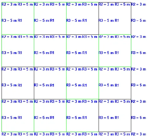
In fig no. 1 there is structural plan view of all the models having plan of 20m x 20m. In this plan R2 notation is for column and R3 notation is for beam and R1 notation is for slab. The structure is considered as a public building so live load on the building is 3 KN/m2. A member load of 11 KN/m is considered on all the beams for the wall loading. The end condition for diagrid is assumed as fixed. The support conditions are assumed as fixed. The angle of diagrid used here is 66o and the diagrid module which is used is a 2 storey module. The design of member is carried out on the basis of IS-456-2000. The design earthquake load is computed on the bases of IS 1893-2002 having zone factor 0.16, 0.35, soil type hard and soft, importance factor 1.5, Response Reduction 5.
Fig 1 STRUCTURAL PLAN
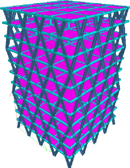
© 2017, IRJET | Impact Factor value: 6.171 | ISO 9001:2008 Certified Journal | Page 1650 Fig 3 Composite diagrid frame
[image:3.595.309.559.128.407.2]SECTION DETAILS:-
Table 2 Optimum section comparison for zone III soft soil
OPTIMUM SECTION COMPARISON FOR ZONE III HARD SOIL
SIMPLE FRAME FRAME WITH STEEL
DIAGRID SECTION
MATERIAL SIZE MATERIAL SIZE
EXTERIOR COLUMN
CONCRETE 700mm X 650mm
--- Replaced with diagrid
INTERIOR COLUMN
CONCRETE 700mm X 650mm
CONCRETE 650mm X 650mm
BEAM CONCRETE 400mm X 400mm
CONCRETE 300mm X 300mm DIAGRID --- NO STEEL ISLB 300
H
ANGLE OF DIAGRID
--- NO
--- degree 66
SLAB CONCRETE 150mm
thick
CONCRETE 150mm
thick
Table 3 Optimum section comparison for zone III hard soil:-
OPTIMUM SECTION COMPARISON FOR ZONE III HARD SOIL SIMPLE FRAME FRAME WITH STEEL
DIAGRID
SECTION MATERIAL SIZE MATERIAL SIZE
EXTERIOR COLUMN
CONCRETE 650mm X
650mm ---
Replaced with diagrid
INTERIOR COLUMN
CONCRETE 650mm X 650mm
CONCRETE 650mm X 600mm
BEAM CONCRETE 400mm X 400mm
CONCRETE 300mm X 300mm
DIAGRID NO STEEL
ISLB 300 H
ANGLE OF DIAGRID
NO --- degree 66
SLAB CONCRETE 150mm
thick
CONCRETE 150mm
thick
Table 4 Optimum section comparison for zone V soft soil:-
OPTIMUM SECTION COMPARISON FOR ZONE V SOFT SOIL
SIMPLE FRAME FRAME WITH STEEL
DIAGRID
SECTION MATERIAL SIZE MATERIAL SIZE
EXTERIOR COLUMN
CONCRETE 900mm X 900mm
--- Replaced with diagrid
INTERIOR COLUMN
CONCRETE 900mm X 900mm
CONCRETE
650mm X 650mm
BEAM CONCRETE 500mm X 500mm
CONCRETE
400mm X 400mm
DIAGRID --- NO STEEL ISLB
300H
ANGLE OF DIAGRID
--- NO --- 66 degree
SLAB CONCRETE 150mm
thick
CONCRETE 150mm
[image:3.595.37.559.436.793.2]© 2017, IRJET | Impact Factor value: 6.171 | ISO 9001:2008 Certified Journal | Page 1651 Table 5 Optimum section comparison for zone V hard
soil:-
OPTIMUM SECTION COMPARISON FOR ZONE V HARD SOIL
SIMPLE FRAME FRAME WITH STEEL DIAGRID
SECTION MATERIAL SIZE MATERIAL SIZE
EXTERIOR COLUMN
CONCRETE 800mm X 750mm
Replace d with diagrid
INTERIOR COLUMN
CONCRETE 800mm X 750mm
CONCRET
E 650mm X 600mm
BEAM CONCRETE 450mm X 450mm
CONCRET
E 350mm X 300mm
DIAGRID NO STEEL ISLB
300H
ANGLE OF DIAGRID
NO --- 66 degree
SLAB CONCRETE 150mm
thick
CONCRET
E 150mm
thick
RESULTS & ANALYSIS:
STOREY DISPLACEMENT:-
Analyses of the frames are done having consideration of different zones (III & V) and keeping the soil conditions hard and soft. The sections are provided in frames are the minimum requirement of the frames to maintain the stability of the structures. From the analyses, it is evident that the bare frame having huge storey displacement. To maintain the displacement in permissible limit have to provide column and beam of heavy sizes. In the bare frame, the heaviest columns are provided in zone v with soft soil condition. While exterior columns of the bare frame are replaced by the steel diagrid, it is seen that the storey displacements are reduced tremendously even the provided sections of interior column and beams are of much smaller size than compared with the bare frame. It is also found that by providing the heavy size of interior column and beams in our composite diagrid frame the displacement is reduced to a much higher extent. By the use of smaller interior columns and beam the diagrid frame become more economical than the bare frame and by the use of steel sections it is required less handling of material and during execution, much less formwork is required which includes another factor to make the frame economical. The analysis also shows that the value of axial force, shear force, and bending moments are also. The different displacement results are shown in below figures.
Chart 1: Storey displacement in seismic zone III with soft soil condition
Chart 2:- Storey displacement in seismic zone III with hard soil condition:-
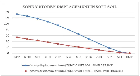
Chart 3:-Storey displacement in seismic zone V with soft soil condition:-
© 2017, IRJET | Impact Factor value: 6.171 | ISO 9001:2008 Certified Journal | Page 1652 The above graph shows the comparative storey
displacement in between bare frame and composite diagrid frame and it is evident from the graph that the story drift reduces in diagrid frame which means the diagrid frames are more stable with the bare frame for same environmental conditions.
BENDING MOMENT:
Chart 5:- Max bending moment in Zone III with soft soil condition:-
Chart 6 :- Max bending moment In Zone III with hard soil condition:-
Chart 7:- Max bending moment In Zone V with soft soil condition:-
Chart 8:- Max bending moment In Zone V with hard soil condition:-
The result shows that bending moment is decreasing in composite diagrid structure which means less reinforcement is required
AXIAL FORCE:-
Chart 9:-Axial force In Zone III with soft soil:-
© 2017, IRJET | Impact Factor value: 6.171 | ISO 9001:2008 Certified Journal | Page 1653 Chart 11:- Axial force In Zone V with soft soil:-
Chart 12:- Axial force In Zone V with hard soil:-
From the above four chart, it is evident that the axial force different in each case and it is less in zone V for composite diagrid frame as compared to the bare frame while in zone III axial force is more in composite diagrid frame as compared to the bare frame. The axial force increases by 6.30% in zone III with soft soil and increases with 5.30% in zone III hard soil.
SHEAR FORCE:-
Chart 13:-Shear force in Zone III with soft soil:-
Chart 14:-Shear force in Zone III with hard soil:-
Chart 15:-Shear force in Zone V with soft soil:-
Chart 16:-Shear force in Zone V with hard soil:-
It is evident from the above four chart of shear force for different zones with different soil conditions is also decreases in composite diagrid frame in all cases in comparison with the bare frame.
BENEFITS OF DIAGRID STRUCTURE
I. The stability of structure is increased due to implementation of triangular element.
© 2017, IRJET | Impact Factor value: 6.171 | ISO 9001:2008 Certified Journal | Page 1654 III. The gravity and lateral load transferring system
providing more efficiency.
COST ANALYSIS:-
On the basis of above result and analysis calculate and compare the cost of the bare frame and the frame with diagrids at the outer periphery and the results are shown in below charts. The analysis shows that in earthquake zone the bare frame required heavy size of beam and column to maintain their stability due to which the consumption of concrete and reinforcement are increasing in the bare frame structure while in the case of composite diagrid frame required less size of beam and column in comparison to bare frame which reduces its reinforcement and concrete in huge amount. Let study the comparison of cost of both frames by the help of two different cases:-
I. If we talk about the zone v case of soft soil the total weight of reinforcement and steel, as well as the volume of concrete, are decreased in huge amount as compared to the weight of reinforcement of bare frame and volume of concrete.
II. If we talk about the zone V case of hard soil and zone III either case of soft soil or hard soil, in the composite diagrid frame the total weight of steel and reinforcement are more than the weight of reinforcement in diagrid frame but in this case the concrete consumption in composite diagrid frame is still reduced in huge amount.
So in both the above conditions it is evident that the composite diagrid frame is more economical than the bare frame as in zone V due to the reduction of both steel and concrete while in zone III due to the reduction of concrete only.
The quantity of material used in bare frame and composite diagrid frame for different zones with the different soil conditions are shown in below charts:-
[image:7.595.311.559.102.252.2]CONCRETE:-
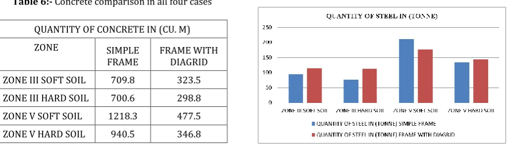
Table 6:- Concrete comparison in all four cases
QUANTITY OF CONCRETE IN (CU. M)
ZONE SIMPLE
FRAME FRAME WITH DIAGRID
ZONE III SOFT SOIL 709.8 323.5
ZONE III HARD SOIL 700.6 298.8
ZONE V SOFT SOIL 1218.3 477.5
ZONE V HARD SOIL 940.5 346.8
Chart 17:-Quantity of concrete in graphical form
As shown in above chart amount of concrete in a simple frame will be comparatively higher than diagrid frame as outer R.C.C. columns are replaced by steel sections in diagrid frame. So the concrete consumption in all the cases for the bare frame is much higher than the composite diagrid frame which makes the bare frame more costly than the composite diagrid frame.
[image:7.595.48.560.602.748.2]STEEL:-
Table 7:-Steel comparison in all four cases
QUANTITY OF STEEL IN (TONNE)
ZONE SIMPLE FRAME FRAME WITH DIAGRID
ZONE III SOFT SOIL 95.248 115.385
ZONE III HARD SOIL 76.534 113.234
ZONE V SOFT SOIL 210.674 176.462
ZONE V HARD SOIL 134.718 144.575
Note:- Here steel in the case of diagrid is the total quantity of steel sections and reinforcement while in simple frame the steel is refer for reinforcement only.
© 2017, IRJET | Impact Factor value: 6.171 | ISO 9001:2008 Certified Journal | Page 1655 As shown in figure above it is clearly determined that as
outer column are removed by diagrid system it manages bending moment properly that reinforcement requirement including steel for diagrid is comparatively less than bare frame in zone V with soft soil condition while in other zones there will be a slight increment of weight of steel, the maximum increment of steel is 32.4% in zone III hard soil but on the same place concrete is reduces with 57.35% in zone III hard soil thus the overall cost for the frame is reduces for each case which makes the composite diagrid frame structure more economical than the bare frame structure.
CONCLUSIONS
In this study, it is shown that by providing diagonal columns at the outer periphery of the structures, the composite diagrid structure is more effectively resist the lateral load in comparison with the bare frame structure.
By providing the concept of a diagonal column at the outer periphery of the structure the column at the interior part of the structure is used for resisting very small gravity load and a little amount of lateral load whereas in bare frame structure gravity load and lateral load are transferred by both interior as well as exterior column.
Due to this phenomenon of replacing vertical column at an outer periphery of the bare frame structure, there is a huge reduction of concrete in the diagrid structure while the steel may vary on bases of conditions but due to the reduction of concrete in huge percentage stills make the diagrid structure more economical than the bare frame structure.
The different points concluded from the above study:-
The composite diagrid frame providing in zone V with soft soil condition is 32.82% more economical than the bare frame structure as in this case both steel and concrete are reduced in composite diagrid frame as the provided adequate section for beam and column is much smaller.
Due to the change of soil condition from soft soil to a hard soil in zone V the steel in composite diagrid frame slightly increases with 6.82% while on the same place the concrete is reduced with 63.13% so overall it makes the diagrid frame 22.06% more economical in this case.
In zone III with soft soil condition the steel increases in composite diagrid frame with 17.45% while concrete reduces with 54.42% so this makes diagrid frame 11.58% more economical.
In zone III with hard soil condition the steel increases in diagrid frame 32.41% while still the concrete is reduced by 57.35% in comparison with the bare frame which makes diagrid 3.02% more economical.
As we talk about the huge concrete reduction in each case is solely because the replacing of an exterior column with steel diagrid as well as the interior column required for the carry the gravity load in diagrid frame is of much smaller in size of the bare frame.
REFERENCES
[1]. Clark W, Kingston J. 1930. The Skyscraper: A Study In The Economic Height Of Modern Office Buildings. American Institute of Steel Construction: New York.
[2]. Khan, F.R., & Sbarounis, J. (1964). Interaction O Shear Walls and Frames In Concrete Structures Under Lateral Loads. Structural Journal of the American Society of Civil Engineers, 90(St3), 285‐335.
[3]. Khan, F.R. (1969). Recent Structural Systems In Steel For High‐Rise Buildings. In Proceedings of The British Constructional Steelwork Association Conference on Steel In Architecture. London: British Constructional Steelwork Association.
[4]. A. G. Davenport, “The Response of Six Building Shapes to Turbulent Wind”, Seria A, Mathematical and Physical Sciences. Vol. 269, No. 1199, A Discussion on Architectural Aerodynamics, 1971, Pp. 385‐394.
[5]. Khan, F.R. (1973). Evolution of Structural Systems For High‐Rise Buildings In Steel And Concrete. In J. Kozak (Ed.), Tall Buildings In The Middle And East Europe: Proceedings of The 10th Regional Conference On Tall Buildings‐Planning, Design And Construction. Bratislava: Czechoslovak Scientific and Technical Association.
[6]. Popov, E.P. (1982). Seismic Framing Systems for Tall Buildings. Engineering Journal/American Institute of Steel Construction, 19(Third Quarter), 141‐149.
[7]. Council on Tall Buildings And Urban Habitat. 1995. Structural Systems for Tall Buildings. Mcgraw‐Hill: New York.
1’st Author
Photo
Completed B.E In 2013 From Girdhar Group Of Institution Bhopal Affiliated To R.G.P.V Bhopal , Persuing M.Tech From Truba Group Of Institutions, Affiliated To R.G.P.V Bhopal
[8]. Aisc. 1998. Manual of Steel Construction: Load And Resistance Factor Design. American Institute of Steel Construction: Chicago,
BIOGRAPHIES