A Steganography Technique for Hiding Image in
an Image using LSB Method for 24 Bit Color Image
Deepesh Rawat
MTech (DC 2nd Year) BTKIT,DWARAHAT UTTARAKHAND, INDIA
Vijaya Bhandari
Asst. Professor (ECE ), BTKIT,DWARAHAT, UTTARAKHAND, INDIA
ABSTRACT
In this paper, author have propose a steganographic technique by using improved LSB (least significant bit) replacement method for 24 bit color image capable of producing a secret-embedded image that is totally indistinguishable from the original image by the human eye. In addition this paper shows that how improved LSB method for 24 bit color image is better than LSB technique for 8 bit color image. Firstly LSB method for both 8 bit and 24 bit color image are described and then improved LSB method for 24 bit color image, compare their result by calculating PSNR (Peak Signal-to-Noise Ratio), MSE (Mean Squared Error) and finally by histogram analysis. LSB Algorithm embedded MSB of secret image into LSB of cover image. In the case of 24 bit color image two methods are described. In first method, last 2 LSB of each plane (red, green and blue) of cover image, is replaced by 2 MSB of secret image. In the second method, last LSB of each red plane is replaced by first MSB of secret image, last 2 LSB of each green plane by next 2 MSB of secret image and then last 3 LSB of blue plane is replaced by next 3 MSB of secret image. This means that total 6 bits of secret image can be hide in 24 bit color image. Experimental results show that the stego-image is visually indistinguishable from the original cover-image in the case of 24 bit.
Keywords:
Cover image, Data hiding, Histogram, LSB method, MSB, PSNR, Steganography; Stego-image1. INTRODUCTION
The idea of information hiding is nothing new in the history. As early as in ancient Greece there were attempts to hide a message in trusted media to deliver it across the enemy territory. In the modern world of digital communication, there are several techniques used for hiding information in any medium. One of such technique is steganography[1] in which digital media mainly digital images are used as a medium for hiding information and the information in the form text, digital image, video or audio file may be used as secret message. The word steganography derived from two Greek words: steganos means covered and graphos means writing and often refers to secret writing or data hiding[2]. The major goal of steganography is to increase communication security by inserting secret message into the digital image, modifying the redundancy or nonessential pixels of the image[3],and is recently become important in a number of application areas especially military and intelligence agencies which require unobtrusive communications. Digital images stored in computer systems are composed of finite number of elements in the form of array, each element has its particular location and value, mostly known as pixels. In case of 24 bit color image each pixel has three color components: Red, Green, and Blue (RGB). Each pixel is represented with three bytes to indicate the intensity of these three colors (RGB). Steganography is quite differ from cryptography in the sense
that where cryptography focuses on keeping the contents of a message secret, steganography focuses on keeping the existence of a message secret [4]. Cryptography is derived from Greek word kryptós, means hidden, and gráphein means to write and is the study of means of converting information from its normal, comprehensible format into an incomprehensible format. Its main aim is to present message in unreadable format without secret knowledge, known as the encryption. Steganography and cryptography are both ways to protect information from unwanted parties but neither technology alone is perfect and can be compromised. If the presence of hidden information is suspected or even revealed, the purpose of steganography is partly defeated [4]. Cryptography and Steganography achieve the same goal via different means. Encryption encodes the data into an unreadable format called cipher so that an unintended recipient cannot determine its intended meaning. On the other hand steganography attempts to prevent an unintended recipient from suspecting that the data is there [5]. Nowadays, using a combination of steganography and the other methods such as cryptography, information security has improved considerably. In addition to being used in the covert exchange of information, steganography is used in many other fields such as copyright, preventing e-document forging. For the past decade, many steganographic techniques for still images have been presented. A simple and well known method is directly hiding secret data into the least-significant bit (LSB) of each pixel in an image. Then based on the LSB technique, an algorithm for 24 bit color image is developed improves the stego-image quality of color image.
2. 8 BIT COLOR IMAGE
Bit 7 6 5 4 3 2 1 0
[image:2.595.62.272.82.217.2]Data R R R G G G B B
Table 1. 8 bits representing color
Fig 1. 8-bit color, with 3 bits of red, 3 bits of green, and 2 bits of blue
3. 24 BIT COLOR IMAGE
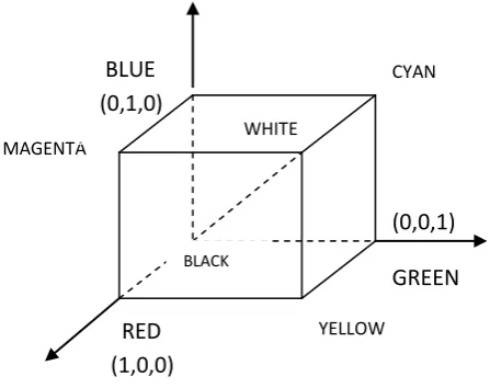
24 bit color image is best define by RGB color model in which each color appears in its primary spectral component of red, green and blue. This model is based on Cartesian coordinate system shown in Fig 2. In which RGB primary value are at three corner ,the secondary color cyan , magenta and yellow are at three other corner, black is ate the origin and white is at the corner farthest from the origin. Line joining the two corners has equal values for red, green and blue.
Fig 2. Schematic of the RGB color model
This produces various shades of grey. The locus of all these points is called the grey line. In RGB model, each pixel is composed of RGB values and each of these colors requires 8-bit for its representation. Hence each pixel is represented by 24 bits. So total number of color possible with 24-bit RGB image is (28)3 = 16,777,216
4. LEAST SIGNIFICANT BIT
LSB based technique is most simple and straightforward approach in which message bits are embed in least significant bits of cover image. In LSB steganography, the least significant bits of the cover media’s digital data are used to conceal the secret message [6]. LSB Steganography can be classified by two methods LSB replacement and LSB matching. The terminology LSB replacement/ LSB matching was firstly discussed by T. Sharp [7]. First is LSB replacement which is simplest of the LSB steganography techniques. LSB replacement steganography replace the last
bits of cover image with each bits of the message that needs to be hidden.
Second method is LSB matching [8] in which each pixel of the cover image is taken mainly in a pseudo-random order which is generated by a secret key, if the LSB of the cover pixel matches the bit of secret data no changes are done otherwise, one is added or subtracted from the cover pixel value, at random. If the length of secret message contains fewer bits than the number of pixels in the cover image, changes are spread uniformly throughout the image by pseudo-random permutation. Since there is change of each bits by so the degradation of cover image caused by this embedding process would be perceptually transparent. In LSB of 24 bit color image, the least significant bit of each pixel of a specific color channel or all color channels are replaced with a bit from the secret data. For RGB we analysis this LSB replacement technique [6] that replace least two significant bits of each channels Red, Green or Blue with message bits. Altering the LSBs will only cause minor changes in color, and thus is usually not noticeable to the human eye. Algorithm[9] for LSB Based embedding and extracting process is given as-: A LSB-based Embedding Algorithm
Input -: cover C
for i = 1 to Length(c), do Sj Cj
for i = 1 to Length(m), do
Compute index ji where to store the ith message bit of m
Sji LSB(Cji) = mi
End for
Output -: Stego image S
A LSB-based Extracting Algorithm Input -: Secret image s
for i = 1 to Length (m), do
Compute index ji where to store the ith message bit of m
mji LSB(Cji)
End for
In the extraction process, the embedded messages can be readily extracted without referring to the original cover-image from the given stego-image S. The set of pixels storing the secret message bits are selected from the stego-image, using the same sequence as in the embedding process. The n LSBs of the selected pixels are extracted and lined up to reconstruct the secret message bits
4.1. LSB Method For 8 Bit Color Image
Consider an 8-bit color image fig 4.1 where each pixel is stored as a byte representing a grayscale value. Suppose the first three pixels of the original image have the following values:
[11 00 1001 11011110 11101001] And that of secret image fig 4.2 is : [11100101 10110110 11110001]
Firstly removing the last 4 LSB of cover image by multiplying each pixel with [11110000]. In Matlab it is done by using “bitand” command, resulting original image pixels [11000000 11010000 11100000]. After shifting secret image pixels bits by 4 toward right and then adding with original cover image pixel by using “bitor” command, last 4 LSB of cover image get replaced by first 4 MSB of secret image and we get stego image fig 4.3 whose first three pixels are :
[11001110 11011011 11101111] BLACK
WHITE
CYAN
MAGENTA
YELLOW W
RED
(1,0,0)
BLUE
(0,1,0)
(0,0,1)
[image:2.595.53.277.371.548.2]Fig 4.1 Cover image
Fig 4.2 Secret image
Fig 4.3 Stego image
4.2.
LSB Method For 24 Bit Color Image
In the case of 24 bit color image each pixel is composed of RGB values and each of these colors requires 8-bit for its representation. [R (8 bits), G (8 bits) , B (8 bits)]. If we read color image fig 4.2.1 in Matlab and display its first pixel, we get-:>> a = imread(‘coverimage.jpg’) >> a (1,1,1) = 220
>> a (1,1,2) = 198 >> a (1,1,3) = 135
Here last term (1, 2 and 3) represent RGB component of pixels (1,1) So RGB first pixel can be represent as
[11011100 11000110 10000111]
For embedding secret image fig 4.2 whose first pixel is [11001001] firstly we have to replace last 2 LSB of each of RGB component and then embedding first 2 MSB of first pixel of secret image to R component, then next 2 MSB of first pixel of secret image to G component and lastly another next 2 MSB of first pixel of secret image to B component. In this way we get stego image whose first pixel is:
[11011111 11000100 100000110].
[image:3.595.363.491.70.437.2]In this method 6 bits of secret image get hide by replacing only 2 bits of RGB component so stego-image is visually indistinguishable from the original cover-image in the case of 24 bit
Fig 4.2.1. Cover image
Fig 4.2.2. Secret image
Fig 4.2.3. Stego image
4.3. Improved LSB Method For 24 Bit
Color Image
In this method cover image is 24 bit color image. This cover image is first split into its 3 plane (red, green, blue). The main aim of this method is to hide most of the secret image bits in blue plane rather than red and green. Blue plane is selected because a research was conducted by Hecht, according to which 65% of all cones of human eyes are sensitive to red, 33% are sensitive to green, and only near about 2 % are sensitive to blue, as a result visual perception of intensely blue objects is less distinct that the perception of objects of red and green.
Steps to be carried out in this technique and implement in MATLAB are-:
1) Select the cover image, multiply the red plane by 254 to make last bit 0 : by “bitand(c(x,y,1), uint8(254))” command. Obtain first MSB i.e. 8th
bit of secret image and then embedded it in last LSB of red plane
2) Now take green plane of cover image and convert its last 2 LSBs to 0 by “bitand” command, multiplying each pixel with 252 : “bitand(c(x,y,2), uint8(252))”. Obtain next to MSB i.e 7th
[image:3.595.366.493.72.182.2]3) Lastly take blue plane of cover image and convert its last 3 LSBs to 0 by “bitand” command multiply each pixel by 248: “bitand(c(x,y,3), 248)”. Obtain next 3 MSB i.e. 5th, 4th and 3rd bit of secret image and embedded it into blue plane
So if 24 bit color image first pixel is represent as [11011100 11000110 10000111]
Then for embedding secret image whose first pixel is [11001001], we follow above step and get stego image whose first pixel is: [11011101 11000110 100000010].
Stego image obtain by this method is shown in fig 4.3.1. using same cover image and secret image as used in above case
Fig 4.3.1. Stego image obtain using improved LSB method
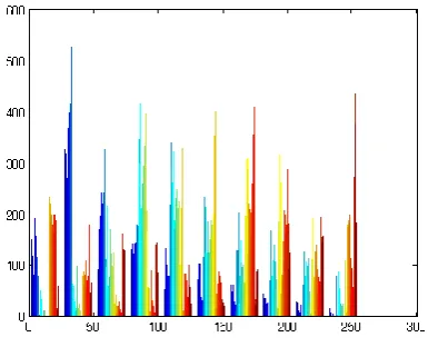
5. Histogram Analysis
One of the best way of finding out a good steganography technique is the analyzing the histogram of all stego image and then compare them with original one. Histogram represents the number of pixels that have colors in each of a fixed list of color ranges, that span the image's color space, the set of all possible colors.
[image:4.595.334.524.82.244.2]Fig5.1. Histogram of cover image
[image:4.595.96.240.204.310.2]Fig 5.2. Histogram of stego image of 8 bit color image
Fig 5.3. Histogram of stego image of 24 bit color image
Fig 5.4. Histogram of stego image of 24 bit color image (Improved LSB method)
[image:4.595.72.265.470.626.2] [image:4.595.333.534.483.637.2]6. SIMULATION RESULT
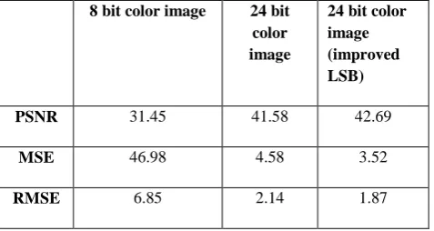
In steganography technique PSNR (Peak Signal-to-Noise Ratio), MSE(Mean Squared Error) and RMSE(Root Mean Square Error) are standard measurement used in order to test the quality of the stego images. MSE measures the average of the squares of the errors. The error is the amount by which the pixels value implied by the stego image differs from the cover image. PSNR, define ratio between the maximum possible power of a signal and the power of corrupting noise that affects the fidelity of its representation. The signal in this case is the cover image, and the noise is the error introduced by bits of secret image. Higher the value of PSNR, more the quality of the stego image. Let us consider, the cover image C of size M × M and the stego image is S of size N × N, then each cover image C and stego image S will have pixel value (x, y) from 0 to M-1 and 0 to N-1 respectively. The PSNR and MSE is then calculated as follows [10]:
PSNR = 10 log 10
(db) Where
MSE =
2
Here, αi,j is the pixel of the cover image where the coordinate
is (i, j), and βi,j is the pixel of the stego-image where the
coordinate is (i, j). M and N represent the size of the image. A larger PSNR value indicates that the difference between cover image and the stego-image is more invisible to the human eye.
8 bit color image 24 bit
color image
24 bit color image (improved LSB)
PSNR 31.45 41.58 42.69
MSE 46.98 4.58 3.52
[image:5.595.49.288.383.510.2]RMSE 6.85 2.14 1.87
Table 2 -: Comparison of PSNR, MSE and RMSE
6. CONCLUSION
In this paper we have described 2 way of applying LSB method to 24 bit color image and then compare its result with 8 bit color image. For comparison we have used PSNR (peak signal to noise ratio), MSE(Mean Squared Error) and histogram analysis which shows that PSNR for 24 bit color image is higher than that of 8 bit color image and MSE is quite low as shown in table 2, that is stego image quality becomes better. Also histogram comparison shows that in the case of 24 bit color image, stego-image is visually
indistinguishable from the original cover-image. In 8 bit color image 4 MSBs out of total 8 bits of secret image get embedded in cover image so while extracting secret image back we get an image that contain only 4 bits i.e it got slightly distorted. But in another case, first 6 MSB of secret image get embedded in RGB component, so while extracting secret image back we get an image containing 6 MSB, since LSB doesn’t contain any information there is no loss of information and secret image recovering back become undistorted
7. REFERENCES
[1]. M. M Amin, M. Salleh, S. Ibrahim, M.R.K atmin, and M.Z.I. Shamsuddin “Information Hiding using Steganography” 4* National Conference on Telecommunication Technology Proceedings, Shah Alam, Malaysia. 2003 IEEE.
[2] Moerland, T., “Steganography and Steganalysis”, Leiden Institute of Advanced Computing Science, www.liacs.nl/home/ tmoerl/privtech.pdf
[3] Feng, J.B., Lin, I.C., Tsai, C.S., Chu, Y.P., 2006. Reversible watermarking: current status and key issues. International Journal of Network Security 2 (May), 161– 170.
[4] Wang, H & Wang, S, “Cyber warfare: Steganography vs. Steganalysis”, Communications of the ACM, 47:10, October 2004
[5] Westfeld, A., and G. Wolf, Steganography in a Video conferencing system, in proceedings of the second international workshop on information hiding, vol. 1525 of lecture notes in computer science,Springer, 1998. pp. 32-47.
[6] Chan, C.K., Cheng, L.M., 2004. “Hiding data in images by simple LSB substitution”. Pattern Recognition 37 (March), 469–474.
[7]. T. Sharp, “An implementation of key-based digital signal steganography,” in Proc. Information Hiding Workshop, vol. 2137, Springer LNCS, 2001, pp. 13–26.
[8] R. Chandramouli and Nasir Memon, "Analysis of LSB Based Image Steganography Techniques", IEEE 2001. [9] Neil F. Johnson, S.C. Katzenbeisser,”A survey of
steganography technique”
[10] Chung-Ming Wang a, Nan-I Wu a, “A high quality steganographic method with pixel-value differencing and modulus function”, accepted 24 January 2007
[11] Mohammad Tanvir Parvez and Adnan Gutub, “RGB Intensity Based Variable-Bits Image Steganography”, APSCC 2008 – Proceedings of 3rd IEEE Asia-Pacific Services Computing Conference, Yilan, Taiwan,