, ~
tDLEX
TM
STD-PI02
@]
'
FEATURES
o STD-Z80 Bus compatible
o Four 8-bit parallel 110 ports
o Two fully independent channels, each
containing
- Two 8-bit input, output or bidirec-tional I/O ports with handshake
- One 4-bit special purpose port (four
handshake modes)
- Three independent and fully
fea-tured 16-bit counter/timers
- Pattern recognition logic for each
8-bit port (for interrupt control) - 110 port A configurable to
Centronics printer standard
o Selectable I/O port polarity
o Ports linkable for 16-bit I/O
o 4 MHz operation
o Single 5 volt supply o 1 year warranty
D
E
SCR
I
PT
I
ON
The STD-PIOZ is a general purpose
paral-lel I/O card for the STD Bus. The card contains two high performance ZILOG
Z8536 CIO devices, each one combining
the features of both a PIO and a CTC. All
necessary support logic and control cir-cuitry to provide two complete and
sepa-rately configurable parallel I/O channels (ONE and TWO) is included on the
board. The 8-bit 110 ports are fully
buff-ered and can be individually configured for input, output, or bidirectional
opera-tion. The user can configure any 8-bit
port(s) for inverting operation through
programming. All Z-80 interrupt modes
are supported by the STD-PIOZ.
The six 16-bit counter/timers (three in
each 8536 CIO) are identical and
inde-pendent. Three different output signal
duty cycles are available from each
coun-ter/timer, and each is individually pro-grammable for either retriggerable or
non-retriggerable operation.
Each 8536 CIO device contains a special 4-bit control port. This port provides
handshaking control and signals for the
two 8-bit ports. Four modes of
handshak-ing are supported: interlocked, strobed,
pulsed, and 3-wire (port A only). The lines are buffered through Exclusive OR
gates allowing the user individual control
of the polarity for each signal.
Programmable configuration of the
STD-PIOZ by the system CPU is normally done at card initialization at which time all control and data registers are loaded. However, control register contents may be
examined and/or changed by the system CPU at any time. Individual enable bits
are provided for each major function block so that there will be no erroneous
operation before writing is complete.
COLE X AMERICA. INC PO Box 801462. Dallas. Texas 75380 United States 214/458·2779
CDLEX UK. LTD Index House. Ascot Berks SL57EU. England (09901·23377
51[)
BU<;
Pol! L
Channell
C10
Channel 2
CIO
SPECIFICATIONS
ELECTRICAL
o System Bus: STD-Z80
Inputs: one 74LS load maximum Outputs:Ioll = - 3mA
min
«I
2.4volts
101. = 24mA
min
«I
0.5volts
o System Clock: 4 MHz
o Data Bus: 8-bit, bidirectional
o Address Bus: 16-bit
o I/O Address: Any 8 Sequential Ports
o I/O Capacity: 4 general purpose 8-bit ports
1011 = - 3 mA min
((I 2.4 volts
101. = 24 mA min
(u 0.5 volts
o Interrupts: All three Z80 modes
o System Interrupt Units: 2 SIUs
o Operating Temperature: 0° C to 60° C.
o Power Requirements
«I
25° C:MECHANICI\L
o Card Dimensions:
Form Factor H W L Units
STD-Bus
I
0.60I
4.5 6.5 incheso PC Board Thickness: 0.062 inch
o Connectors:
STD-Z80 Bus: 56 pin, 0.125 inch
centers
Parallel: 26 pin, dual row. 0.100 inch
grid
16
16
2
16
lb
D
ponAPort B
O
""nrPort 0
ORDERING INFORMATION
Part Number Description
STD-PI02 4 port parallel I/O card
with handshake and
timers
STM-PI02 STD-PI02 Technical Manual
_ _ • T • ' ' ' ' - - ; _ ' 0 .~," - l ' , - , : , - . " ' , . . . . ~ . . . 'f;~-;010 .. ,~ J--i.J...,. .... ~-'~.-...~ .. '"'!IT"'-- "
Colex reserves the right to make changes to the CirCUitry or specifications without notice - .
Colex and the Colex logo are trademarks of Colex America. Inc. .'
(e1 Colex America. 1983 Printed In U S.A All rights Reserved Rev 1 1
FEATURES
o
STD-Z80 Bus Compatibleo
Four 8-bit Parallel 110 Portso
Two Fully Independent Channels, Each Containing:• Two 8-bit lnpu~ Outpu~ or Bi-directional 110 Ports with Handshake
•• One 4-bit Special Putpose Port (Four Handshake Modes)
• Three Indepen.dent and Fully Featured 16-bit CountetlTimers
• Pattern Recognition Logic for Each 8-Bit Port (for Interrupt Control)' • . 110 Port A ConAgurable to Centronics
Printer 'Standard
o
Selectable 110 Port Polarityo
Ports linkable for 16-bit 110o
4 MHz Operationo
Single +5 Volt Supplyo
1 Year WarrantyDESCRIPTION
The STD-PIOZ is a general purpose parallel
110
card for the STD Bus. The card contains two high performance ZILOG Z8536 CIO devices, each one combining the features of both a PIO and aere.
All necessary support logic and control circuitry to provide two complete and separately configurable parallel110
channels (ONE and TWO) is included on the board. The 8-bit 110 ports are fully buffered and can be individually configured for input, output, or bi-directional operation. The user can configure any 8-bit port(s) for inverting operationthrough programming.
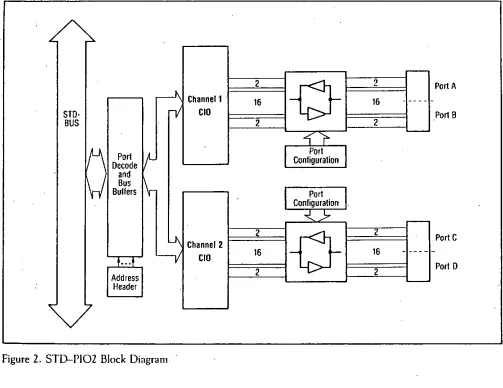
Each channel contains two independent 8-bit [10 ports (A and B), a 4-bit special purpose port (C), and three independent counterltimer channels. The 8536 C[O device is extremely powerful and versatile, and the STD-PI02 allows its features to be fully exploited through software and jumper selected options.
All Z80 interrupt modes are supported by the,
STO-PI02
'~-'.
PI02
•
. STD-PI02'
STD-PI02 and each 8-bit port contains pattern recognition logic and special registers to facilitate its use for interrupt control and prioritization. The' STD-PI02 is capable of interrupt arbitration . among internal and on-board sources and signals • are available for daisy-chained prioritizing of additional cards in the STD-Z80 Bus as well.
The six 16-bit counterltimers (three in each 8536 CIa) are all identical and independent. Three different output signal duty cycles are available from each counterltimer, and each is individually programmable for either retriggerable or non-retriggerable operation. Port B of each CIO device can
be
software configured to provide' access to two of the on-chip counterltimers and the third counterltimer is accessed through the 4-bit special purpose port.Each 8536 cIa device contains a special 4-bit control port. This port provides handshaking control and signals for the two 8-bit ports. Four modes of handshaking are supported: interlocked, strobed,
pulsed, and 3-wire (port A only). The lines are buffered through Exclusive OR gates allowing the user individual
! ,control ohhe polarity for each signal.
Programmable configuration of the STD-PI02 by the system CPU is normally done at card
initialization at which time all control and data' registers are loaded; however, contr~1 register • contents may be examined andlor changed by the
system CPU at any time. Individual enable bits are provided for each major function block so that there will be no erroneous operation before writing is complete.
Items to be loaded include interrupt vectors, prioritization insrructions, countet/timer
parameters, and so on. Other options are selected by strapping pins on control headers. Care has been taken to ensure that jumper connections occur directly across the header where ever practicable allowing options to
,---l\ Channel1
STD·
iii
CIOBUS
1fJ\
PortItI-Decode and
1\-/
BusI\-Bullers
11I
Channel 2,_::r
'-v
CIOAddress Header
~
Figure 2. STD-PI02 Block Diagram'
STD-PI02
be
selected by simple insertion of BergN type jumpers. In these and other cases, wire-wrapping is satisfactory as welLFor detailed operation and programming , , : procedures and other information on the 8536
CIO device, specific data on the support devices,
2
16
2
2
16
2
" programming and operation of interrupt controllers, or detailed description or analysis beyond what is presented here, consult the various 7400 TTL data
I books, and Zilog Z801B> CPU and CIO technical
manuals and data sheets.
Centronics is a trademark of Centronics Corporation.
, 'NiBerg ~ a -trademark of the Berg Corporation.
'@Z80 is a registered trademark of the Zilog Corporation.
r
-V
216
._----2
Port A
Port B
~'r
'-Pori Configuralion
Pori Configuralion
~j,.
r
--0-
16 2-
" ---2
Pori C
Port D
'
-Page
.z
•
[image:4.601.45.548.348.736.2]JFB
,
,
..
26 14"
0 0 < ; 1 0 0 0 0 0 0 0 0 ( 1 0 0 0 0 0 0 0 0 0 0 0 0 0 0
0 0 0 0 0 0 0 0 0 0 0 0 0 0 0 0 0 0 0 0 0 0 0 0 0 0
JD
"
"
~
JC
J4
23 ro-o 24
• • • •
JA
"
23 0 0 24
21 0 0 n 19 0 0 211
" 0 0 Ie
I~ 0 0 16 tJ 0 0 14
110012
g o o 10
I 0 0 B
5 0 0 6
J 0 0 4 I 0 0 ,
14 26 0 0 , . 16
r"-:--:-::-::-:-:-::-::-::-::-:-'::i • • I r':':==-:-:-:-:-::-::':J
1 ° 0 0 0 0 0 0 0 0 0 0 0 0 0 . , 0 0 0 0 0 0 0 0 0 0 0 0 0 1
1 0 0 0 0 0 0 0 0 0 0 0 0 0 0 0 oooooooooooo~
JE 13 ~ ~ I JB 13
J3
J2
I' 0 0 12
9 0 0 III
1 0 0 a
5 0 0 6 3 0 0 4
, 0 0 2
• • • •
'~2
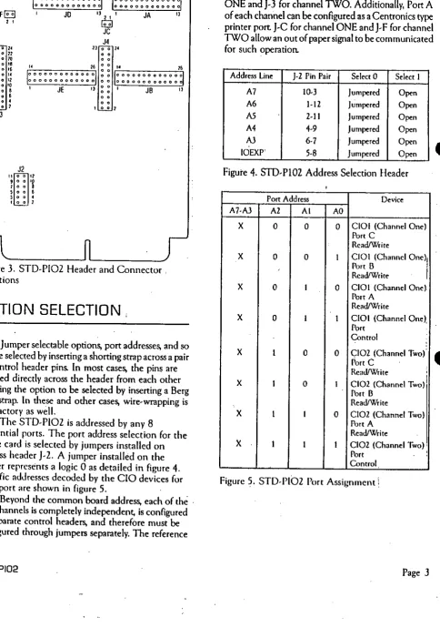
Figure 3. STD-PI02 Header and Connector . Locations
OPTION SELECTION
Jumper selectable options, port addresses, and so on are selected by inserting a shorting strnp across a pair of control header pins. In most cases, the pins are siruated directly across the header from each other allowing the option to be selected by inserting a Berg type strnp. In these and other cases, wire-wrapping is satisfactory as well.
The STD-PIOZ is addressed by any 8
sequential ports. The port address selection for the entire card is selected by jumpers installed on address header J-Z. A jumper installed on the header represents a logic 0 as detailed in figure 4. Specific addresses decoded by the
cia
devices for each port are shown in figure 5 .. Beyond the common
board
address, each of the . two channels is completely independent, is configured by separate control headers, and therefore mustbe
configured through jumpers separately. The reference
STO-PI02
designators of the control headers are J-4 for channel ONE and J-3 for channel TWO. Additionally, Port A of each channel can be configured as a Centronics type
printer port J-C for channel ONE and J-F for channel TWO allow an out of paper signal to be communicated for such operation.
Address Line }-2 Pin Pair Select 0 Select I
A7 IO-J }umpered Open
A6 1-12 }umpered Open
A5 2-11 Jumpered Open
A4 4-9 }umpered Open
AJ 6-7 }umpered Open
IOEXP' 5-8 }umpered Open
Figure 4. STD-PI02 Address Selection Header
Port Address Device
A7-AJ A2 Al AO
X 0 0 0 CIOI (Channel One)
Port C
ReadIWrite
X 0 0 I ClOI (Channel One)1
Port B
I
RcadfWrite
X 0 I 0 CIOI (Channel One)
Port A
ReadfWrite
X 0 I 1
cia
I (Channel One),Port
Control
X I 0 0 CI02 (Channel Two)
Port C
RcadIWrire ,
I
X I 0 1 CI02 (Channel Two) I
Port B
ReadIWrite
X I 1 0 CI02 (Channel Two)
Port A
RcadfWrite
X I I I CI02 (Channel Two)'
Port
:
Control
Figure 5. STD-PIOZ Port Assignment:
Page
J
•
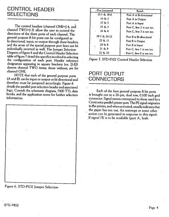
[image:5.601.81.566.154.844.2]CONTROL HEADER
SELECTIONS
c
The control headers (channel ONE=J-4, and channel1WO=J-3) allow the user to control the directions of the three ports of each channel The general purpose B-bit ports can
be
configured asbi-directiona~ inpu~ or output through these headers,
and the sense of the special purpose port lines can
be
individually inverted as well The Jumper Selection Diagram of figure 6 and the Control Header Selection table of figure 7 detail the specifics involved in selecting the configuration of each port Header reference designators appearing in square brackets (ex. U-ED denote channel 1WO items; those withou~ are for channel ONENOTE that each of the general purpose ports (A and B) can be input or ourput or bi-directional and therefore must be jumpered accordingly. Figure 6 details the parallel port selection header and associated logic. Consult the schematic diagram, 7400
TrL
data books, and the application notes for further selection information.Figure 6. STD-PI02 Jumper Selection
STD-PI02
; Pins Jumpered Result
1)·1 & 18-6 Port A is Bi-directional
14 & 2 Port A is Output
17 & 5 Port A is Input
15 &3 Pon C, line 2 is not iny.
16 &4 Port C. line 3 is not inv.
19·7 & 24-12 Port B is Bi~directional
23 & 11 Port B is Output
20 &8 Port B is Input
21 &9 Port C. line 1 is not inv.
22 & 10 I Pon C. line 0 is not in".
,Figure 7. STD-PlO2 Control Header Seleciion
PORT OUTPUT
, CONNECTORS
Each of the four general purpose B-bit ports is brought out to a 26-pin, dual row, 0.100 inch grid connector. Signal names correspond to those used by a Centronics parallel printer port The PE signal originates in (he printer, and whenactivate~ usually indicates that , the paper has run out An interrupt or some other . action can be generated in response to this signal.
.If signal PE is to be available (port A, both
Page 4
•
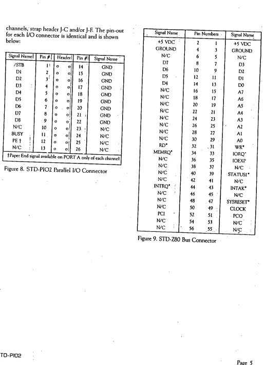
[image:6.602.11.561.99.804.2]channels; strap header J-C and/or J-E The pin-out for each 110 connector is identical and is shown below:
Signal Nam~ Pin
#1
Header! Pin #1Signal Name:
ISTll 11 0
:/
14 GNDDI 2
,
0 15 GNDoj
D2 3' 0 16 GND
D3 4 0
01 17 GND
D4 5 0
01 18 GND
D5 6 0
:1
19 GNDD6 7 0 20 GND
D7 8 0 0 1
,
21,
GNDD8 9 0 0 22 GND
NlC 10 0 o! 23 , NlC
BUSY 11 0 o! 24 NlC
PE t ! , 12 0 01 25 NlC .N/C 13 0 oj 26
NlC tPape, End signala",ilable on PORT A only of each channel:
Figure 8. STD-PIOZ Parallel 110 Connector
STO-PI02
Signal Name. Pin Numbers . Signal Nam~
+5 VDC 2 I +5 VDC
GROUND 4 3 GROUND
NlC 6 5 NlC
D7 8 7 OJ
D6 10 9 D2
D5 12 11 DI
D4 14 13 DO
NlC 16 15 . A7 NlC 18 17 A6 NlC 20 19 A5
Wc
Z2 21 A4•
NlC 24 23 A3Nle 26 25 A2 NlC 28 27 AI NlC 30 29 AO
RD' 32 .31 WR'
MEMRQ' 34 33 IORQ" NlC 36 35 IOEXP NlC 38 37 NlC NlC 40 39 STATUS1' NlC 42 41 N/C INTRQ'
,
44 43 INTAI<'NlC 46 45 NlC NlC 48 .47 SYSRESET' NlC 50 49 CLOCI< PCI
,
52 51 PCO NlC 54 53 NlC NlC 56 55 .. NlC [image:7.603.44.558.102.812.2]•
Figure
9. STD-ZSO
Bus Connector..
,
,
SPECIFICATIONS
ELECTRICAL
o
System Clock: 4 MHzo
Data Bus: 8-bit; bi-directionalo
Address Bus: 16-bito
System Bus: STD-Z80. . Signal Loading: Inputs: One 74LS load maximum Outpu~ IOH- 3mA min @ 2.4
volts
10l
=24mA min @ 0.5 voltso
110
Address: Any 8 sequential portso
110 Capacity: 4 general purpose 8-bit ports Outputs: fOH=-3mA·@ 2.4 voltsIOL =24mA min @ 0.5 volts
2 special purpose 4-bit ports
o
Interrupts: All three Z80 modeso
System Interrupt Units: 2 SIUso
ap;,rating TemPerature:O°C
to 60°Co
·Power Requirement: @25°C
Parameter Condition Min Typ. M .. Units
Vcc ! - 4.75 5.00 5.25 volrs
Icc 5vdc
-
685 1186 rnA .MECHANICAL
o
Card Dimensions:Form F.'actor H W L Units
SID·Bus 0.60 4.5 6.5 inches
o
PC Board Thickness: 0.062 incheso
Connectors:STD-Z80 Bus: 56-pin, 0.125 inch centers
Seria~ 26-pin, dual row, 0.100 inch grid
STO-PI02
•
•
"
g
t
•
i
i
N
~
..
: N
,
.,,"
"
•
~ (
gEl
E •
•
~.
S
-"
-•
i ···
_ .. 0( . . .•
,
u
•
~~
~ ~
:
~
,,;
..,
•
~
•
~
~
'J
~
~
-~
~A
,
•
,
11
:
•
.
~
•
~
.
;;
.
~
,
;
rt----f1J
,---o
..
•
..
..
•
J
•
.
"'It f Itt'
o •
o •
,
~---JJ
o u
•
..
...
...:::=-
r;::=::-....:=--
rr=-I
d
1.1
;.
Ji
imm
1iijl
~
l
<>
r'
"'''0
I~
"
~~-r
..
'>0~
-
.
:: I ~
•
! '!!! ~:
I '
Ie
•
i
i
I!
Id
Ig
I:
!
I~
i i ~ I