Effect in Positioning Gold Nanoparticle inside Plasmonic
Solar Cell on Absorption, Reflection and Transmission
Norasikin M Nasar, Rosmila Abdul-Kahar
*, Nor Shamsidah Amir Hamzah, Fahmiruddin Esa,
Mirza Basyir Rodhuan
Department of Physics and Chemistry, Universiti Tun Hussein Onn Malaysia, Malaysia
Received August 2, 2019; Revised October 5, 2019; Accepted December 12, 2019
Copyright©2019 by authors, all rights reserved. Authors agree that this article remains permanently open access under the terms of the Creative Commons Attribution License 4.0 International License
Abstract
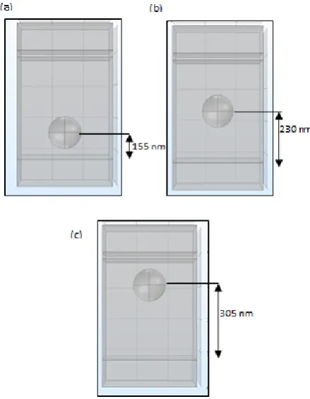
Gold nanoparticle has been explored in different ways to enhance the absorption of light and improve the efficiency of plasmonic solar cell. In this study, various positions of a gold nanoparticle which are at 115 nm, 230 nm and 305 nm measured vertically from the bottom of the solar cell to the centre of gold nanoparticle embedded into silicon layer of plasmonic solar cell is demonstrated using numerical simulation. The aim is to investigate the absorption, reflection and transmission percentage with different wavelength in different position of gold nanoparticle in plasmonic solar cell. The numerical results showed that the highest absorption and lowest reflection and transmission occurred at position 305 nm in the range 100 nm to 1000 nm compared to the simulation without nanoparticle and other position. The overall simulation results proved that at position 305 nm of gold nanoparticle which is near to the top layer is more efficient because this position has high electric field intensity in visible range.Keywords
Gold Nanoparticle, Absorption, Plasmonic Solar Cell, Nanoparticle Positioning, Numerical Simulation1. Introduction
Thin-film is a second-generation of silicon solar cells that may have the potential to provide viable routes towards minimized in costing problem. Thin film solar cell using plasmonic nanostructures has received attention from researchers with increase understanding about optical properties and development of new nanofabrication tools in plasmonic fields [1]. Plasmonic metallic’s nanoparticle like gold and silver has been explored as promising method in light trapping to enhance the optical absorption in plasmonic solar application [2-4]. Active semiconductor
like silicon perfectly trapped the sunlight. When using metal nanoparticle that embedded inside silicon substrate, more photons are available at surface plasmonic and it will cause electrons to become excited to create the current in the thin films solar cell [5]. This promising result has been demonstrated and validated by theory and experiments using different configurations in plasmonic solar cell like arranging the nanoparticle in square array on the top of silicon layer [6], embedded nanoparticle inside semiconductor [5][7], precise positioning on surface using scanning probe lithography [8] and position control of Ag nanoparticles [9]. The importance of the correct position of nanoparticles embedded into a material will give impact to absorption, reflection and transmission of light enhancement under study.
In this paper, various position of gold nanoparticle of plasmonic solar cells was explored to study the optical properties. The solar cell consists of various layers to generate electricity which is antireflection coating, active layer that embedded with nanoparticle and back reflector. Plasmonic solar cell using different position of gold nanoparticles was modelled using COMSOL Multiphysics.
2. Simulation Model
photocurrent for gold nanoparticle with sphere nanostructure was at radius 50 nm compared to other radius.
Figure 1. Schematic of plasmonic solar cell without nanoparticle
Figure 2. Schematic of gold nanoparticle at position (a) 155 nm (b) 230 nm and (c) 305 nm inside plasmonic solar cell
Finite Element Method (FEM) was used in this work to analyze the optical properties on gold nanoparticle inside plasmonic solar cell. The absorption was calculated in the wavelength ranging from100 nm -to 1000 nm to find the suitable range for solar cell using Beer-Lambert Laws that expressed as
0 10
log
I I
(1) where A is absorption, I is incident light intensities and I0 is transmitted light intensities after passing through the plasmonic solar cell [11-12]. The Beer-Lambert Laws gives the relationship between the light extinction and the distance of nanoparticle, d [13]. It shows an absorption effect that starts as
d ext
e
I
0I(d)
(2) where I0 is the input light intensity, I(d) is the unscattered light intensity measured after the distance, d and μext is the extinction coefficient. The extinction coefficient was calculated from the sum of the absorption μa and scattering μs coefficients.s
ext
a
(3)While, the equation of Fresnel equation was used to calculate reflection and transmission [14, 15] as
d transmitte 2
incident 1
d transmitte 2
incident 1
cos n cos
n
cos n -cos
n R
(4)
d transmitte 2
incident 1
incident 1
cos n cos
n
cos 2n T
(5)
where R is reflection, T is transmission, and n is refractive index. The refractive index, n for the material that is used in this study was taken from Rakic et.al (1998) which is 1.80 for ITO, 3.48 for Si, 0.48 for Al and 1.50 for Au [16].
3. Absorption for Gold Nanoparticle of
Plasmonic Solar Cell
In this section, the simulation results were shown in terms of absorption versus of wavelength for without nanoparticle and with nanoparticle at different positions which are 115 nm, 230 nm and 305 nm.
[image:2.595.59.288.125.320.2] [image:2.595.66.286.349.632.2] [image:2.595.310.531.556.723.2]The absorption with different wavelength of plasmonic solar cell was investigated in the range of 100 nm to 1000 nm. As illustrated in Figure 3, without gold nanoparticle was observed as the lowest absorption compared with gold nanoparticle. The absorption starts with high value at ultraviolet light and it quite similarly pattern in with and without nanoparticles at the range 100 nm until 690 nm. Starting from 690 nm, the value absorption was showed different pattern between all positions.
Figure 4. Absorption in visible spectrum
At the range of visible spectrum, the highest peak of absorption occurs in position 155 nm at about 62.59% with wavelength 670 nm as shown in Figure 4. However, when it starts to show the different pattern, the highest peak of absorption happened at about 58.55% in position 305 nm with wavelength 700 nm. In this range, plasmonic solar cell without gold nanoparticle at wavelength 590 nm was observed as a lowest absorption at about 17.88% compared with gold nanoparticle. At near infrared, the absorption without gold nanoparticle is still lowest which is about 12.33%.
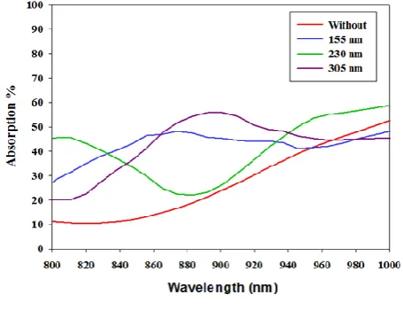
Figure 5. Absorption in infrared
The highest peaks in the range of infrared happened at position 305 nm with wavelength 900 nm which was about
55.92% as shown in Figure 5. The highest value of absorption mostly occurs at position 305 nm in the range from 100 nm to 1000 nm. This is due to the position that was very near with top surface.
4. Reflection for Gold Nanoparticle of
Plasmonic Solar cell
The reflection of plasmonic solar cell with different position was investigated in the same range of wavelength when investigated the reflection. However, the simulation results showed that without gold nanoparticle structure has highest reflection compared with gold nanoparticle as shown in Figure 6. The reflection starts with lowest value at ultraviolet light and the pattern of graph was quite similarly in with and without nanoparticles at the range 100 nm until 690 nm same like absorption pattern of graph. Starting from 690 nm, the value of reflection was showed different pattern between all positions.
Figure 6. Reflection of light for gold nanoparticle inside plasmonic solar cell
Based on Figure 6, the highest peak of reflection was observed in the range of infrared at about 74.33% with wavelength 811 nm and the second highest peak of reflection happened at visible light at about 71.89% with wavelength 595 nm. Both of these highest peaks of reflection occur when plasmonic solar cell doesn’t use gold nanoparticle.
5. Transmission for Gold Nanoparticle
of Plasmonic Solar Cell
[image:3.595.60.285.197.366.2] [image:3.595.308.531.328.489.2] [image:3.595.59.287.538.713.2]Figure 7. Transmission of light for gold nanoparticle inside plasmonic solar cell
6. ART for Gold Nanoparticle of
Plasmonic Solar Cell in Position 305
nm
Position of gold nanoparticle at 305 nm was taken to analyze the absorption, reflection and transmission (ART) in plasmonic solar cell. This position was analyzed due to their highest value in absorption and low reflection and transmission compared with other position of gold nanoparticle and without gold nanoparticle. The good absorption in plasmonic solar cell can be achieved when it has low reflection and transmission of light.
Figure 8. Absorption, reflection and transmission (ART) in position 305 nm of plasmonic solar cell
As illustrated in Figure 8, the pattern of graph for absorption and reflection is quite similar but opposite between each other. This pattern shows that the absorption will be higher when reflection is lower. On the other hand, the transmission pattern is shown in gradual increase and it has lowest percentage value compared with absorption and reflection.
7. Electric Field Intensity for Gold
Nanoparticle of Plasmonic Solar Cell
The electric field intensity for gold nanoparticle in plasmonic solar cell at different position was analyzed to show how the nanoparticle can produce the highest electric fields intensity in plasmonic solar cell.
Figure 9. Electric field intensity in normal for different position of nanoparticle
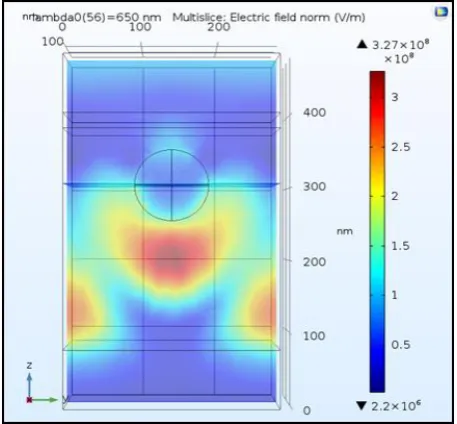
[image:4.595.59.286.78.246.2]Based on Figure 8, plasmonic solar cell without nanoparticle has shown the lowest electric field intensity compared to nanoparticle whereas, the highest peak electric fields intensity was observed at roughly 4.66 × 10⁻¹⁵ in position 305 nm with wavelength 650 nm. This high value is seen at the range of visible light which mostly solar cell used this range to convert electricity that can provide high efficiency in plasmonic solar cells. The simulation results for electric field intensity at position 305 nm with wavelength 650 nm can be seen in 2D structure using multislice as shown in Figure 10 and Figure 11.
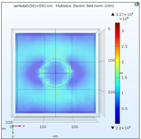
[image:4.595.310.530.167.338.2] [image:4.595.61.285.459.628.2] [image:4.595.307.536.510.722.2]Figure 11. Top view structure for electric field in normal at wavelength 650 nm
As illustrated in Figure 10 and Figure 11, the intensity of electric field for 650 nm at surrounding of gold nanoparticle area was highest which has maximum 3.27 × 10⁸ V/m. The electric field intensity more focused at bottom of gold nanoparticle in silicon layer which was efficient in generating the electricity in plasmonic solar cell.
8. Conclusions
In summary, gold nanoparticle is demonstrated using numerical simulation in various positions which are 115 nm, 230 nm and 305 nm that embedded into silicon layer of plasmonic solar cell. The optical absorption, reflection and transmission percentage were analyzed in different position of gold nanoparticle in the range from 100 nm to 1000 nm. In this range, the numerical result for absorption without gold nanoparticle was observed as the lowest absorption compared with gold nanoparticle and it starts with high value at ultraviolet light. At the range of visible spectrum, the highest peak of absorption occurs in position 155 nm with wavelength 667 nm at about 62.59%. While, the highest peaks in the range of infrared happened at position 305 nm at about 55.92% with wavelength 901 nm. The position of 305 nm was taken to analyze due to their highest value in absorption and low reflection and transmission compared without gold nanoparticle and other position of gold nanoparticle. The simulation results for this position show that the pattern of graph for absorption and reflection is quite similar but opposite between each other. In contrast, the transmission pattern is shown in gradual increase and it has lowest percentage value compared with absorption and reflection. Lastly, the high value for electric field intensity was occurring at position
305 nm in visible range. This overall simulation results proved that at position 305 nm of gold nanoparticle which is near with top layer is more efficient to be used as a method to trap the light and enhance the absorption of light in plasmonic solar cell. Absorption is very important because when plasmonic solar cell has high absorption of light, more electricity can be generated. This study could be helpful for the design of plasmonic solar cell to be more interesting technologies in solar cell application. Silicon in plasmonic solar cell does not absorb light very well. For this reason, more light needs to be scattered across the surface in order to increase the absorption by correctly positioning the gold nanoparticle near the top surface.
Acknowledgements
This research work was fully sponsored by Universiti Tun Hussein Onn Malaysia under TIER 1 phase 1/2017 vot U901 and GPPS 2017 vot U973. We extend our special thanks to I-Math Sdn Bhd in providing the Comsol Multiphysics 5.3a software trial for the simulation.
REFERENCES
G. C. Righini, B. Boulard, F. Coccetti, F. Enrichi, M. Ferrari, [1]
A. Lukowiakf, S. Pelli, L. Zur, & A. Quandt. Light management in solar cells: Recent advances, International Conference on Transparent Optical Networks (ICTON), 1-6, 2017.
S. A. Choudhury, & M. H. Chowdhury. Use of plasmonic [2]
metal nanoparticles to increase the light absorption efficiency of thin-film solar cells, International Conference on Sustainable Energy Technologies (ICSET), 196-201, 2016.
R. Ohib, S. Y. Arnob, M. S. Ali, R. H. Sagor, & M. R. Amin. [3]
Metal nanoparticle enhanced light absorption in GaAs thin-film solar cell, Asia-Pacific Conference on Applied Electromagnetics (APACE), 89-93, 2016.
A. Elrashidi. Optical Absorption Enhancement of a-si: H [4]
Solar Cells using Plasmonic Nanoparticles and Nanoantennas, Materials Today: Proceedings, 4, S27-S35, 2017.
S. Castelletto, & A. Boretti. Noble metal nanoparticles in [5]
thin film solar cells. Nanoscience and Nanotechnology Letters, 5(1), 36-40, 2013.
F. Enderle, O. Dubbers, A. Plettl, & P. Ziemann. Controlled [6]
positioning of nanoparticles on a micrometer scale, Beilstein journal of nanotechnology, 3(1), 773-777, 2012.
N. M. Nasar, R. Abdul-Kahar, N. S. A. Hamzah, & F. E. Esa. [7]
Optical Absorption of Plasmonic Cylindrical Gold Nanoparticle in Hexagonal Geometry, International Journal of Engineering & Technology, 7, 269–270, 2018.
Chen, & G. Y. Liu. Precise positioning of nanoparticle on surface using scanning probe lithography, Nano Letter, 3(3), 389-395, 2013.
Z. Zhu, J. Sun, Z. Li, X. Yu, J. Zhao, & H. Dai. Tunable light [9]
absorption of Ag nanoparticles@ carbon sphere by the position control of Ag nanoparticles, Optik, 179, 831-836, 2019.
J. E. Jacak, &W. A. Jacak. Plasmonic Enhancement of Solar [10]
Cells Efficiency: Material Dependence in Semiconductor Metallic Surface Nano-Modification. In Plasmonic. IntechOpen, 2018.
M. H. Muhammad, M. F. O. Hameed & S. S. A. Obayya. [11]
Absorption Enhancement in Hexagonal Plasmonic Solar Cell, Numerical Simulation of Optoelectronic Devices (NUSOD), 63-64, 2014.
M. Hu, J. Chen, Z. Y. Li, L. Au, G. V. Hartland, X. Li, M. [12]
Marquez, & Y. Xia. Gold nanostructures: engineering their plasmonic properties for biomedical applications, Chemical Society Reviews, 35(11), 1084-1094, 2016.
M. S. Hossain, R. Saidur, M. F. M. Sabri, Z. Said, & S. [13]
Hassani. Spotlight on available optical properties and models of nanofluids: A review, Renewable and Sustainable Energy Reviews, 43, 750-762, 2015.
J. Jung, K. Ha, J. Cho, S. Ahn, H. Park, S. Q. Hussain, M. [14]
Choi, & J. Yi. Enhancing light trapping properties of thin film solar cells by Plasmonic effect of silver Nanoparticles, Journal of nanoscience and nanotechnology, 13(12), 7860-7864, 2013.
O. Lehtikangas, T. Tarvainen, A. D. Kim, & S. R. Arridge. [15]
Finite element approximation of the radiative transport equation in a medium with piece-wise constant refractive index, Journal of Computational Physics, 282, 345–359, 2015.
A. D. Rakić, A. B. Djurišić, J. M. Elazar, & M. L. Majewski. [16]