..
I
REV -DESCRIPTION DATE APPROVED
A ORIGINAL ISSUE
B . REWRITTEN
-
-I
CENTURY DATA
,MODEL 140 FLOPPY DISK DRIVE
·INTERFACE SPECIFICATIONS
I I
1 ,
,
!
I ,
I
i
I
!
!
i
DRAWING NO. RE v.
J:J..
Century
Data
TITLE: SPECIFICATION, i
INTERFACE, MODEL 140 11651-001 B i
•
DRAWN BY CHECKED BY
SYSTEMS, INC. I
APPD. APFtD DATE PAGE 1 OF 35 !
Section 1.0 2.0 3.0 4.0 4.1 4.2 4.3 4.4 4.5 4.6 4.7 5.0 5.1 5.2 5.3 5.4 5.5 5.6 5.6.1 5.6.2 5.7 6.0 7.0 8.0 8.1 8.2
FORM F4500-230 9n3
TABLE OF CONTENTS
Title
SCOPE
RELATED DOCUMENTS
GENERAL DESCRIPTION
RELIABILITY
SERVICE LIFE
MEAN TIME BETWEEN FAILURE
MEAN TIME TO REPAIR
PREVENTIVE MAINTENANCE
RECOVERABLE READ ERROR RATE
NON-RECOVERABLE READ ERROR RATE
ACCESS POSITIONING ERROR RATE
ENVIRONMENTAL REQUIREMENTS
TEMPERATURE
RELATIVE HUMIDITY
SHOCK
VIBRATION
ALTITUDE
FLEXIBLE DISK ENVIRONMENT
TEMPERATURE
RELATIVE HUMIDITY
CLEANLINESS AND AIR FULTER
UNDERWRITER APPROVALS
OPERATOR CONTROL
POWER REQUIREMENTS
AC POWER
DC POWER
Page 5 5 5 5 5 6 6 6 6 6 7 7 7 7 7 7 8 8 8 8 8 9 9 10 -10 10
DRAWING NO.
11651-001
PAGE 2 OF
REV.
B
9.0 CABLE CONNECTIONS 10
9.1 AC POWER CABLE 10
9.1.1 PO PIN ASSIGNMENTS 11
9.2 DC/SIGNAL CABLE 11
9.2.1 PI PIN ASSIGNMENTS 12
9.2.2 INTERFACE SIGNAL DEFINITIONS 12
9.2.2.1 INPUT SIGNALS 13
9.2.2.2 OUTPUT SIGNALS 14
9. 2.4 INTERFACE CIRCUITS 16
9.2.4.1 RECEIVERS 16
9.2.4.2 DRIVERS 16
9.2.5 DC/SIGNAL CABLE PHYSICAL WIRING 17
9.2.5.1 DAISY CHAINED INTERFACE WIRING 19
9.2.5.2 RADIAL INTERFACE WIRING 23
9 .2 • 6 INTERFACE TIMING 24
9.2.6.1 TRACK POSITIONING 24
9.2.6.2 READ DATA TIMING 26
9.2.6.3 WRITE DATA TIMING 29.
10.0 IBM 3740 DATA FORMAT 30
11.0 POWER SEQUENCING 32
11.1 POWER-ON SEQUENCE 32
11.2 POWER-OFF SEQUENCE 32
12.0 PHYSICAL DIMENSIONS 32
13.0 RECOMMENDED MOUNTING 34
14.0 SUMMARY OF SPECIFICATIONS 35
DRAWING NO. REV.
11651-001 B
PAGE 3 OF 35
LIST OF ILLUSTRATIONS
Figure Title
1 OPERATOR CONTROL
2 CABLE LOCATIONS
3 RECEIVER SCHEMATIC
4 DRIVER SCHEMATIC
5 TERMINATOR SCHEMATIC
6 TRACK ACCESSING TIMING
7 RAW DATA TIMING
8 ONE SHOT TIMING
9 PLO TIMING
10 WRITE DATA TIMING
11 PHYSICAL DIMENSIONS
12 RECOMMENDED MOUNTING
FOAM F4500-230 9/73
9
10 16 16 18
25
27
27
29
29
33
34
DRAWING NO. REV.
11651-001 B
1.0 SCOPE
This specification has been prepared to meet the needs of the Original Equipment Manufacturer (OEM) who intends to use the
Model 140 Floppy Disk Drive as a component in his data storage
system. This document describes detailed interface information
required by the equipment designer.
2.0 RELATED DOCUMENTS
Model 140 Disk Drive Installation and Parts Manual. Model 140 Disk Drive Operation and Maintenance Manual. Century Data Packing and Shipping Specification.
3.0 GENERAL DESCRIPTION
The Century Data Model 140 Floppy Disk Drive is a third
generatio~ high speed, random access, disk storage unit which utilizes a flexible disk cartridge as the storage medium. Up to 3.20 million bits of data may be stored on the single
recording surface of the flexible disk. When utilizing the
IBM 3740 data format, 1.94 million bits of data may be recorded. The Model 140 Floppy Disk Drive features 48 tracks-per-inch and 3200 bits-per-inch technologies to provide media inter-changeability with the IBM 3740 series of data recording equip-ment.
Access time is 6 milliseconds track to track with 10 milli-seconds required after the final step for head stabilization. The flexible disk is rotated at 360 RPM yielding a data transfer rate of 250,000 bits-per-second.
The Model 140 contains features and options whereby a systems designer may incorporate the Model 140 into his data storage
system with a minimum of effort. Among these are a positive
pressurized media chamber, precise media registration, write
protect capability, sector outputs, and a choice of data outputs.
4.0 RELIABILITY
4.1 Service Life
The Model 140 Floppy Disk Drive is designed and constructed to
provide a useful life of
?
years or 35,000 hours, whicheveroccurs first, before a factory overhaul or replacement is
required. Repair or replacement of parts will be permitted
during the lifetime of the unit.
DRAWING NO. REV.
11651-001 B
PAGE 5 OF 35
4.2 Mean Time Between Failure (MTBF)
Following an initial period of 200 hours, MTBF shall exceed
5,000 hours. The following expression defines MTBF:
MTBF = Operating Hours
Number of Equipment Failures
Operating hours mean total "power-on" hours less any maintenance
time. Equipment failures mean any stoppage or substandard
performance of the unit because of equipment malfunction.
Equipment failure shall exclude downtime or substandard perfor-mance due to operator error, adverse environment, power failure,
or other failures not caused by the disk drive. To establish
a meaningful MTBF, operating hours must be greater than 2,500 hours and shall include all sites where the disk drives are used.
For the purpose of this specification, equipment failures are defined as those failures requiring repairs, adjustments or
replacements on an unscheduled basis, i.e., emergency ~
maintenance is required because of hardware failure or sub-standard performance.
4.3 Mean Time to Repair (MTTR)
MTTR shall be less than 0.5 hours, and is defined as the time required for an adequately trained and competent serviceman to diagnose and correct a malfunction.
4.4 Preventive Maintenance
The Model 140 Floppy Disk Drive does not require regular
preventive maintenance.
4.5 Recoverable Read Error Rate
Th~ recoverable read error rate shall be less than one error in
10 bits read. A recoverable read error is one which can be
recovered in ten or less attempts to read the record.
Errors attributed to the flexible disk will not be included in determining the recoverable read error rate.
4.6 Non-Recoverable Read Error Rate
The non-rec£~erable read error rate shall be less than one
error in 10 bits read. A non-recoverable read error is one
which remains after ten unsuccessful attempts to read the record.
DRAWING NO.
11651-001
REV.
B
PAGE 6 OF 35
Errors attributed to the flexible disk will not be included in determining the non-recoverable read error rate.
4.7 Access Positioning Error Rate
Provided proper interface timing requirements are followed, the
access posit~oning error rate shall be less than one position
error per 10 access positioning operations.
I 5.0 ENVIRONMENTAL REQUIREMENTS
The Model 140 Floppy Disk Drive will provide satisfactory performance when operated within the following environmental parameters.
5.1 Temperature
(a) Operating:
(b) Non-operating:
5.2 Relative Humidity
(a) Operating:
(b) Non-operating:
5.3 Shock
60°F to lOooF, maximum gradient of 20°F per hour.
-30°F to 140°F
20% to 80%, 78°F maximum wet bulb 5% to 98%, no condensation
Non-operating: The unit shall not suffer damage or fail to
perform as specified when subjected to 18 impact shocks of 5G's (+10%) consisting of 3 shocks in opposite directions along each of
3 mutually perpendicular axes. Each shock
impulse shall have a time duration of 11 (+1)
milliseconds.
-5.4 Vibration
(a) Operating: The unit shall withstand a peak
displace-ment of ±0.005 inch for the frequency range from 5 to 60Hz and +2G's for the range from 60 to 500Hz.
FORM F4500-230 9/73
(b) Non-operating: The unit shall withstand 1.5G's from 5
to 55Hz for four hours on each axis with a 20 minute frequency span (no external packaging or internal bracing allowed) .
DRAWING NO. REV.
11651-001 B
5.5 Altitude
(a)
(b)
Operating: Non-operating:
Mean sea level to 10,000 feet
1,000 feet below sea level to 15,000 feet above sea level.
5.6 Flexible Disk Environment
Flexible disks shall be in the same temperature and humidity environment as the disk drive for a minimum of 5 minutes prior to installation of the flexible disk into the disk drive.
5.6.1 Temperature
(a) Operating: 5QoF to l25°F, maximum gradient of
2QoF per hour.
(b) Non-operating: 50° F to l2~0 F
5.6.2 Relative Humidity
(a) Operating: 20% to 80%, 78°F maximum wet bulb
8% to 88%, 85°F maximum wet bulb
(b) Non-operating:
5.7 Cleanliness and Air Filter
FORM F4500-230 9n3
(a) Cleanliness: The Model 140 Floppy Disk Drive does not
normally require periodic cleaning of the
chassis or read/write head. Each flexible
disk contains a special wiping tissue
(b) Air filter:
within its protective jacket to remove and trap excess oxide or foreign debris from the surface of the flexible disk.
Should the read/write head require cleaning due to the continued use of a fully con-taminated flexible disk, the head should be cleaned using lintless gauze dampened with
91% isopropyl alcohol. After cleaning,
the head should be wiped with a clean, dry gauze to remove any residue left when
the alcohol evaporates.
The Model 140 is equipped with a positive
pressure air system. A fan located on
the spindle drive motor serves to draw air through a filter located at the rear of the unit and pass this air across the flexible
disk venting at the rear of the unit. The
function of this system i~ to control and
filter air within the unit in order to
DRAWING NO.
11651-001
PAGE 8 OF 35
REV.
6.0 UNDERWRITER APPROVALS
provide the highest possible reliability. The air system is in constant operation including during flexible disk removal and replacement.
Since the Model 140 will be used in numerous applications with varying
environmental conditions, a recommended air filter replacement schedule is not
provided. The systems designer or
main-tenance planner should be advised of the positive pressure system and take action appropriate to his particular application.
The Model 140 Floppy Disk Drive is UL and CSA recognized.
The systems designer should consult appropriate regulations as a part of implementing the Model 140 into his system.
7.0 OPERATOR CONTROL
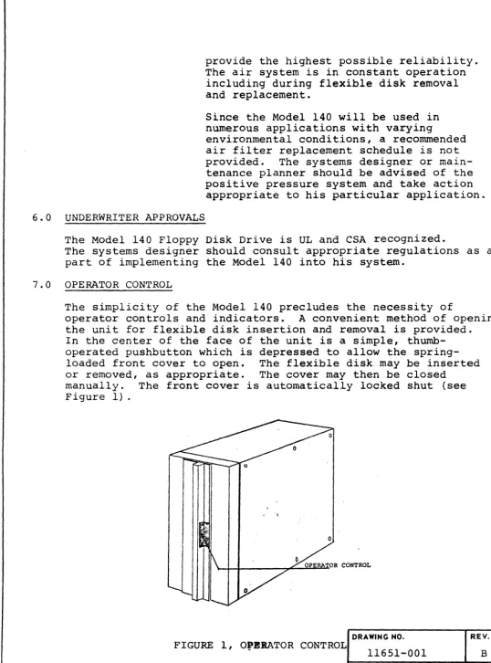
The simplicity of the Model 140 precludes the necessity of
operator controls and indicators. A convenient method of opening
the unit for flexible disk insertion and removal is provided. In the center of the face of the unit is a simple, thumb-operated pushbutton which is depressed to allow the
spring-loaded front cover to open. The flexible disk may be inserted
or removed, as appropriate. The cover may then be closed
manually. The front cover is automatically locked shut (see
Figure 1) .
I "
DRAWING NO. REV.
FIGURE 1, O,ERATOR CONTROL
11651-001 B
PAGE 9 OF 35
[image:9.624.59.597.37.763.2]8.0
8.1
8.2
POWER REQUIREMENTS
AC Power
( a) 50Hz = 100 VAC + 10%,
+0.5Hz 208 VAC +
-
10%,220 VAC + 10%,
240 VAC + 10%,
-(b) 60Hz
=
100 VAC + 10%,+0.5Hz 115 VAC + 10%,
208 VAC + 10%,
230 VAC + 10%,
-DC POWER
+5VDC + 2% @ 1.5 amps
+24VDC + 5% @ 1.0 amp
single phase single phase single phase single phase
single phase single phase single phase single phase
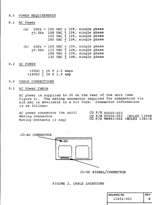
9.0 CABLE CONNECTIONS
9.1 AC Power Cable
AC power is supplied to JO on the rear of the unit (see
Figure 2). The mating connector required for connection via
#18 AWG is-available in
a
kit form.": _Connector information·is as follows:
AC power connector (on unit) Mating connector
Mating~contacts (3 req)
JO-AC CONNECTOR
DO
CD PIN 90605-003
CD PIN 90606-003 ,(MOLEX -139-6R),
CD PIN %441-002 (MOLEX 1381-AT ...
---
JI-DC SIGNAL/CONNECTOR FIGURE 2, CABLE LOCATIONSDRAWING NO. REV.
11651-001 B
PAGE 10 OF 35
[image:10.620.55.590.48.765.2]o
c
o
9.1.1 PO Pin Assignments
9.2
Phase to Phase PO-l - 230 VAC
PO-2 - chassis ground
PO-3 - 230 VAC
Phase to Neutral PO-l - 115 VAC
PO-2 - chassis ground
PO-3 - 115 VAC return
-NOTE-With phase to phase systems, pins 1
and 3 should be fused. With phase to
neutral systems, pin 1 should be fused.
For UL approval, the unit must draw its
power from the host system. All cable
grounds are brought together on the drive. PWB.
DC/Signal Cable
DC power, control information, and data are transmitted between
the control unit and the drive via the DC/Signal Cable. The
mat-ing connector required to interface with twisted pairs, returns
grounded, #24 or #26 AWG wire is available in kit form. Cable
twist should be approximately 30 twists per foot, with a maximum
cable length of 20 feet. While each drive's interface is
identi-cal, provisions have been made whereby each drive may be assigned a unique address and used in a bussed or daisy chained
configura-tion. This is accomplished by the use of a SELECT line which
enables communication between the Model 140 and its host
controller. Each drive contains the select function and may
be controlled individually in a bussed configuration by the use of unique SELECT lines built into the DC/Signal Cable.
Another unique line is READY. This line serves as an interrupt
to the controller and is intended to reduce controller overhead. This line is particularly useful during flexible disk changes. All other lines are gated by SELECT, including data transfer.
In a daisy chained configuration, a terminator PWB is required
for the last unit in the chain. In a radial configuration,
the terminator PWB is not required unless the DC/Signal Cable
length exceeds 5 feet. Refer to paragraph 9.2.5 for physical
wiring details. The DC/Signal Cable is connected to J-l
located at the rear of the unit (refer to Figure 2). Connector
information is as follows:
DRAWING NO. 11651-001
PAGE 11 OF
REV.
B
35
o
c
. 0
9.2.1 9.2.2 PIDC/Signal connector (on unit) Mating connector
Crimp tool Extract tool Strain relief
Pin Assisnments
§iqnal
Pin Ground PinP-2 P-l
P-4 P-3
P-6 P-5
P-8 P-7
P-lO P-9
P-12 P-ll
P-14 P-13
P-16 P-15
P-18 P-17
P-20 P-l9
P-22 P-21
P-24 P-23
P-26 P-25
P-28 P-27
P-30 P-29
P-32 P-31
P-34 P-33
P-36 P-35
P-38 P-37
P-40 P-39
Interface Signal Definitions
CD PIN 95359-040 CD PIN 97421-044
ITT Common CCT-UCB ITT Common CET-UB
CD~~/N97230-040
Signal Nomenclature
+5VDC +5VDC DIRECTION STEP/ +24V +24V +24V SELBCT/ TRACK 00/ HEAD LOAD/ READY/
ABOVE TRACK 43/ INDEX/
SECTOR/
WRITE PROTECTED/ WRITE DATA!
WRITE ENABLE/ READ DATA
READ CLOCK (OR RAW DAT~
PLO SYNC/
All interface lines are low active (OV) unless otherwise
specified. Driver and receiver circuits used within the
Model 140 are DTL and TTL. Controller driver and~receiver
circuits must provide equivalent voltage and impedance levels for proper signal transmission.
LOW - refers to the low voltage condition commonly encountered with TTL and DTL logic, and corresponds to a voltage in
the range of 0.0 V to 0.4
v.
HIGH - re fers to the high voltage condi tion conunonly encoun tered with TTL and DTL logic, and corresponds to a voltage in
the range of 2.2 V to 5.5 V .
DRAWING NO. REV.
11651-001 B
PAGE 12 OF 35
c
9.2.2.1 Input Signals Signal NameSELECT/
WRITE ENABLE/
WRITE DATA/
ABOVE TRACK 43/
c
STEP/
DIRECTION
o
FORM F4500·230 9n3
Definition
A unique signal used to enable communication between a disk drive and its controller. This line must be low (OV) to be active.
Enables recording of data on the flexible
disk. This line must be low (OV) to be
active. When this line is high (5V),
reading from the flexible disk is enabled.
This line carries low active (OV) pulses representing data to be recorded on the
flexible disk. Write current reverses
direction on the trailing edge of each pulse. Pulses must be 0.2 to 1.5 microseconds
wide with a maximum repetition rate of 2.0 microseconds.
This line is used to control write current amplitude, guaranteeing IBM 3740 media
interchangeability. This line must be high
(5V) when recording on tracks 0 through 43, and low (OV) when recording on tracks 44
through 76. ABOVE TRACK 43 must be stabilized
10 microseconds before activating WRITE ENABLE.
This line is used in conjunction with
DIRECTION and is used to cause the read/write
head to be moved from track to track. A
low pulse (OV) of 2U8 to 4MS causes
the head to move one track in the direction
specified by the DIRECTION line. Maximum
step rate is 167 steps per second (6 milliseconds per step) .
This line is used in conjunction with STEP to cause the read/write head to be moved
from track to track. When this line is
high (5V) , direction is IN (higher numbered
tracks). When this line is low (OV) ,
direc-tion is OUT (lower numbered tracks) .
This line must be stable 100 nanoseconds
minimum before activating STEP and remain in '. the appropriate state tor the duration of
the step period.
DRAWING NO.
11651-001
PAGE 13
REV.
B
HEAD LOAD/
o
PLO SYNC/
~.2.2.2 Output Signals
Signal Name
READ DATA
(:
READ CLOCK/
o
CDS 41100-23 4/71
This line is used to move the flexible disk against the read/write head for data
re-cording or retrieval. This line must be low
(OV) to be active. A 16 millisecond delay
is required after activating this line prior •
to commencing data transfers to allow for media loading.
A low level (OV) pulse 12 microseconds wide will cause the PLO data separator to
sync to preamble O's for data tracking.
Definition
This line transmits read data to the
control-ler. Exact line definition and timing
characteristics depend on the data separator
present within the drive. When no data separ- I
ator is present within the drive, this line has no function.
Wi~h Standard One-Shot Separator
This line is a NRZ data line with the one
shot separator. The level of the line
represents data. A one bit is represented
by a low (OV) level, and a zero bit is
represented by a high (5V) level. The
READ CLOCK line is used to clock data into
the controller. Refer to paragraph 9.2.5.2
for timing characteristics.
With Optional PLO Data Separator
This line outputs data pulses with the PLO
separator. A one bit is represented by an
800 nanosecond low (OV) level pulse. A
zero bit is represented by the absence
of a pulse. The READ CLOCK line is used to
clock data into the controller. Refer
to paragraph 9.2.5.2 for timing character-istics.
Exact meaning and timing characteristics of this line depend on the data separator used within the drive.
With No Data Separator
When no data separator is used within the
DRAWING NO. REV.
11651-001 B
INDEX/
TRACK 00/
READY/
SECTOR/
cos 4500 -23 417'
drive, this line outputs unseparated data
(clocks and data). This output is provided
for the systems designer who desires to use his own encloding scheme or provide data
separation in the controller. This output
may be used to enable detection of IBM 3740-type address marks by the controller.
A modified one-shot decoder with a missing
pulse detector will allow detection of
3740 address marks. Each flux reversal read
from the disk is output as a 300 + 100
nanosecond wide low (OV) pulse.
With One-Shot Separator
This line will output 300 + 100 nanosecond
wide low (OV) pulses representing separated
clocks. The trailing edge of these pulses
are used to strobe the READ DATA line into the controller.
With PLO Separator
This line will output 800 nanosecond wide
low (OV) pulses representing separated clocks. These pulses occur simultaneously with
pulses occurring on the READ DATA line.
The leading edge of a 450 microsecond wide low (OV) pulse on this line represents the
beginning of track. This pulse occurs once
per revolution of the flexible disk.
When this line is low (OV) , the read/write
head is positioned over track 00. This line
is intended as a head position reference. When this line is active, the stepper motor drive circuits are inhibited from further outward movement.
A low level (OV) on this line indicates that
the flexible disk is up to speed. This line
is not gated by SELECT and is thus a unique line:- This line serves as an interrupt to the controller and is particularly useful during flexible disk changes.
Low level (OV) pulses on this line represent
sector marks. Sector pulses are 1
milli-second wide.
DRAWING NO. REV.
11651-001 B
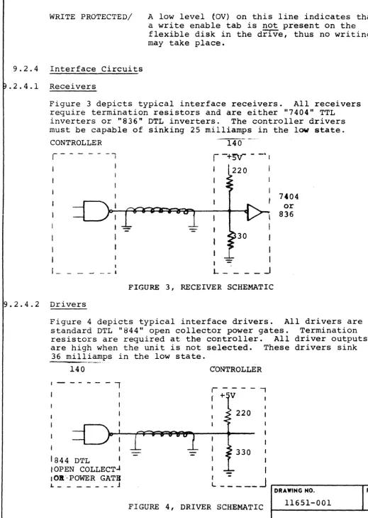
WRITE PROTECTED/ A low level (OV) on this line indicates that a write enable tab is not present on the flexible disk in the drIVe, thus no writing may take place.
9.2.4 Interface Circuits
.2.4.1 Receivers
Figure 3 depicts typical interface receivers. All receivers
require termination resistors and are either "7404" TTL inverters or "836" DTL inverters. The controller drivers
must be capable of sinking 25 milliamps in the low state.
CONTROLLER
1- _ _ -'
9.2.4.2 Drivers
l _ _ 1
140
r
-+sv- -
-"I30
I -:
L _ _
I
l
I
f
I I
_.J
FIGURE 3, RECEIVER SCHEMATIC
7404 or 836
Figure 4 depicts typical interface drivers. All drivers are
standard DTL "844" open collector power gates. Termination
resistors are required at the controller. All driver outputs
are high when the unit is not selected. These drivers sink
36 milliamps in the low state.
I
I
140
-,
1844 DTL I
,OPEN COLLECT~
I OIl"POWER GATIC L _ _ _ _ _ _ _ J
CONTROLLER
220
330 I
I
I I
I
-L _ _ _ _ _
J
DRAWING NO. REV.
FIGURE 4, DRIVER SCHEMATIC 11651-001 B
PAGE 16 OF 35
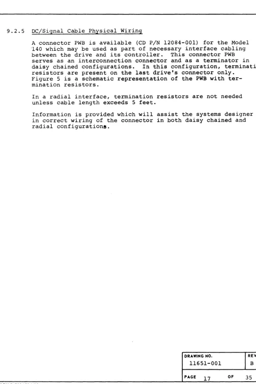
[image:16.623.57.576.41.770.2]9.2.5 DC/Signal Cable Physical Wiring
A connector PWB is available (CD PIN 12084-001) for the Model '140 which may be used as part of necessary interface cabling
between the drive and its controller. This connector PWB
serves as an interconnection connector and as a terminator in
daisy chained configurations. In this configuration, termination
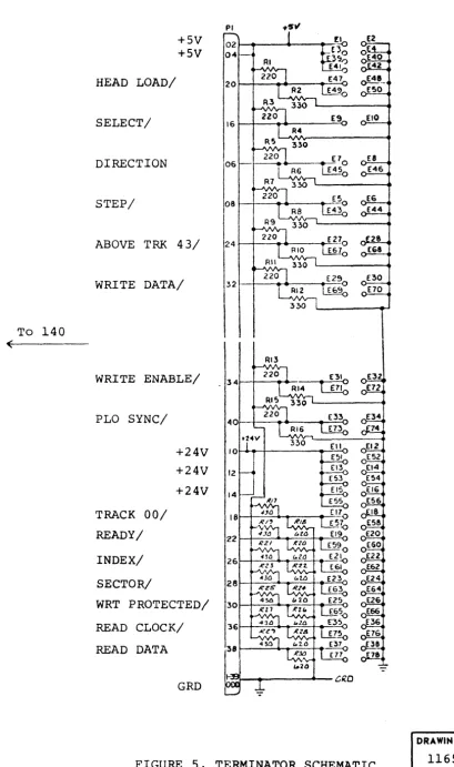
resistors are present on the last drive's connector only. Figure 5 is a schematic representation of the PWB with ter-mination resistors.
In a radial interface, termination resistors are not needed unless cable length exceeds 5 feet.
Information is provided which will assist the systems designer in correct wiring of the connector in both daisy chained and radial configurationa.
FORM F4500-230 9173
DRAWING NO.
11651-001
PAGE 17
REV.
B
[image:17.618.61.582.4.785.2]To 140
(
FORM F4500-230 Sn3
RI3
WRITE ENABLE/ 34~+---~----~~
PLO SYNC/ 40
+24V 10
+24V 12
+24V 14
TRACK 00/ 18
READY/ 22
INDEX/ 26
SECTOR/ 28
WRT PROTECTED/ 30
READ CLOCK/ 36
READ DATA 38 cJ:].8
7&
t.20
0(,0
GRD
FIGURE 5, TERMINATOR SCHEMATIC
-=-To Controller
)
DRAWING NO.
11651-001
REV.
B
[image:18.620.70.480.59.751.2]9.2.5.1 Daisy Chained Interface Wiring
All connector PWB's except the end drive should be wired as desc:r:ibed.
Definitions:
IN - a signal or power arriving at the drive's input
interface.
OUT - a signal being bussed to the next drive's input
interface.
UNIQUE - a signal not bussed
BUSS IN - a signal arriving at the drive or controller from
the preceeding drive (signals being bussed to the controller) .
BUSS OUT - a signal being sent from a drive towards the controller
(continued on next page)
DRAWING NO. REV.
11651-001 B
PAGE 19 OF 35
E 1 +5V (IN) ~ 2 TIiP GND (El)
E 3 +5V (IN) E 4 TWP GND (E3)
E 5 STEP (IN) E 6 TWP GND (ES)
_.
E 7 DIRECTION (IN) E 8 TWP GND (E7)E 9 SELECT (IN, UNIQUE) EIO TWP GND (E9)
Ell +24V (IN) E12 TWP GND (Ell)
E13 +24V (IN) E14 TWP GND (E13)
E15 +24V (IN) E16 TWP GND (ElS)
E17 TRACK 00 (BUSS OUT) E18 TWP GND (El7)
E19 READY (OUT, UNIQUE) E20 TWP GND (E19 )
E21 INDEX (BUSS OUT) E22 TWP GND (E21)
E23 SECTOR (BUSS OUT) E24 TWP GND (E23)
E25 WRITE PROTECTED (BUSS OUT) E26 TWP GND (E2S)
E27 ABOVE TRK 43 (IN) E28 TWP GND (E27 )
E29 WRT DATA (IN) E30 TWP GND (E29 )
E31 WRT ENABLE ( IN) E32 TWP GND (E31)
E33 PLO SYNC (IN) E34 TWP GND (E33)
E35 READ CLOCK (BUSS OUT) E36 TWP GND (E35)
E37 READ DATA (BUSS OUT) E38 TWP GND (E37 )
E39 +SV (OUT) E40 TWP GND (E39 )
E41 +5V (OUT) E42 TWP GND (E41)
E43 STEP (OUT) E44 TWP GND (E43)
E45 DIRECTION (OUT) E46 TWP GND (E45)
E47 HEAD LOAD ( IN) E48 TWP GND (E47)
E49 HEAD LOAD (OUT) E50 TWP GND (E49 )
ESI +24V (OUT) ES2 TWP GND (ES1)
ES3 +24V (OUT) E54 TWP GND (ES3)
E55 +24V (OUT) E56 TWP GND (ESS)
ES7 TRACK 00 (BUSS IN) E58 TWP GND (ES7)
ES9 NOT USED E60 NOT USED
E61 INDEX (BUSS IN) E62 TWP GND (E61)
E63 SECTOR (BUSS IN) E64 TWP GND (E63)
E65 WRITE PROTECTED (BUSS IN) E66 TWP GND (E6S)
E67 ABOVE TRK 43 (OUT) E68 TWP GND (E67)
E69 WRT DATA (OUT) E70 TWP GND (E69)
E71 WRT ENABLE (OUT) E72 TWP GND (E71)
E73 PLO SYNC (OUT) E74 TWP GND (E73)
E75 READ CLOCK (BUSS IN) E76 TWP GND (E7S)
E77 READ DATA (BUSS IN) E78 TWP GND (E77)
DRAWING NO. REV.
11651-001 B
PAGE 20 OF 35
END DRIVE PWB CONNECTOR WIRING
E 1 +SV (IN) E 2 TWP GND (El)
E 3 +5V (IN) E 4 TWP GND (E3 )
E 5 STEP (IN) E 6 TWP GND (E5)
E 7 DIRECTION (IN) E 8
rrwp
GND (E7)E 9 SELECT (IN,UNIQUE) ElO TWP GND (E9)
Ell +24V (IN) El2 TWP GND (Ell)
E13 +24V (IN) El4 TWP GND (E13)
E15 +24V (IN) E16 TWP GND (EI5)
E17 TRACK 00 (BUSS OUT) E18 TWP GND (E17)
E19 READY (OUT,UNIQUE) E20 TWP GND (EI9)
E21 INDEX (BUSS OUT) E22 TWP GND (E21)
E23 SECTOR (BUSS OUT) E24 TWP GND (E23)
E25 WRITE PROTECTED (BUSS OUT) E26 TWP GND (E25)
E27 ABOVE TRK 43 (IN) E28 TWP GND (E27)
E29 WRT DATA (IN) E30 TWP GND (E29)
E31 WRT ENABLE ( IN) E32 TWP GND (E31)
E33 PLO SYNC (IN) E34 TWP GND (E33)
E35 READ CLOCK (BUSS OUT) E36 TWP GND (E35)
E37 READ DATA (BUSS OUT) E38 TWP GND (E37)
E39 FAO
E41 FA2
E43 FA4
E45 FA6
E47 HEAD LOAD (IN) FA8 TWP GND (E47)
E49 ESO
E51 E52
E53 E54
E55 E56
E57 ES8
E59 E60
E61 El52
E63 E64
E65 E66
E67 E68
EG9 E70
E71 E72
E73 E74
E75 E76
E77 E78
DRAWING NO. REV.
11651-001 B
PAGE 21 OF 35
DAISY CHAIN EXAMPLE
WRT CLK
ontroller
INDEX
ontroller
&
ontrol1er
ontro11er
~, • \C.
&.
= TerminatorFORM F4600-230 9n3
t ;
+5
Controller to Drive Buss
Drive Buss to Controller
Ready (Unique)
~ Select (Unique)
po
,.1"
DRAWING NO.
11651-001
PAGE 22
REV.
B
9.2.5.2 Kadial Interface Wiring
IN - Signal or power coming from controller to drive.
OUT - Signal going from drive to controller.
E 1 +5V (IN) E 2 TWP GND (E1)
3 +5V (IN) 4 TWP GND (E3)
5 STEP (IN) 6 TWP GND (E5)
7 DIRECTION (IN) 8 TWP GND (E7)
9 SELECT ( IN) 10 TWP GND (E9 )
11 +24V (IN) 12 TWP GND (Ell)
13 +24V ( IN) 14 TWP GND (E13)
15 +24V (IN) 16 TWP GND (E15)
17 TRACK 00 (OUT) 18 TWP GND (E17)
19 READY (OUT) 20 TWP GND (E19)
21 INDEX (OUT) 22 TWI? GND (E21)
23 SECTOR (OUT) 24 TWP GND (E23)
25 WRITE PROTECTED(OUT) 26 TWP GND (E25)
27 ABOVE TRK 43 (IN) 28 TWP GND (E27)
29 WRT DATA (IN) 30 TWP GND (E29)
31 WRT ENABLE ( IN) 32 TWP GND (E31)
33 PLO SYNC (IN) 34 TWP GND (E33)
35 READ CLOCK (OUT) 36 TWP GND (E35)
37 READ DATA (OUT) 38 TWP GND (E37)
39 40
41 42
43 44
45 46
47 HEAD LOAD (IN) 48 TWP GND (E47)
49 50
51 52
53 54
55 56
57 58
59 60
61 62
63 64
65 66
67 68
69 70
71 72
73 74
75 76
77 78
DRAWING NO. REV.
11651-001 B
PAGE 23 OF 35
9.2.6 Interface Timing
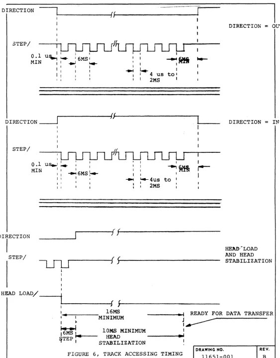
9.2.6.1 Track Positioning
Track positioning is accomplished by using interface lines
DIRECTION and STEP. The DIRECTION line must be set to the
proper level and be stable 100 nanoseconds minimum before the leading edge of STEP.
Head positioning should be accomplished by activating the STEP line at 167 pulses per second with one resultant head
position change per pulse. 10 milliseconds of head stabilizatior
time must be provided for after the last step prior to pro-ceeding with data transfer.
If a data transfer is to commence upon locating the desired track, i t is recommended that the head be loaded by activating the HEAD LOAD line at the same time as issuing the last step
pulse. Thus, the 16 millisecond time required to move the
media against the head coincides with the time required for stepping the last track and mechanical stabilization of the
head. By using this method, only one time-out is required in
the controller (16 milliseconds) and head loading is not a factor in latency.
Should an access position error occur, a reference may be established by either reading the track header or by stepping the head out until the TRACK 00 line becomes active.
DRAWING NO.
11651-001
REV.
B
PAGE 24 OF 35
DIRECTION
"
_______________
~(~(---~- II
STEP/
I I I I
0.1 u~ 1.4- I 6MS I
MIN I -.J ~
I I
I I
I
~i'1i
...
I
,
,
~ ~ I
I 4 us to'
I I I 2MS I
---~(~{---I
,.. JI
DIRECTION _ _ _
STEP/
STEP/
I
0.1
us..'t4r
I IMIN
::....!
6MSt--I 1 , I I I I
I I
I
....,~
I
~4us to I : 2MS
I
,--I
---~( ~/---) J
s
HEAD LOAD/ _ _ --+
~---~f
,~---DIRECTION = OU~
DIRECTION = IN
HEAO·-LOAD AND HEAD
STABILIZATION
'
...
I I
16MS
MINIMUM ________ ~.~I READY FOR DATA TRANSFER
FORM F4500-230 gn3
I '"
~
16MS ...
'---~TEP I
J
t
10MS MINIMUM I
HEAD
---~-~
STABILIZATION '
FIGURE 6, TRACK ACCESSING TIMING DRAWING NO.
11651-001
PAGE 25 OF 35
REV.
[image:25.617.49.612.23.742.2]9.2.6.2 Read Data Timing
Read data is transferred between the control unit and the Model
140 in a serial fashion. The organization of data and data
storage capacity of the flexible disk are dependent on the format used to record information.
A feature of the Century Data Model 140 Floppy Disk Drive
is its universal read circuits. While the expected recording
method is double frequency (FM) , a systems designer may specify
no data separator with the drive and use the READ CLOCK output
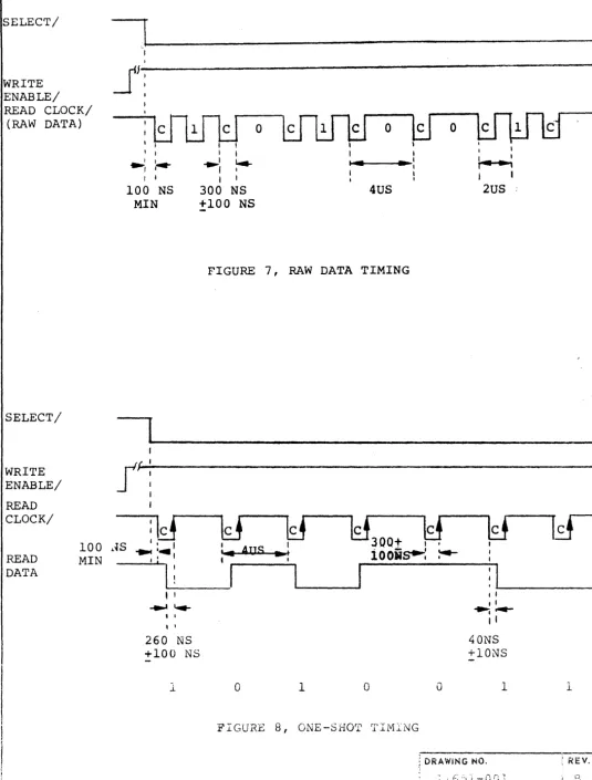
which would represent unseparated data and clocks to enable the use of another recording method which may be either more efficient or result in a higher throughput (see Figure 7).
For those applications which do not use the IBM 3740-type address marks, the standard one-shot data separator provides a READ CLOCK output which is used to strobe the status of the
READ DATA line into the controller. Thus, READ CLOCK becomes
separated clock and READ DATA becomes separated data (see
Figure 8).
For the systems designer who desires IBM media compatibility,
an optional PLO Data Separator option is offered. This circuit
ensures the highest data integrity in addition to its ability to enable detection of missing clocks as used with IBM 3740
address marks. The circuits are designed so that both outputs
coincide. During address mark detection, the PLO remains in
sync during the bit cell time in which the missing clock
is absent. READ DATA active with READ CLOCK being false
sig-nifies that a byte is being read in which a clock pulse is
missing. The systems designer simply has to decode the
data pattern of that associated pyte to determine which
type of address mark has been read (see Figure 9) .
For clarity, each of the read data outputs will be depicted along with appropriate timing details (see Figures 7, 8 & 9).
DRAWING NO. REV.
11651-001 B
PAGE 26 OF 35
SELECT/
WRITE ENABLE/ READ CLOCK/
(RAW DATA)
SELECT/
WRITE ENABLE/
READ CLOCK/
READ DATA
100 MIN
I
,
I
JI:
I
,
I 1 t, I I I I I I
I
:
...
~I ~.-
..
:
' I~, r I ~
I I I I I I I I
100 NS 300 NS 4US 2US :
MIN +100 NS
, I
...
~, I , I
260 NS +100 NS
1.
FIGURE 7, RAW DATA TIMING
lcl
I I
' . . AUS .... '
t ,
~JQQt ~
i
0oils---:
:--~
I: .... 1 _ _ _ _ _ _ _ 1
o
1o
FIGURE 8, ONE-SHOT TIMING
o
I I , I
~
...
II
40NS +lONS
1
DRAWiNG NO.
?ACi: 27
1
: REV.
!
i .
B
[image:27.623.69.605.41.747.2]SELECT/
I
I -J~J
WRITE
If!
ENABLE/
If
I
PLO SYNC/
-
I'!LJ;
US MIN{
,
: . 12
I ,
READ CLOCK/
-
~ ' .... 100 NS MIN,
112
~JJ
:t:LF
!J
us
W
-LJlJL
READ DATA --,MIN ~ 800 NS I - ,
, I
f~
800 NS
[image:28.626.61.595.50.748.2]-0 0 0 0 0 1 1
FIGURE 9, PLO TIMING
DRAWING NO. REV.
11651-001 B
PAGE 28 OF 35
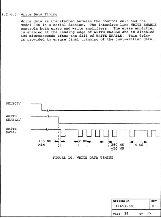
9.2.6.3 Write Data Timing
SELECT/
Write data is transferred between the control unit and the
Model 140 in a serial fashion. The interface line WRITE ENABLE
controls both erase and write amplifiers. The erase amplifier
is enabled at the leading edge of WRITE ENABLE and is disabled
600 microseconds after the fall of WRITE ENABLE. This delay
is provided to ensure final trimming of the just-written data.
~J~---I
WRITE
ENABLE/ - - -...
II-J--WRITE DATA/
CDS 4800-23 4/71
I I
I "';2 U~
I I J I
100 NS ...
:----MIN I •
I I
I I I ,
..,
...
I I 250 NS
I
+50 NS
I
I I
. . ~I
4 US • I
FIGURE 10, WRITE DATA TIMING
DRAWING NO.
11651-001
PAGE 29 OF 35
REV.
[image:29.617.64.606.49.780.2]10.0 IBM 3740 DATA FORMAT
Information provided here is provided as an overview of the
3740 data format. Track 00 contains Data Set Labels which
contain descriptive information regarding the sectors of data
located on tracks 01 through 76. These sectors are referred
to as Data Sets. A data set may contain one or more sectors
and may occupy one or more flexible disks. The actual length
of a data set is defined by the appropriate data set label in
track 00. For detailed data format and initialization
infor-mation, refer to IBM publication GA21-9l90.
DRAWING NO.
11651-001
REV.
B
PAGE 10 OF 35
"
o lJ
~
"
~
U1
o
o
~
(,J
o
to
:::J
(,J
"'V
~
a
m
w I-'
0
"'T1
w U1
IBM TRACK FORMAT
INOEX~
5 S
n
ADDRESS MARK 1 BYTE
--""'--.
TRACK
I I
I II
Sector 1I
Sector 2I
Sector JI { }
I Sector 241 Sector 25 1 Sector 26 1,
PREAMBLE I I PREAMBLE POSTAMBLE
,
....
-
-46 BYTES 32 BYTES 241 BYTES
IBM SECTOR FORMAT
ADDRESS MARK NEXT
TRACK/SECTOR 10 DATA SYNC CHECK SUM ADDRESS MARK
- - - - " " ' - --"-'-.
I
I
I
I
I
I I
I
I
~ ...
"----
~ ....ADDRESS GAP 1 DATA GAP 2
MARK
0 ... :;:u ~
FIELD
LENGTH
... ~
0'1 Z
- -
DATA BYTESU1 a EFFICIENCY = X 100%
... z ADDRESS MARK 1 BYTE TOTAL BYTES
I 0
TRACK/SECTOR ID 6 BYTES
0
0 GAP 1 17 BYTES
... 128
DATA SYNC 1 BYTE = - X 100% = 68%
DATA 128 BYTES 188
CHECK SUM 2 BYTES
GAP 2 JJ BYTES
:;:u
m TOTAL 188 BYTES
11.0 POWER SEQUENCING
11.1 Power-On Sequence
The following is the recommended power-on sequence for the Model 140 Disk Drive.
1. Set WRITE ENABLE to the false state (5V).
2. Apply AC a~d DC voltages in any sequence.
3. Set. the DIRECTION
-line
tothe
low state (OV) and apply a167 pulse-per~second pulse train to the STEP line.
Discontinu~ STEP pulses when the TRACK 00 line goes low
(OV) •
The Model 140 is now ready for flexible disk insertion (if not present) and operation.
11.2 Power-Off Sequence
The following is the recommended power-off sequence for the Model 140 Disk Drive.
1. Remove flexible disk.
2. Set WRITE ENABLE to the false state (5V).
3 . Remove AC and.
Pf--
vo 1 tages in any sequence.12.0 PHYSICAL DIMENSIONS
Figure 11 is provided as a reference for physical dimensions and is intended to assist in physical planning activities needed to incorporate the Model 140 into an OEM system.
DRAWING NO.
11651-001
PAGE 32 OF 35
FORM F4500-230 9n3
REV.
[image:32.617.52.564.37.756.2]14.25
.06
----.9c_
CDS 4800-23 4/71
f
4 .90
t
8.40
15.75
I
I
4 • 13--. -_____ . ,
I 3.92
14--- . 50-- J;J
~
!\
Approx 3.0 in. ---<I¥>.~ 0 - , - - - " " " ,
clearance for
V
Terminator, Cable --~~
and Exhaust
Air Exhaust
~\
I
1.00 / / 8-32 UNF-2B
- .--
~-,
~: -12.75
JIf~
f
Access cover_
6-32 UNC-2B
.25 Full thd.
L _____ - 6. 62
r -
.75~ --~
f
.25
JO - AC PWR
f\ir Inlet
.25 MIN FULL THD ~;§~~~==~~
[image:33.623.63.603.25.697.2]J1 - Signal & DC
FIGURE 11, PHYSICAL DIMENSIONS
~---~--~ DRAWING NO. REV.
11651-001 B
13.0 RECOMMENDED MOUNTING
(to be added)
FIGURE 12, RECOMMENDED MOUNTING
DRAWING NO. REV.
11651-001 B
PAGE 34 OF 33
[image:34.615.54.583.49.767.2]14.0 SUMMARY OF SPECIFICATIONS
STORAGE CAPACITY (UNFORMATTED)
PER FLEXIBLE DISK PER TRACK
IBM 3740 FORMAT
PER FLEXIBLE DISK PER TRACK
PER SECTOR
Number of Recording tracks Number of Read/Write Heads Recommended Coding Technique Bit Transfer Rate
Tracks-per-inch
Positioning Mechanism Positioning Time
Head Stabilization Time Head Load Time
Media
Rotational Speed
Motor Start Time (to ready)
Heat Dissipation Physical Dimensions
Width Height Depth
Weight
FORM F4500-230 9/73
3,208,128 bits/40l,016 bytes 41,664 bits/5,208 bytes
1,943,552 bits/242,944 bytes 26,624 bits/3328 bytes
1,024 bits/128 bytes 77
1, tunnel erase
Double Frequency (FM)
250,000 bits per second, nominal 48, center to center spacing
nominally 0.02083 inch; data
track width nominally. 0.0120 inch.
Stepping Motor, electrical detent 6 milliseconds, track-to-track 10 milliseconds
16 milliseconds
IBM 3740 Diskette or Century Data approved equivalent.
360 RPM
+
2.5%, 167 millisecondsper revolution 2 seconds maximum
540 BTU/hr
4.90 inches 8.40 inches
15.00 inches (add 3 inches for cable clearance)
16.00 pounds (18.00 pounds shipping weight)
DRAWING NO. 11651-001
PAGE 35: OF 35
REV.