© 2016, IRJET | Impact Factor value: 4.45 | ISO 9001:2008 Certified Journal
| Page 613
Lossless Huffman coding image compression implementation in spatial
domain by using advanced enhancement techniques
Ali Tariq Bhatti1, Dr. Jung H. Kim2
1,2Department of Electrical & Computer engineering 1,2NC A&T State University, Greensboro NC USA
1[email protected], [email protected], [email protected] 2[email protected]
Abstract: Images are basic source of information for almost all scenarios that degrades its quality both in visually and quantitatively way. Now–a-days, image compression is one of the demanding and vast researches because high Quality image requires larger bandwidth. Raw images need larger memory space.
In this paper, read an image of equal dimensional size (width and length) from MATLAB. Initialize and extract M-dimensional vectors or blocks from that image. However, initialize and design a code-book of size N for the compression. Quantize that image by using Huffman coding Algorithm to design a decode with table-lookup for reconstructing compressed image of different 8 scenarios. In this paper, several enhancement techniques were used for lossless Huffman coding in spatial domain such as Laplacian of Gaussian filter. Use laplacian of Gaussian filter to detect edges of lossless Huffman coding best quality compressed image(scenario#8) of block size of 16 and codebook size of 50. Implement the other enhancement techniques such as pseudo-coloring, bilateral filtering, and water marking for the lossless Huffman coding c based on best quality compressed image. Evaluate and analyze the performance metrics (compression ratio, bit-rate, PSNR, MSE and SNR) for reconstructed compress image with different scenarios depending on size of block and code-book. Once finally, check the execution time, how fast it computes that compressed image in one of the best scenarios. The main aim of Lossless Huffman coding using block and codebook size for image compression is to convert the image to a form better that is suited for analysis to human.
Keywords:- Huffman coding, Bilateral,
Pseudo-coloring, Laplacian filter, Water-marking
1. Image Compression
Image compression plays an impassive role in memory storage while getting a good quality compressed image. There are two types of compression such as Lossy and Lossless compression. Huffman coding is one of the efficient lossless compression techniques. It is a process for getting exact restoration of original data after
decompression. It has a lower Compression ratio In this paper, Huffman coding is used. Lossy compression is a process for getting not exact restoration of Original data after decompression. However, accuracy of re-construction is traded with efficiency of compression. It is mainly used for image data compression and decompression. It has a higher compression ratio. Lossy compression [1][2] can be seen in fast transmission of still images over the internet where the amount of error can be acceptable.
Enhancement techniques mainly fall into two broad categories: spatial domain methods and frequency domain methods [9].
Spatial domain techniques are more popular than the frequency domain methods because they are based on direct manipulation of pixels in an image such as logarithmic transforms, power law transforms, and histogram equalization. However, these pixel values are manipulated to achieve desired enhancement. But they usually enhance the whole image in a uniform manner which in many cases produces undesirable results [10].
2. Methodology
2.1 Huffman encoding and decoding process based on block size and codebook for image compression
Step 1- Reading MATLAB image 256x256
Step 2:- Converting 256x256 RGB image to Gray-scale level image
Step 3- Call a function that find the symbols for image Step 4- Call a function that calculate the probability of each symbol for image
Step 5- The probability of symbols should be arranged in DESCENDING order, so that the lower probabilities are merged. It is continued until it is deleted from the list [3] and replaced with an auxiliary symbol to represent the two original symbols.
Step6- In this step, the code words are achieved related to the corresponding symbols that result in a compressed data/image.
Step7- Huffman code words and final encoded Values (compressed data) all are to be concatenated.
© 2016, IRJET | Impact Factor value: 4.45 | ISO 9001:2008 Certified Journal
| Page 614
the frequencies that is also possible to write the Huffmantree on the output
Step9-Original image is reconstructed in spatial domain which is compressed and/or decompression is done by using Huffman decoding.
Step 10-Compressed image applied on Huffman coding to get the better quality image based on block and codebook size.
Step 11- Recovered reconstructed looks similar to original image.
Step 12: Implement Laplacian of Gaussian 5x5 filtering for lossless Huffman coding compressed image
Step 13: Implement Pseudo coloring for lossless Huffman coding compressed image
Step 14: Implement Bilateral filtering for lossless Huffman coding compressed image
[image:2.595.334.538.166.307.2]Step 15: Implement Water marking for lossless Huffman coding compressed image
Figure 1 Block diagram
2.2 Different scenarios
There are 8 different scenarios for image compression using lossless Huffman coding based on block and codebook size.
Figure 2 Original image (RGB to Gray-scale)
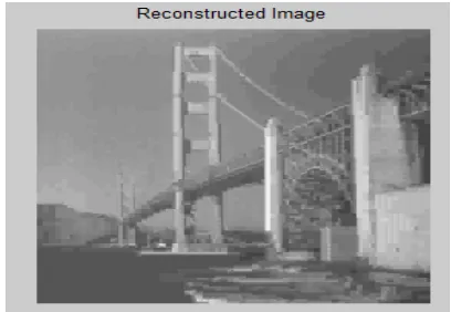
Scenario#8 Size of Block=M=16, and Size of Codebook=N=50 (16X50)
Figure 3 Reconstructed Image of 16X50
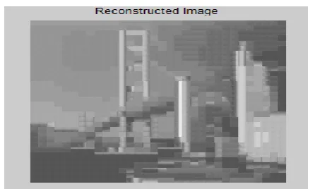
[image:2.595.53.265.340.501.2]Scenario#7 Size of Block=M=16, and Size of Codebook=N=25 (16X25)
Figure 4 Reconstructed Image of 16X25
[image:2.595.327.550.373.507.2]Scenario#6 Size of Block=M=64, and Size of Codebook=N=50 (64X50)
[image:2.595.55.258.614.755.2]© 2016, IRJET | Impact Factor value: 4.45 | ISO 9001:2008 Certified Journal
| Page 615
Scenario#5 Size of Block=M=64, and Size of [image:3.595.330.547.113.243.2]Codebook=N=25 (64X25)
Figure 6 Reconstructed Image of 64X25
Scenario#4 Size of Block=M=256, and Size of Codebook=N=50 (256X50)
Figure 7 Reconstructed Image of 256X50
[image:3.595.47.269.141.275.2]Scenario#3 Size of Block=M=256, and Size of Codebook=N=25 (256X25)
Figure 8 Reconstructed Image of 256X25
[image:3.595.325.547.308.439.2]Scenario#2 Size of Block=M=1024, and Size of Codebook=N=50 (1024X50)
Figure 9 Reconstructed Image of 1024X50
Scenario#1 Size of Block=M=1024, and Size of Codebook=N=25 (1024X25)
Figure 10 Reconstructed Image of 1024X25
Scenario#8 is the best one for better image quality which is block size of 16 and codebook size of 50
2.3 Performance Metrics
There are following performance metrics used for image compression of original and reconstructed image such as
(a) Bit Rate:
Bit Rate is defined as
(1)
(2)
The units for Bit Rate is bits/pixel.
(b) Compression Ratio:
[image:3.595.42.270.343.474.2] [image:3.595.49.265.547.688.2]© 2016, IRJET | Impact Factor value: 4.45 | ISO 9001:2008 Certified Journal
| Page 616
(3)
Compression Ratio is Unit-less.
(c) SNR:
SNR (Signal-To-Noise Ratio) is defined as
(4)
(d) MSE:
The Mean Square Error (MSE) is the error metric used to compare image quality. The MSE represents the cumulative squared error between the reconstructed(Yi) and the original image(Xi).
(5)
(e) PSNR
Peak Signal-to-Noise Ratio short as PSNR, is an engineering term for the ratio between the maximum possible power of a signal and the power of corrupting noise that affects the fidelity of its MSE representation.
(6)
Table 1 Performance metrics for lossless Huffman coding for first image
2.4 Probabilities for the best quality compressed image
In this paper, the block size of 16 and codebook size of 50 shows a better quality image than other scenarios . Therefore, the probabilities:
Probabilities for codebook size of 25 and 50 are as:
prob =
Columns 1 through 13
0.0031 0.0062 0.0092 0.0123 0.0154 0.0185 0.0215 0.0246 0.0277 0.0308 0.0338 0.0369 0.0400
Columns 14 through 25
0.0431 0.0462 0.0492 0.0523 0.0554 0.0585 0.0615 0.0646 0.0677 0.0708 0.0738 0.0769
ent = 4.3917
prob =
Columns 1 through 13
0.0008 0.0016 0.0024 0.0031 0.0039 0.0047 0.0055 0.0063 0.0071 0.0078 0.0086 0.0094 0.0102
Columns 14 through 26
0.0110 0.0118 0.0125 0.0133 0.0141 0.0149 0.0157 0.0165 0.0173 0.0180 0.0188 0.0196 0.0204
Columns 27 through 39
0.0212 0.0220 0.0227 0.0235 0.0243 0.0251 0.0259 0.0267 0.0275 0.0282 0.0290 0.0298 0.0306
Columns 40 through 50
0.0314 0.0322 0.0329 0.0337 0.0345 0.0353 0.0361 0.0369 0.0376 0.0384 0.0392
ent = 5.3790
3. Laplacian of Gaussian filter and Pseudo-coloring
© 2016, IRJET | Impact Factor value: 4.45 | ISO 9001:2008 Certified Journal
| Page 617
Figure 11 Laplacian filter for figure 3 [image:5.595.77.241.115.274.2]Pseudo-color is one of an attractive technique for use on digital image processing systems that is consequently used when a single channel of data is available.
[image:5.595.47.270.344.471.2]Figure 12 RGB intensity levels for figure 3
Figure 13 Plots of RGB over Gray levels for figure 3
Figure 14 Pseudo-colored image for figure 3
Figure 15 Pseudo coloring by sinusoids
[image:5.595.342.532.502.657.2] [image:5.595.36.278.511.720.2]© 2016, IRJET | Impact Factor value: 4.45 | ISO 9001:2008 Certified Journal
| Page 618
Figure 17 Laplacian filter for second image 16x504. Bilateral Filtering
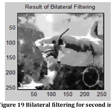
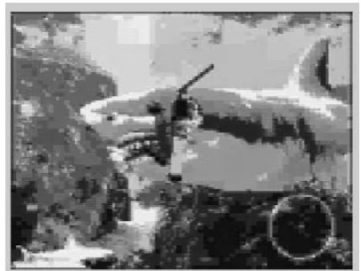
Tomasi and Manduchi [4] in 1998 introduced Bilateral filtering technique. Therefore, the acceleration of the computation speed is another interest for this type of filtering presented as the SUSAN filter and also Bethel neighborhood filter [5]. Therefore, [6][7][8] mentions that the bilateral filter is also be a theoretical origin which is known as Beltrami flow algorithm.
[image:6.595.67.247.112.279.2]Figure 18 Bilateral filtering for figure 3
Figure 19 Bilateral filtering for second image 16x50
5. Water marking for lossless Huffman coding
[image:6.595.336.538.415.550.2]Water marking is the process of inserting predefined patterns into multimedia data in such a way to minimize it’s quality degradation and hence remains at an imperceptible level. It also informs whether that information or data in that image is copyrighted or not. However, PSNR is calculated for good reconstructed compressed image based on block size of 16 and codebook size of 50 (figure 3) for 8 bits in Water marking technique.
Figure 20 Water-marking for second image using 1st bit
Psnr=9.0413
[image:6.595.70.245.418.579.2]© 2016, IRJET | Impact Factor value: 4.45 | ISO 9001:2008 Certified Journal
| Page 619
psnr =14.9908Figure 22 Water-marking for second image using 3rd bit
psnr =20.9859
Figure 23 Water-marking for second image using 4th bit
psnr = 27.0473
Figure 24 Water-marking for second image using 5th bit
psnr = 33.0974
Figure 25 Water-marking for second image using 6th bit
[image:7.595.335.538.111.263.2]psnr = 39.1044
Figure 26 Water-marking for second image using 7th bit
psnr =45.1095
Figure 27 Water-marking for second image using 8th bit
psnr = 51.1329
6. Motivation
© 2016, IRJET | Impact Factor value: 4.45 | ISO 9001:2008 Certified Journal
| Page 620
(ii)When size of block is smaller:(a)Good quality reconstructed image results in a higher PSNR and SNR.(b)Compression ratio decreases, Bit Rate increase.
(iii)Lesser the entropy and more the average length, so better will be the good quality image.
7. Objectives
(i) To store or transmit image in an efficient form and to reduce its redundancy.
(ii)To reduce the storage quantity and the reconstructed image similar to the original image.
(iii)The dimensional vectors or blocks for a codebook size of 25 and 50 in eight scenarios for lossless Huffman coding.
(iv)To implement lossless Huffman coding in pseudo-coloring, bilateral filtering, and water-marking techniques.
(v)To detect edges of compressed imaged using Laplacian filter.
8. Contribution
(i)Simple and lower memory implementation requirement.
(ii)To reduce the number of block size of image that has to be validated experimentally because it is labor-intensive, costly and time-consuming.
(iii)Developed to solve in file compression, multimedia, and database applications maintained by google servers.
9. Future Scope
Future scope is that the visibility of lossless Huffman coding to use in other advance image enhancement techniques.
10. Conclusion
Lossless Image compression such as Huffman coding provides solution to this problem in this paper. Lossless Huffman coding on block size of 16 and codebook size of 50 in spatial domain is implemented to solve the problem of good quality compressed image. A good quality compressed image with lesser memory requirement within a minimum bandwidth(lesser time) to get more storage memory space.
(a) Good quality image with Lower compression ratio. (b) Higher PSNR.
(c) Higher SNR. (d) Lower MSE
(e) Lower entropy and more the Average Length. Image enhancement features such as Laplacian of Gaussian filter 5x5 kernal for lossless Huffman coding is used for detection of edges of the compressed image. Pseudo-coloring is useful for lossless Huffman coding because the human eye can distinguish between millions of colours but relatively few shades of gray. However, Bilateral filtering is an efficient, non-iterative scheme for
texture removal. It can also do edge-preserving and noise-reducing smoothing filter for lossless Huffman coding.
Watermarking is one of the robust techniques that play an important role whether that image is copy-right or not.
Efficient and Effective communication of superior quality digital images need reduction of memory space and less bandwidth requirement.
REFERENCES
[1] A. M. Eskicioglu, and P. S. Fisher, “Image quality measures and their performance,” IEEE Trans. Commun., vol. 43, no. 12, pp. 2959-2965, Dec. 1995.
[2] David Salomon. Data Compression: The Complete Reference, 4th Edition Springer-Verlag, 2007 ISBN: 0-387-40697-2.
[3] Manoj Aggarwal and Ajai Narayan (2000) “Efficient Huffman Decoding”, IEEE Trans, pp.936-939.
[4] C. Tomasi and R. Manduchi, "Bilateral Filtering for Gray and Color Images", Proc. Int.Conf. Computer Vision, 1998, pp. 839-846.
[5] L. Yaroslavsky, Digital Picture Processing—An Introduction. New York: Springer Verlag, 1985
[6] R. Kimmel, N. Sochen, and R. Malladi, “Framework for low level vision,” IEEE Trans. Image Processing, Special Issue on PDE based Image Processing, vol. 7, no. 3, pp. 310–318, 1998.
[7] R. Kimmel, N. Sochen, and A.M. Bruckstein, “Diffusions and confusions in signal and image processing,” Mathematical Imaging and Vision, vol. 14, no. 3, pp. 195–209, 2001.
[8] R. Kimmel, A. Spira, and N. Sochen, “A short time beltrami kernel for smoothing images and manifolds,” IEEE Trans. Image Processing, vol. 16, no. 6, pp. 1628– 1636, 2007.
[9] R. Gonzalez and R. Woods, Digital Image Processing, 2nd ed. Prentice Hall, Jan. 2002.
© 2016, IRJET | Impact Factor value: 4.45 | ISO 9001:2008 Certified Journal
| Page 621
BIOGRAPHYAli Tariq Bhatti received his Associate degree in Information System Security (Highest Honors) from Rockingham Community College, NC USA, B.Sc. in Software engineering (Honors) from UET Taxila, Pakistan, M.Sc in Electrical engineering (Honors) from North Carolina A&T State University, NC USA, and currently pursuing PhD in Electrical engineering from North Carolina A&T State University. Working as a researcher in campus and working off-campus too. His area of interests and current research includes Coding Algorithm, Networking Security, Mobile Telecommunication, Biosensors, Genetic Algorithm, Swarm Algorithm, Health, Bioinformatics, Systems Biology, Control system, Power, Software development, Software Quality Assurance, Communication, and Signal Processing. For more information, contact Ali Tariq Bhatti