2019 International Conference on Computer Science, Communications and Big Data (CSCBD 2019) ISBN: 978-1-60595-626-8
Parameters Identification of Dynamic Characteristics of Sliding Joint
Surface of Linear Motor Feed Drive System
Qian-gan CHENG, Jian-fu ZHANG
*, Zhi-jun WU,
Ping-fa FENG and Ding-wen YU
Department of Mechanical Engineering, Tsinghua University, Beijing, China
*Corresponding author
Keywords: Joint Surface, Linear Motor, Dynamic Characteristics, Stiffness Identification.
Abstract. The dynamic characteristics of joint surface have great influence on the performance of machine tools. To investigate the effect of the electromagnetic attraction on the the joint surface between the sliding block and linear guide, an approach for identifying dynamic characteristics of sliding joint surface in linear motor feed drive system was proposed based on modal experimental analysis and response surface method. An indirect test method for vertical electromagnetic force of linear motor was proposed, and the finite element analysis model was established. The dynamic characteristics of linear motor feed drive system was identified by finite element simulation analysis and modal testing. The feasibility of the method was verified and the error is within 9%.
Introduction
With the advantages of high precision, low noise, high efficiency, short response time and space saving, linear motor feed drive system has been widely used in CNC machining, semiconductor manufacturing, transportation, military and other fields. It is also applied to the high-speed numerically-controlled machine tool, which makes the performance of machine tool greatly improved [1]. Among them, the dynamic characteristics of joint surface between the slide guide and sliding block, which are an important part of the linear motor feed drive system, have a great influence on the performance of the whole machine. The researches show that the contact stiffness of joint surface of machine tool accounts for 60%~80% of the total stiffness of machine tool; 90% of damping comes from the joint surface [2]; the stiffness of joint surface and damping are often the weak link of total stiffness and damping of the machine tool. Therefore, it is necessary to study the dynamic characteristics of slide guide joint surface in the linear motor feed drive system, which is of great significance to the improvement of design level of the machine tool and quality of CNC machining.
on the theory of elastic mechanics, the effectiveness of which could be verified through experiment [6]. Edward et al. proposed a method to analyze the static characteristics of slide guide joint surface and its mechanism of stiffness production based on the finite element theory [7]. Wang Zhonghou et al. proposed a method to identify the dynamic characteristic parameters of slide guide joint surface based on the response surface method in combination with modal test; the identification error can be maintained less than 5% [8]. Lee et al. proposed to measure the frequency response function of machine tool parts through the finite element simulation and test and then establish a model to identify the stiffness matrix of guide rail joint surface, based on the combination of theory and experiment; the error can be maintained less than 7% [9]. Sun Mingnan et al. put forward a method to identify the dynamic characteristic parameters of joint surface of machine tool slide guide by using the Newton BDGS algorithm, based on the combination of finite element simulation analysis with modal test; the identification error can be maintained less than 9% [10]. Wang Lihua et al. identified the characteristic parameters of key joint surface of milling machine based on the Ansys simulation analysis in combination with modal test, and maintained the error less than 8% [11]. Zhang Yu and Liao Boyu et al. proposed a method to identify the dynamic characteristic parameters of joint surface by using the structure frequency response function directly [12]. Gu Simin proposed a method to identify the dynamic characteristic parameters of fixed joint surface based on the single degree of freedom model, and established a corresponding test model and experimental system [13].
In summary, researches have been mainly conducted on the dynamic characteristics of rolling joint surface, fixed joint surface and sliding joint surface of common guide rail. There are few researches focused on the dynamic parameter identification of guide rail joint surface in the linear motor feed drive system. As the linear motor feed drive system has been more and more widely used in the field of numerical control machining, how to combine the modal test with finite element simulation and identify the dynamic characteristic parameters of joint surface between the slide guide and sliding block in the linear motor feed drive system accurately is a problem to be solved in the field of mechanical structure dynamic characteristics.
Therefore, in order to explore the influence of electromagnetic force on the dynamic characteristics of slide guide joint surface in the linear motor feed drive system, a method for identifying the dynamic characteristic parameters of joint surface in the linear motor feed drive system was proposed based on LMS Test.Lab experimental modal analysis and Ansys response surface method. The experimental object is a self-built linear motor test platform. The linear motor on the platform has a driving stroke of 500mm, maximum thrust of 350N and maximum acceleration of 15g. The Ansys finite element simulation software is used to construct a three-dimensional model of linear motor feed drive system; the spring-damping unit is used to perform an equivalent simulation of joint surface between the linear guide and sliding block, and the modal parameters of linear motor feed drive system are obtained from the experiment of LMS Test.Lab system.
Analysis and Measurement of Vertical Electromagnetic Force of Linear Motor
The biggest difference between the feed system driven by the linear motor and the traditional feed system driven by guide screw is that the linear motor can generate electromagnetic force due to its operating characteristic, and a great number of steel parts that interact with the magnet of linear motor are used in the machine tool structure. Therefore, the machine tool structure can exert a significant effect on the dynamic characteristics of slide guide joint surface in the linear motor feed drive system. Moreover, the electromagnetic force is also a factor that needs to be considered in the finite element simulation analysis of linear motor feed drive system. So it is necessary to study the electromagnetic force of the linear motor at first.
The linear motor follows the basic principles of electromechanics [14], and evolves from the rotating motor through structural changes. The side that has evolved from the stator of rotating motor becomes the primary of the linear motor, and the other side that has evolved from the rotor of rotating motor becomes the secondary of the linear motor [15].
motor, an air gap field is generated between the primary and secondary. The field is similar to the magnetic field generated by the rotating motor and distributes in the form of sinusoidal wave, which is called traveling wave magnetic field. The linear motor will be subjected to the horizontal and vertical forces in the working state. The horizontal resultant force is the thrust of linear motor; the vertical resultant force is an important factor that affects the joint surface between the sliding block and linear guide, and the value is usually 2-5 times of the horizontal thrust.
A force analysis has been conducted on the linear motor in the running state, as shown in Figure 1. The primary of the linear motor is subjected to the resultant force of electrical resistance 𝐹𝑏 and
[image:3.595.208.387.232.316.2]magnetic traction 𝐹𝑓 in the horizontal direction; the primary is subjected to the resultant force of electromagnetic attraction 𝐹𝑑 and electromagnetic repulsive force 𝐹𝑢 in the vertical direction. The electromagnetic resultant force in the vertical direction is mainly investigated in this paper.
Figure 1. Force analysis of linear motor. According to the analysis, the vertical electromagnetic attraction is
𝐹𝑑 = 𝐾𝑑𝐿𝑚𝐼𝑚2 (1)
The vertical electromagnetic repulsive force is
𝐹𝑢 = 𝐾𝑢𝐼o2 (2)
The vertical resultant force is
𝐹𝑐 = 𝐾𝑑𝐿𝑚𝐼𝑚2 − 𝐾𝑢𝐼o2 (3)
The resultant force is presented as vertical attraction, where 𝐾𝑑 is the attraction constant, 𝐾𝑢 is the repulsive force constant, 𝐿𝑚 is the magnetic inductance, 𝐼𝑚 is the exciting current, and 𝐼𝑜 is the secondary eddy current.
It can be seen from the analysis that the magnitude of vertical electromagnetic force can be controlled by changing the current and measured through the locked-rotor test [16].
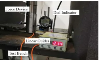
In order to obtain better experimental effect and take feasible experimental methods, the magnitude of electromagnetic force is measured with the indirect measurement method in the experiment, as shown in Figure 2. The dial indicator is used to measure the infinitesimal displacement of sliding block in the power-up state of linear motor; force is applied to the primary through the force application device to make the dial indicator reading consistent with the previous one, and the magnitude of the applied force is equivalent to the electromagnetic force. The electromagnetic force used in the simulation and calculation as below is measured by this method.
[image:3.595.212.384.633.737.2]Establishment of Finite Element Model of the Linear Motor Feed Drive System
Establishment of Simulation Model of the Linear Motor Feed Drive System
[image:4.595.193.404.244.319.2]The experimental object studied in this paper was a workbench of self-built linear motor feed drive system, on which three linear motors were equipped. All the important structural features were retained when the simulation model was established. The definition of material property and grid division were performed on the Ansys Workbench. The materials were then cut and separated according to the distributed structural features of joint surface between the sliding block and linear guide, and the grid density was increased to improve the computational accuracy. A model with the highest grid quality was obtained after several attempts of grid division. The final grid quantity was 167,831. The grid division result of finite element simulation model in the linear motor feed drive system is shown in Figure 3.
Figure 3. FEM of linear motor feed drive system.
Equivalent Processing of Joint Surface and Boundary Condition Setting
The equivalent dynamic model of slide guide joint surface can be represented by using the spring-damping element. The stiffness of bolted joint surface between the foundation and guide rail, sliding block and primary of linear motor is much larger than that between the sliding block and linear guide, with little effect on the dynamic characteristics of the system, so consolidation processing is adopted in the model. For the joint surface between the sliding block and linear guide that is mainly studied in this paper, the spring-damping element is used to conduct an equivalent processing of joint surface in the X and Y directions [17], as shown in Figure 4.
Figure 4. Vibration modal of joint.
Modal Test of Linear Motor Feed Drive System
The Identification Method of Dynamic Parameters of Slide Guide Joint Surface
The method to identify the dynamic characteristic parameters of joint surface of linear slide guide is adopted in this paper based on the response surface method. The basic steps are as follows. Firstly, the modal test is conducted on the slide guide joint surface, so as to get the natural frequency, modal shape and frequency-damping ratio of the slide guide joint surface in the first several orders. Secondly, a finite element model of the slide guide joint surface is established, the sample points of dynamic characteristic parameters are selected, and a simulation model is then constructed. Finally, the simulation result is compared with the analysis result of modal test, so as to optimize the identification method, achieve the purpose of error reduction, and improve the identification precision.
Modal Experiment Analysis System
[image:4.595.232.365.459.541.2]experimental system generally consists of excitation system, measurement system and analysis system. After the input excitation of the structure, the output response data and excitation data are recorded with a sensor and transmitted to the computer for processing. The modal parameter of vibration system can be identified after a series of calculations.
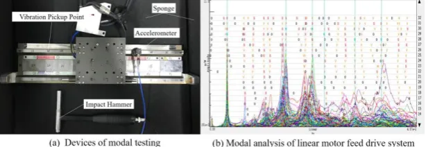
[image:5.595.165.431.202.260.2]The analysis method of modal test used in this paper belongs to the category of frequency domain [18], and the experimental system is shown in Figure 5. The 3-axis accelerometer is used to collect the acceleration signal of experimental subject through the shock excitation of force hammer, and the linear motor feed drive system is modally tested by the LMS Test.Lab modal test and analysis software, so as to obtain the test-piece modality.
Figure 5. Schematic diagram of modal testing.
Modal Parameter Identification
The vibration mode chart obtained from the modal experiment is expressed by the vibration mode of measuring points. Both excessively small and large number of measuring points may affect the efficiency and accuracy of experiment. Therefore, it is necessary to design the position and distribution density of measuring points to obtain better experimental effect. After multiple test analysis, the point distribution in this paper is shown in Figure 6(a), with a total of 36 measuring points. Measurement is conducted by fixing the tapping points and moving the acceleration sensor in the test. Pulsed excitation is performed by tapping on the fixed test-piece points with a force hammer. Every measuring point is knocked three times, so as to observe the correlation of the three times of tapping. The tapping of this measuring point can be confirmed if the correlation meets the requirement; the measuring point needs to be tapped again to ensure the quality of tapping if the correlation fails to meet the standard. At the same time, it should be noted that the coordinate direction of sensor should be consistent with the setting direction in the tapping test, and the tapping force should be controlled improve the signal quality, so as to obtain high-quality experimental data.
Figure 6. Modal experiment analysis system.
The LMS Test.Lab software is used to analyze the data of measuring points, to get the experimental modal analysis chart of the linear motor feed drive system, as shown in Figure 6(b). In the chart, the horizontal axis represents the frequency, and the vertical axis represents the amplitude of real part of frequency response function. The inherent frequency and damping ratio of the linear motor feed drive system in various orders can be obtained by selecting the frequency values corresponding to stable curve peaks.
Harmonic Response Analysis
[image:5.595.144.453.490.596.2]conditions through analysis. It can help to find the continuous dynamic characteristics of the structure to be analyzed, seek out the weak link of the system, and reasonably choose the parameter structure in the subsequent optimization design process to avoid the parameters from falling in the resonance interval. In the process of harmonic response analysis, it is necessary to merely calculate the forced vibration in the steady state of structure, instead of considering the transient vibration of the structure when the shock excitation is started.
According to the classical kinetic equation, when the system is subject to harmonic excitation, the differential equation of motion is as shown in Equation (4-1):
[𝑀]{𝑥̈(𝑡)} + [𝐶]{𝑥̈(𝑡)} + [𝐾]{𝑥(𝑡)} = {𝐹 𝑐𝑜𝑠 𝜔(𝑡)} (4) Where, [𝑀] indicates the mass matrix of the system,[𝐶]indicates the damping matrix of the system, [𝐾] indicates the stiffness matrix of the system, {𝑥(𝑡)} indicates the displacement vector of the system, {𝐹 𝑐𝑜𝑠 𝜔(𝑡)} indicates the harmonic load received by the system, and 𝑡 indicates the time.
According to the above differential equation, the response of the system under different frequencies can be obtained by inputting continuous external loads of different frequencies, so as to further get the response of the system on the entire spectral bandwidth.
The harmonic response analysis of the linear motor feed drive system in the Y direction is conducted by using the harmonic response module in the Ansys Workbench. The frequency broadband range was selected as 300-3500 Hz based on the results of modal test.
The dynamic performance of the linear motor feed drive system in state 1 (power-off) and state 2 (power-on) is tested in this paper. The stiffness in state 1 and state 2 in the Y direction can be obtained by finite element simulation of harmonic response analysis, as shown in Table 1.
Table 1. Dynamic stiffness of Y direction. State 1 State 2 Increase Stiffness(N/mm) 104,547 148,551 42.1%
It can be seen that the dynamic stiffness in the power-on state increases by about 42.1% than that in the power-off state, which indicates that the electromagnetic force of the linear motor drive system has a positive effect on the stiffness of the linear motor feed drive system.
Dynamic Characteristic Parameter Identification of Linear Motor Feed System
[image:6.595.64.541.639.724.2]Masataka Yoshimura proposed that the dynamic characteristics of the unit-area joint surface can be applied to the general joint surface with same contact surface characteristic but different shapes and contact area, as long as the average contact pressure of the joint surface is the same. The advantage of this method is that the integral of joint surface area can be obtained by measuring the dynamic characteristic parameters of unit-area joint surface under a certain condition, in order to get the complete dynamic characteristic parameters. Therefore, when the dynamic characteristic parameter identification of joint surface of linear motor feed drive system is performed, the parameter values of the spring-damping element of nodes in the same direction can be set as the same value [19].
Figure 7. The first 6-order natural frequencies of power-on state.
Table 2. Linear motor feed drive system modal analysis result of power-off state. Order Experimental result(Hz) Simulation result(Hz) Relative error (%)
1 344.3 316.3 8.1
2 1416.1 1308.6 7.6
3 1879.9 1985.5 5.6
4 2017.1 2113.9 4.8
5 2519.6 2602.2 3.3
6 3096.6 3137.4 1.3
Table 3. Linear motor feed drive system modal analysis result of power-on state. Order Experimental result(Hz) Simulation result(Hz) Relative error (%)
1 344.3 319.6 7.2
2 1502.7 1466.7 2.4
3 2022.4 2118.0 8.2
4 2259.1 2171.5 3.9
5 2860.6 2975.0 4.0
6 3384.2 3412.8 0.9
Summary
1) To analyze the influence of electromagnetic attraction on the the joint surface between the sliding block and linear guide, The resultant electromagnetic force was conducted on the linear motor in the running state. An indirect measurement method is established to measure the magnitude of electromagnetic force of the linear motor. Then the finite element simulation model of the linear motor feed system was established.
2) The influence of electromagnetic force on the dynamic stiffness in the linear motor feed drive system is studied. It indicated that the electromagnetic force plays a key role in improving the stiffness of the linear motor feed drive system. In the case of the equipment used in this paper, the dynamic stiffness of the system in the power-on state increases by 42.1% than that in the power-off state.
3) Based on the modal experimental analysis and response surface method, a method for identifying the dynamic characteristic parameters of joint surface in the linear motor feed drive system was proposed. The error is kept less than 9% through the contrastive analysis of finite element simulation and modal test results, which verified the feasibility of the presented method.
Acknowledgement
We gratefully acknowledge the financial support for this research from the National Natural Science Foundation of China (Grant No. 51575301).
References
[1] Xia Jiakuan, Liu Xiaoxia, Wang Chengyuan. Direct Drive Linear Servo Motor for Machine Tool Feeding. Manufacturing Technology and Machine Tools, 2003, (4): 8-11.
[2] M. Burdekin, N. Baek, A. Cowley. Analysis of the local deformation in machine joints [J]. Mech.Eng.Sci.1979, 34(3):15~17. Reference to a chapter in an edited book:
[3] Yoshimura, Tao Zhifan translation. Computer-aided design of combined surface dynamics data to improve the structural rigidity of machine tools [J]. Machine tools, 1979 (1).
[4] Yu Dejie, Song Jianwei, Peng Zemin, Xu Yanshen. A Method for Identifying Dynamic Parameters of Mechanical Structure Joint Surface[J]. Chinese Journal of Applied Mechanics
[6] Chen Jiu, Huang Yumei. A Study on the Static Behaviors of Rolling Guideways[J]. Manufacturing Technology and Machine Tools, 2003(11): 32-34.
[7] Chlebus E. Dybala B. Modeling and calculation of properties of sliding guideway [J]. International Journal of Machine Tools and Manufacture. 1999. 39(12):1823-1839
[8] Wang Zhonghou, Yuan Keke, Li Gang. Optimization Identification for Dynamic Characteristics Parameters of sliding joints based on response surface methodology[J]. China Mechanical Engineering, 2016, 27(05): 622-626.
[9] LEE W J.KIM S I. Joint stiffness identification of an ultraprecision machine for machining large-surface micro-feature [J]. International Journal of precision Engineering and Manufacturing, 2009. 10(5):115-121.
[10] Sun Ming-nan, Mi Liang, Gan Jing, Yin Guo-fu. An Optimum Identification Method of Dynamic Characteristic Parameters of Guideway Joint on a NC Machine Tool[J]. Journal of Sichuan University (Engineering Science Edition), 2012, 44(03):217-223.
[11] Wang Lihua, Luo Jianping, Liu Yubin, Huang Yayu. Research on Dynamic Characteristics of Key Joint Surface of Milling Machine[J]. Journal of Vibration and Shock, 2008(08):125-129+183.
[12] Zhang Yu, Liao Boyu. An Effective Method for Identifying the Parameters of Machine Tool Joints[J]. Journal of Kunming University of Science and Technology, 1998(02): 38-43.
[13] Gu Si-min. Experimental study on dynamic characteristic parameters of machine tool fixed joint surface [D]. Nanjing University of Science and Technology, 2011.
[14] Tang Renyuan. Theory and Design of Modern Permanent Magnet Motors. Beijing: Mechanical Industry Press, 1997.
[15] Ye Yunyue. Principle and Application of Linear Motor [M]. Beijing: Mechanical Industry Press, 2000.
[16] J. Duncan, C. Eng. Linear induction motor equivalent circuit model[J]. IEE Proc. Vol. 130, Pt.B, No. 1, Jan. 1983.51-57.
[17] Wang Zelin. Identification and Research on Characteristic Parameter of Machine Sliding Joint [D]. Beijing University of Technology, 2011.
[18] Li Jingkui, Shi Hong, Guo Jianbiao. Characteristics Analysis of Joint Surface Parameters of Machine Tool Guides Based on Finite Element Method[J].Modern Manufacturing Engineering, 2007(05):92-94.