2018 3rd International Conference on Information Technology and Industrial Automation (ICITIA 2018) ISBN: 978-1-60595-607-7
Gyro Axis Motion Modeling and Simulation
with Multi-error
Yundong Han, Yunhai Zhong, Su Wang, Guohui Lan and Wei Li
ABSTRACT
It is important practical significance for the further research to establish the gyroscope motion model with much error conditions and its simulation platform for the type of electromagnet control gyrocompass as the main reference point to provide a true instrument. According to its working principle, the mathematical model of the direct heading and constant velocity motion of the gyrocompass is established by analyzing the influence of velocity error, latitude error and inertial error. Then the simulation model is established with SIMULINK, and the rationality and accuracy of model is also verified through the comparison of simulation data and the actual observation results.1
INTRODUCTION
The electronic gyrocompass is a kind of pointing instrument that make gyroscope automatically find north and stably direct north by electromagnetic control. And it is the abbreviation of electromagnetic control gyrocompass. Gyroscope is the core sensitive element of electromagnetic control gyrocompass. According to the characteristics of gyroscopic inertia and procession, gyrocompass achieves the function of finding north by applying different electromagnetic moments. This paper will establish the gyroscope motion model with multi-error and then build the simulation platform, fully considering of multi spindle motion error conditions, based on the basic law of the gyroscope movement.
1
ESTABLISHMENT OF A MATHEMATICAL MODEL FOR THE GYROSCOPE MOTION
Selection of Error Terms
The study object of this article is a type of electromagnet control gyrocompass made in China, using electromagnetic actuator torque of gyroscope, with the characteristics of small size, high precision, good reliability, and have two working mode, wide application range, currently has a wide application.
But in the work process, the gyroscope of this type of electronic compass will easily cause the latitude error, velocity error and inertial error in the process of exercise because of a variety of factors such as the inaccurate latitude setting, power frequency fluctuation, main bearing friction torque, gyroscope migration, the spindle being not level, and the friction of Y axis. In addition, other factors can also cause motion error on the gyroscope, such as latitude error, velocity error, inertial error in the process of exercise in addition, the motion error due to error, error, friction hinge swing error and gravity offset error, bracket error and parameter instability and so on.
Because of the latter 6 errors are all small quantities, not the main error sources, so the 6 minor errors are ignored during the design of the spindle motion mathematical model in this paper, and mainly consider three main error items: velocity error, latitude error and inertia error. Among them, the velocity error and latitude error are compensated in the mathematical model, and the inertial error is attenuated by the limit pendulum module in the simulation model.
Establishment of a Mathematical Model
Because of the diversity of the base movement, the motion law of the gyroscope will be studied using the constant speed motion of the base as a typical motion. When the gyrocompass goes directly along the earth with the same speed, the
gyroscope spindle will produce the relative angular speed tan e E
R V
and
e N
e E
R V
R V
, because of the motion of the ship relative to the geographic
coordinate system. At this time, the mathematical model of the spindle motion law is the formula (1).
Among them, is the forward angular velocity of the precession of the
the current geographical ship latitude, Re is the radius of the earth, H is rotor inertia of the gyro , Ky is the electromagnetic torque coefficient.
0 1 ) ( ) ( ) ( 1 2 1 H K R V R V t K H K R V tg R V z e N e E p y e E e E (1)
Because the latitude error and velocity error is caused by the gyrocompass itself, that two kinds of error need to be inside compensated for electronic compass. Based on manually or automatic inputting of V, and K, namely speed, heading and geographical latitude ship, the moment the amount of compensation is calculated to compensated latitude error and velocity error, which was applied to a torque device to offset the latitude error and the velocity error, making gyroscope back to the proper stable position.
The error compensation parameters of the setting of the compass are the binding speed V0 and the binding latitude 0, then after the compensation, the gyroscope
motion rule is the formula (2) .
0 1 ) ( ) ( sin ) ( 0 1 0 0 0 2 1 e N z e N e E p e E e y e E e E R V H K R V R V t K tg R V H K R V tg R V (2)
In the formula (2): VE0 V0sinK, VN0 V0cosK.
STABLISHMENT OF A GYROSCOPE MOTION SIMULATION PLATFORM
Input Module
The input module consists of a variable input module and a constant assignment module. The variable input module is the Subsystem (input) sub-module, which contains 8 input-data module from the workspace, including the local latitude, bound ship course and speed, the binding speed, working condition parameter and initial position parameters of the gyrocompass, and these arguments are translated to the function module.
Output Module
The output module include oscilloscope display module (Scope), the output data to the working space module (To Workspace) and output to the working space module (Out1), and the main function is to achieve the simulation results, as well as some variable value is transmitted to the MATLAB space, and then by calling these numerical stability of the theoretical value of spindle.
Comparative Analysis of Simulation Results with Test Equipment
Using measured data is the most reliable method to verify the accuracy of the simulation model. Therefore, the experiment of electronic gyrocompass under gyrocompass state with uniform straight course was performed, recording all data of spindle movement. At the same time, the related parameters of simulation model was set to the actual parameters of the experiment, and the experimental results are compared with the simulation results to verify the accuracy and rationality of the model.
Actual Test Results of Equipment
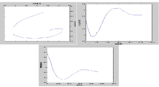
Restricted by laboratory environment, real experiments can only be performed under static base, and this state can be regarded as the special state that the uniform linear motion velocity is zero. Therefore, the parameters of the electric compass can be determined as that the true course is 125.5 degrees, the initial course of the compass is 126.2 degrees, the initial height angle is -16.5 angle, the binding latitude is 39 degrees, the binding speed is 0kn, the compass working state is compass state and the latitude is north latitude.
(a)Azimuth angle curve(b)Azimuth angle curve(c)Height angle cure
Figure 1. The motion rule of electronic controlled gyroscope based on truly measured data.
Data Result Analysis
Comparing the measured results and the simulation results found the two results. One was that the azimuth and elevation angle change curve with time change curve with time was consistent, and the amplitude and period of oscillation curve and curve were good agreement. Two was that the azimuth angle changed with height curve overall a similar trend, but there was little difference in the final stability point. The stable point by measured data was (r 0.4,r 0.09), and the stable
point by simulation data was (r 0.271,r 0.032), and all were different from the
theory value, etc. (r 0, r 0).
The main reason is the following three points. The one is that the stable point of theoretical analysis is difficult to implement in practice , and there always is a spindle position deviation. The two is that variation of azimuth and elevation angle decreases with the spindle gradually stabilized in the process of experiment, and only rely on manual data reading will have a certain error with the limited conditions. The three is that there is absolute error itself using the use of compass stable course as a true course.
CONCLUSIONS
(1) Based on the working principle of an electronic gyrocompass, the motion model of gyroscope is established, and the main three error is analyzed, which provides a theoretical basis for further research on its error elimination.
(3) Through the comparative analysis of the simulation results and the measured results, it verifies the rationality and accuracy of the spindle motion model and its simulation model, showing the usability of the simulation platform provided by this paper.
(4) Because this type of compass is a large number of main equipment that our navy ships are equipped with at present, and the gyroscope model and simulation platform established by it are directly aimed at this compass, so its theory and application value will be very significant.
REFERENCES
1. Yundong Han, Tianwei Li, Sihua He. Application of Fuzzy Fault Tree Analysis in Fault Diagnosis of Navigation Equipment [J]. Ship Science and Technology, 2005, (4): 68-70.
2. Qunzhe Yuan; Hongjin Zhou; Yongxin Jiang. Simulation of North-Seeking Process of Electrically Torqued Gyrocompass [J]. Navigation of China, 2017, 40(01): 4-7+31.
3. Puqiang Yan, Zhaoying Zhou. The Ballistic Errors of an Electrically Torqued Gyrocompass and its Compensation [J]. Journal of Tsinghua University, 1980, (01): 61-72.
4. Xiong Wei, Zhiyuan Cai, Yuxuan Qi, Dechun Li. High-Accuracy Inertial Navigation System with H-modulation Gyro Monitoring [J]. Journal of Chinese Inertial Technology, 2010, (4): 388-395.
5. Cheng Li, Baiyong An, Lijiang Yu. Study on the Data Fitting of Electromagnet Control Gyro Compass Course Value under the Status of Impact [J]. Ship Engineering (2): 99-101.