1008
SIMULATION FOR VEHICLE ACTIVE SUSPENSION
CONTROL BASED ON DIFFERENT FEEDBACK
PARAMETERS
1JINGYUE WANG, 2HAOTIAN WANG, 3LIXIN GUO
1
School of Automobile and Transportation, Shenyang Ligong University, Shenyang 110168, Shenyang, China
2 Shenyang Aerospace University, Shenyang 110136, Shenyang, China
3School of Mechanical engineering, Northeastern University, Shenyang 110819, Shenyang, China
ABSTRACT
A half-car model with four DOF was established to simulate the system. On the basis of this model, Self-adapt Parameters Fuzzy-PID control method of the active suspension system is described. In such a model, vehicle speed, vehicle body vertical acceleration, suspension dynamic deflection, the body vertical acceleration and suspension dynamic deflection integrated feedback were used respectively as the integrated feedback. The simulation results show that active suspension Self-adapt Parameters Fuzzy-PID control with the body vertical acceleration and suspension dynamic deflection as comprehensive feedback parameters compared with passive suspension can improve the ride comfort and driving stability in random excitation.
Keywords: Vehicle, Active Suspension, Fuzzy PID Control, Ride Comfort
1. INTRODUCTION
At present, vehicle suspension has obtained high performance damping effect by using optimal control method. Industrial countries have begun to study an active, semi-active suspension system based on vibration control in the 1970s. In the 1960s, foreign scholars have proposed the concept of active suspension. Industry developed in the 70's has been of active[1-2], semi-active[3-4] suspension system based on the active vibration control. Domestic and foreign scholars have applied optimal control[5-8], adaptive control[9-10], fuzzy control[11-12], artificial neural network[13-15] to vibration control of vehicle suspension system. Modern control theory has made vibration control technology of the suspension system more perfect.
In the paper, the 1/2 body with four degrees of freedom suspension model is established as the research foundation, because that the automobile active suspension system is time-varying and nonlinear characteristic. Based on classical PID control, the self-adapt parameters fuzzy-PID controller of active suspension is designed combined with fuzzy control theory. In the process of designing the control system, the feedback of control system makes use of the vehicle body acceleration and the suspension dynamic deflection as the integrated feedback input. The simulation
results show that this control method is better than the passive suspension.
2. MODEL OF SYSTEM
A simplified 1/2 model with four degrees of freedom is established to simulate the system as shown in figure 1.m1f and m1r are the front and
back wheels quality; m2f and m2rare the front and
rear axle assignment quality; m2is the vehicle body centroid allocated quality; z1f and z2f are the
front and rear wheel displacement; z1r and z2r are
the front and rear upper body displacement; zcis the centroid displacement; zqf and zqr are the front and rear surface roughness displacement input;θ is the pitch angle; k1f and k1rare the front
and rear elastic stiffness; k2f and k2rare the front,
rear suspension spring stiffness; c2f and c2rare the
front and rear suspension damping coefficient;
L
is the wheelbase; a is the distance of front axle to centroid; b is the distance of rear axle to centroid;f
1009
Figure 1: Model Of 1/2 Body With Four DOF
The dynamics equation of system are
= − − + − + − − = − − + − + − − = + − + − + + − + − + = + − + − − + − + − + 0 ) ( ) ( ) ( 0 ) ( ) ( ) ( 0 ) ( ) ( ) ( ) ( 0 ] ) ( ) ( [ ] ) ( ) ( [ 2 1 2 2 1 2 1 1 2 1 2 1 2 2 1 2 1 1 2 1 1 2 2 1 2 2 1 2 2 1 2 2 2 1 2 2 1 2 2 1 2 2 1 2 2 r r r r r r f qr r f f r f f f f f f f qf f f f f r r r r r r r f f f f f f f c f f f f f f f r r r r r r r u z z k z z c z z k z m u z z k z z c z z k z m u z z c z z k u z z c z z k z m u z z c z z k a u z z c z z k b J θ (1)
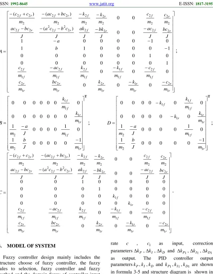
The equation of state and input equation are established as follows
+ = + = DU CX Y BU AX X
(2)
In which
[
]
Tr f r f r r f f
c z z z z z z z z
z
X = θ 2 − 1 2 − 1 1 1 1 1
,
[
]
Tr f qr
qf z u u
z
U =
,
[
]
Tr f qr r r qf f f r r f f
c z z z z k z z k z z z z
z
1010 − − − − − − − − − − − − − − − + − + − = r r r r r r r r r r f f f f f f f f f f r f r f r f r f r f r f r f r f m c m k m k m bc m c m c m k m k m ac m c b a J bc J ac J bk J ak J c b c a J bc ac m c m c m k m k m bc ac m c c A 1 2 1 1 1 2 1 2 1 2 1 2 1 1 1 2 1 2 1 2 2 2 2 2 2 2 2 2 2 2 2 2 2 2 2 2 2 2 2 2 2 2 2 2 0 0 0 0 0 0 1 0 0 0 0 0 0 0 0 1 0 0 0 0 0 0 1 0 0 0 0 1 1 0 1 0 0 0 0 1 0 0 ) ( 0 0 ) ( ) (
;
T − − = r f r r f f m J b m m J a m m k m k B 1 2 1 2 1 1 1 1 1 0 0 0 0 0 1 0 1 0 0 0 0 1 0 0 0 0 0 0 0 0 0 0 0 0 0 0;
T − − − − = r f r r r f f f m J b m m J a m m k k m k k D 1 2 1 2 1 1 1 1 1 1 1 0 0 0 0 0 1 0 1 0 0 0 0 1 0 0 0 0 0 0 0 0 0 0 0 0;
− − − − − − − − − − − − + − + − = r r r r r r r r r r f f f f f f f f f f r f r f r f r f r f r f r f r f r f m c m k m k m bc m c m c m k m k m ac m c k k J bc J ac J bk J ak J c b c a J bc ac m c m c m k m k m bc ac m c c C 1 2 1 1 1 2 1 2 1 2 1 2 1 1 1 2 1 2 1 2 1 1 2 2 2 2 2 2 2 2 2 2 2 2 2 2 2 2 2 2 2 2 2 2 2 2 0 0 0 0 0 0 0 0 0 0 0 0 0 0 0 0 0 0 0 0 0 0 0 0 1 0 0 0 0 0 0 0 0 1 0 0 0 0 ) ( 0 0 ) ( ) (.
3. MODEL OF SYSTEM
Fuzzy controller design mainly includes the structure choose of fuzzy controller, the fuzzy rules to selection, fuzzy controller and fuzzy method and the domain fuzzy of controller input and output variables.
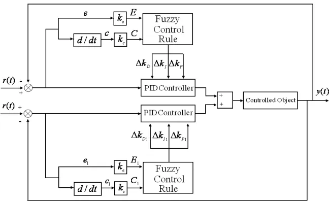
3.1Structure of Self-adapt Parameters Fuzzy-PID Controller
The paper selects the vehicle body vertical acceleration and the suspension dynamic deflection as the integrated feedback input. Fuzzy controller takes their deviatione,e1 and its change
rate c , c1 as input, correction
parameters∆kP ,∆kI ,∆kD and ∆kP1,∆kI1,∆kD1
as output. The PID controller output
[image:3.612.94.522.74.625.2]parameterskP,kI,kD and kP1,kI1,kD1 are shown in formula 3-5 and structure diagram is shown in figure 2.
P
k =kP′+∆kP, kP1=kP′1+∆kP1 (3)
kI=kI′+∆kI, kI1=kI′1+∆kI1 (4)
1011
3.2Fuzzy Subset of Input and Output Variables
For input and output variables, fuzzy state is used by seven fuzzy sets, both for the {NB, NM,
NS, ZE, PS, PM, PB}.The fuzzy domain
e
and1
e
are (-0.5,0.5). The fuzzy domain of errorchange rate
c
andc
1 are (-0.5, 0.5). The fuzzy domain∆kP ,∆kP1,∆kI1 and ∆kI,∆kD,∆kD1 are in (-0.5, 0.5). Fuzzy subsets of input variable and output variable use triangular membership functions.3.3Fuzzy control rule
The fuzzy control rules are an important component of fuzzy controller. It is described by means of the input and output of a controller relationship between them, namely, the fuzzy relationship between them. The fuzzy control rule is based on people's thinking, with the method of fuzzy reasoning is given. In the paper, the fuzzy controller with 2 inputs is described by 2 language fuzzy sets, forming 49 control rules. The fuzzy control rule table of three parameters are shown in figure 4.1-4.3(∆kP1,∆kI1and∆kD1 are samed as
P
k
∆ ,∆kI and ∆kD).
[image:4.612.150.474.272.471.2]Figure 2: Self-Adapt Parameters Fuzzy-PID Control Principle Diagram
Table 1: Fuzzy Control Rule Table Of ∆kp
p
k
∆ C
NB NM NS ZO PS PM PB
E
NB PB PB PM PM PS ZO ZO
NM PB PB PM PS PS ZO NS
NS PM PM PM PS ZO NS NS
ZO PM PM PS ZO NS NM NM
PS PS PS ZO NS NS NM NM
PM PS ZO NS NM NM NM NB
1012
Table 2: Fuzzy Control Rule Table Of ∆kI
l
k
∆ C
NB NM NS ZO PS PM PB
E
NB NB NB NM NM NS ZO ZO
NM NB NB NM NS NS ZO ZO
NS NB NM NS NS ZO PS PS
ZO NM NM NS ZO PS PM PM
PS NM NS ZO PS PS PM PB
PM ZO ZO PS PS PM PB PB
PB ZO ZO PS PM PM PB PB
Table 3: Fuzzy Control Rule Table Of ∆kD
D
k
∆ C
NB NM NS ZO PS PM PB
E
NB PS NS NB NB NB NM PS
NM PS NS NB NM NM NS ZO
NS ZO NS NM NM NS NS ZO
ZO ZO NS NS NS NS NS ZO
PS ZO ZO ZO ZO ZO ZO ZO
PM PB NS PS PS PS PS PB
PB PB PM PM PM PS PS PB
4. MODEL OF SYSTEM
[image:5.612.87.296.429.583.2]The suspension parameters of SANTANA 2000 car are shown in table 4.
Table 4: Parameters Of SANTANA 2000 Name Valve Company
m1f 98 kg
m1r 98 kg
m 975.37 kg
J 1647 kg·m2
k1f 604.69 kN/m
k1r 985.97 kN/m
k2f 45.48 kN/m
k2r 52.29 kN/m
c2f 2546.5 N·s/m
c2r 2840.6 N·s/m
a 1.1135 m
b 1.5415 m
When the vehicle travels on grade B Road and
v=50m/s, road roughness coefficient
1 2 6
0) 64 10 /
(n = × − m m−
Sq , n0 =0.1 m−1 , Velocity
spectrum density is a white noise ,
( )
f S f n S n v fSq( )= 2π 2 q( )=4π2 02 q( 0) , The white noise input is regarded as random road displacement excitation. Simulation study on Self-adapt Parameters Fuzzy-PID control of active suspension with acceleration feedback(ACC),
speed feedback(Speed),suspension dynamic
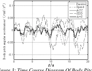
deflection feedback(SDD) and acceleration and suspension dynamic deflection comprehensive feedback(A+S). Body pitch angle acceleration response, the body acceleration, wheel dynamic load response, front suspension dynamic deflection response, rear wheel dynamic load response and rear suspension dynamic deflection are simulation. Simulation comparison results of response are shown in figures 3-8.
[image:5.612.346.505.473.595.2]Figure 3: Time Course Diagram Of Body Pitch
1013 Figure 4: Time Course Diagram Of Body
Acceleration
Figure 5: Time Course Diagram Of Front Wheel Dynamic Load
Figure 6: Time Course Diagram Of Front Suspension
Dynamic Deflection
[image:6.612.319.522.254.430.2]Figure 7: Time Course Diagram Of Rear Wheel
Dynamic Load
Figure 8: Time Course Diagram Of Rear Suspension
Dynamic Deflection
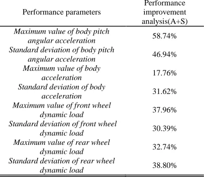
Table 5: Performance Improvement Analysis
Performance parameters
Performance improvement analysis(A+S)
Maximum value of body pitch
angular acceleration 58.74%
Standard deviation of body pitch
angular acceleration 46.94%
Maximum value of body
acceleration 17.76%
Standard deviation of body
acceleration 31.62%
Maximum value of front wheel
dynamic load 37.96%
Standard deviation of front wheel
dynamic load 30.39%
Maximum value of rear wheel
dynamic load 32.74%
Standard deviation of rear wheel
dynamic load 38.80%
As can be seen from table 5, compared with
passive suspension, body pitch angular
acceleration, body acceleration, front wheel dynamic load, front wheel dynamic load and rear wheel dynamic load of Self-adapt Parameters Fuzzy-PID active suspension, are significantly reduced. The car's ride and handling stability is greatly improved. The defect is that front and rear suspension dynamic deflection has certain increases compared with passive suspension. The maximum are 0.053m and 0.049m. The limit of the car suspension travel is 0.07-0.09m. As long as the suspension dynamic deflection is in the limit travel of the suspension, the suspension dynamic deflection increases in exchange for other vehicle performance improved, such as ride comfort.
5. CONCLUSION
[image:6.612.118.281.531.670.2]1014 effective, and the effect of the comprehensive control is good. Compared with the passive suspension, the design of active suspension self-adaptive fuzzy PID control can reduce the body pitch angular acceleration, body vertical acceleration, wheel dynamic load. The vehicle ride comfort and handling stability have been improved obviously, which has achieved the anticipated goal and effect.
ACKNOWLEDGEMENTS
This work was supported by Program for New Century Excellent Talents in University (NCET-08-0103), the Research Fund for the Doctoral Program of Higher Education (20100042110013), the Fundamental Research Funds for the Central Universities of China (N110403008), Natural Science Foundation of Liaoning Province of China (201102071), Shenyang City Science Projects (F11-264-1-46) and the Science and Technology Research Projects of Education Department of Liaoning Province of China (L2012068).
REFERENCES:
[1] G. Priyandoko, M. Mailah, H. Jamaluddin, “Vehicle active suspension system using skyhook adaptive neuro active force control”,
Mechanical Systems and Signal Processing, Vol. 23, No. 3, 2009, pp. 855-868.
[2] H. J. Gao, J. Lam,C. H. Wang, “Multi-objective control of vehicle active suspension systems via load-dependent controllers”, Journal of Sound and Vibration, Vol. 290, No. 3-5, 2006, pp. 654-675.
[2] H. P. Du, K. Y. Sze, J. Lam, “Semi-active H∞
control of vehicle suspension with magneto-rheological dampers”, Journal of Sound and Vibration, Vol. 283, No. 3-5, 2005, pp. 981-996.
[4] M. Zapateiro, N. Luo, H. R. Karimi, et al., “Vibration control of a class of semiactive suspension system using neural network and backstepping techniques”, Mechanical Systems and Signal Processing, Vol. 23, No. 6, 2009, pp. 1946-1953.
[5] J. Marzbanrad, G. Ahmadi, H. Zohoor, et al., “Stochastic optimal preview control of a
vehicle suspension”, Journal of Sound and Vibration, Vol. 275, No. 3-5, 2004, pp. 973-990.
[6] M. Yamashita, K. Fujimori, K. Hayakawa, “Application of H-infinity control to active suspension systems”, Automatica, Vol. 30, No. 11, 1994, pp. 1717-1729.
[7] S. B. Choi, S. S. Han, “H-infinity control of electrorheological suspension system subjected parameter to uncertainties”, Mechatronics, Vol. 14, No. 13, 2003, pp. 639-657.
[8] H. P. Du, K. Y. Sze, J. Lam, “Semi-active H∞
control of vehicle suspension with magneto-rheological dampers”, Journal of Sound and Vibration, Vol. 283, No. 3-5, 2005, pp. 981-996.
[9] A. Alleyne, J. K. Hedrick, “Nonlinear adaptive control of active suspensions”, IEEE Transactions on Control Systems Technology, Vol. 3, No. 1, 1995, pp. 94-101.
[10] S. J. Huang, H. Y. Chen, “Adaptive sliding controller with self-tuning fuzzy compensation for vehicle suspension control”, Journal of Sound and Vibration, Vol. 16, No. 10, 2006, pp. 607-622.
[11] T. Yoshimura, “Active suspension of vehicle systems using fuzzy logic”, International Journal of Systems Science, Vol. 27, No. 2, 1996, pp. 215-219.
[12] E. C. Yeh, Y. J. Tsao, “A fuzzy preview control scheme of active suspension for rough road”, IEEE International Journal of Vehicle Design, Vol. 15, No. 1-2, 1994, pp.166-180.
[13] S. Yildirim, “Vibration control of suspension systems using a proposed neural network”, Journal of Sound and Vibration, Vol. 277, No. 4-5, 2004, pp. 1059-1069.
[14] G. Priyandoko, M. Mailah, “Vehicle active suspension system using skyhook adaptive neural active force control”, Mechanical Systems and Signal Processing, Vol. 23, No. 3, 2009, pp. 855-868.
[15] I. Eski, S. Yildirim, “Vibration control of vehicle active suspension system using a new robust neural network control system”,
Simulation Modelling Practice and Theory, Vol. 17, No. 5, 2009, pp. 778-793.
![Assessment of Physiological Health Status in Relations to Different Anthropometric and Cardio respiratory Measures of Head Supported Load Carrying Male Porters of Sikkim, India [Article Retracted]](data:image/gif;base64,R0lGODlhAQABAIAAAP///wAAACH5BAEAAAAALAAAAAABAAEAAAICRAEAOw==)