RESEARCH, INC.
CRAY-1® AND CRAY X-MP
COMPUTER SYSTEMS
CRAY-OS VERSION 1
REFERENCE MANUAL
c:
RESEARCH, INC.
CRAY-1® AND CRAY X-MP
COMPUTER SYSTEMS
CRAY-OS VERSION 1
REFERENCE MANUAL
SR-0011
C:li=liJ~A.~:-r'
RECORD OF REVISION RESEARCH. INC. PUBLICATION NUMBER SR-OOll
Each time this manual is revised and reprinted, all chan~es issued against the previous version in the form of change packets are incorporated into the new version and the new version IS assigned an alphabetic level. Between reprints, changes may be issued against the current version in the form of change packets. Each change packet is assigned a numeric designator starting with
01 for the first change packet of each revision level. '
Every page changed by a reprint or by a change packet has the revision level and change packet number in the lower righthand corner. Changes to part of a page are noted by a change bar along the margin of the page. A change bar in the margin opposite the page number indicates that the entire page is new; a dot in the same place indicates that information has been moved from one page to another, but has not otherwise changed.
Requests for copies of Cray Research, I nco publications and comments about these publications should be directed to:
CRAY RESEARCH, INC., 1440 Northland Drive,
Mendota Heights, Minnesota 55120
Revision
A
B
C
C-Ol
o
0-01
Description
June 1976 - First printing
September 1976 - General technical changes; changes to JOB, MODE, RFL, and DMP statements; names of DS and RETURN changed to ASSIGN and RELEASE. STAGEI deleted, STAGEO replaced by DISPOSE. RECALL macro added and expansions provided for all logical I/O macros. RELEASE, DUMPDS, and LOADPDS renamed to DELETE, PDSDUMP, and PDSLOAD. Detailed description of BUILD added (formerly LIB). EDIT renamed to UPDATE.
February 1977 - Addition of Overlay Loader; deletion of Loader Tables (information now documented in CRI publication
SR-0012); deletion of UPDATE (information now documented in CRI publication SR-0013); changes to reflect current
implementation.
July 1977 - Addition of BKSPF, GETPOS, and POSITION logical I/O macros and $BKSPF, $GPOS, and $SPOS routines. Addition of
random I/O. Changes to dataset structure, JOB, ASSIGN, MODE, and DUMP statements; BUILD; logical I/O and system action macro expansions. General technical changes to reflect current implementation.
January 1978 - Correction to DISPOSE and LOR control statement documentation, addition of description of $WWDS write routine, miscellaneous changes to bring documentation into agreement with January 1978 released version of the operating system.
February 1978 - Reprint with revision. This printing is exactly the same as revision C with the C-Ol change packet added.
April 1978 - Change packet includes the addition of the ADJUST control statement; MODE and SWITCH macros; and PDD, ACCESS,
SAVE DELETE, and ADJUST permanent dataset macros.
Revision
E
E-Ol
F
F-Ol
F-02
G
G-Ol
SR-OOll
Description
July 1978 - Represents a complete rewrite of this manual. Changes are not marked by change bars. New features for
version 1.02 of the operating system that are documented in this revision include: addition of the MODIFY control
statement and the DSP, SYSIO, and DISPOSE macros; the addition of parameters to some control statements, the implementation of BUILD. The POSITION macro has been renamed SETPOS. Other changes to bring documentation into agreement with released version 1.02 of the operating system.
October 1978 - Change packet includes the implementation of ACQUIRE and COMPARE control statements; changes to the AUDIT and LOR control statements; changes to the MODE control statement and macro; the addition of control statement
continuation, GETPARAM, and the GETMODE macro; and other minor changes to bring documentation into agreement with the
released version 1.03 of the operating system.
December 1978 - Revision F is the same as revision E with change packet E-Ol added. No additional changes have been made.
January 1979 - Change packet includes implementation of some features of BUILD; the addition of the BUFIN, BUFINP, BUFOUT, BUFOUTP, BUFEOF, and BUFEOD macros and other minor changes to bring documentation into agreement with the released version 1.04 of the operating system.
April 1979 - Change packet includes the implementation of the DEBUG, RERUN, and NO RERUN control statements, the RERUN, NORERUN, and BUFCHECK macros; changes to DUMP, OSDUMP, AUDIT, and ASSIGN control statements; implementation of job rerun and memory resident datasets. Other minor changes were made to
bring documentation into agreement with the released version 1.05 of the operating system.
July 1979 - Reprint with revision. This printing obsoletes all previous versions. Changes are marked with change bars. The changes bring this documentation into agreement with the released version 1.06 of the operating system.
December 1979 - Change packet includes the implementation of the WAIT and NOWAIT options on the DISPOSE control statement;
the addition of a new DUMP format and eFT Linkage Macros; and other minor changes to bring documentation into agreement with
the released version 1.07 of the operating system.
Revision Description
H January 1980 - Revision H is the same as rev~s~on G with change packet G-Ol added. No additional changes have been made.
I April 1980 - Revision I is a complete reprint of this manual.
1-01
All changes are marked by change bars. New features for version 1.08 of the operating system that are documented in this revision include: the addition of the CALL and RETURN control statements, job classes, the NA parameter on permanent dataset management control statements, the NRLS parameter on the DISPOSE control statement and PDD macro, and the OW parameter on the COMPARE control statement. Changes to the LDR control statement include the addition of the LLD, NA, USA, and I parameters and the new selective load directives. New documentation has been added for unblocked I/O, including descriptions of the READU and WRITEU macros. Other new macros
include SETRPV, ENDRPV, DUMPJOB and the debugging aids SNAP, DUMP, INPUT, OUTPUT, FREAD, FWRITE, UFREAD, UFWRITE, SAVEREGS, and LOADREGS. Documentation on CRAY-l interactive
capabilities and changes to reflect the CRAY-l S Series have also been added. Other changes were made to bring
documentation into agreement with released Version 1.08 of the operating system.
with this rev~s~on, the publication number has been changed from 2240011 to SR-OOll.
Revision
1-02
J
J-Ol
K
SR-OOll
Description
July 1981 - This change packet includes changes to Job Control Language syntax; the addition of JCL block control statements for procedure definition (PROC, ENDPROC, &DATA, and prototype statement), conditional processing (IF, ELSE, ELSEIF, and ENDIF), and iterative processing (LOOP, EXITLOOP, and
ENDLOOP); the addition of ROLLJOB, SET, LIBRARY, ECHO, PRINT, FLODUMP, and SYSREF control statements; the addition of CSECHO macro; the addition of CNS parameter to CALL statement,
REPLACE parameter to BUILD statement, ARGSIZE parameter to ENTER macro, KEEP parameter to EXIT macro, USE parameter to ARGADD macro; the addition of the two JCL tables JBI and JST. Other minor changes were made to bring the documentation into agreement with the released version of 1.10 of the operating system.
February 1982 - Reprint. This reprint incorporates revision I with change packets 1-01 and 1-02. No other changes have been made.
June 1982 - This change packet includes the following
additions: magnetic tape characteristics, temporary and local dataset clarification, mass storage permanent datasets,
magnetic tape permanent datasets, tape I/O formats, interchange format, transparent format, new accounting information, *gn=nr parameter, several CHARGES parameters, the OPTION control statement, procedure definition, HOLD parameter, new information to the ACCESS control statement,
new tape dataset parameters, tape dataset conversion
parameters, SUBMIT job control statement, PDSDUMP and PDSLOAD sample listings, SID parameter on the LDR control statement, new loader errors, relocatable overlays, CONTRPV macro, SUBMIT macro, unrecovered data error information, POSITION macro, new PDD macro parameters, the LDT macro, and new glossary terms. The information formerly in Appendix C is now in the COS EXEC/STP/CSP Internal Reference Manual, publication SM-0040. Other miscellaneous technical and editorial changes were made to bring the documentation into agreement with version 1.11 of the operating system.
July 1982 - Reprint. This reprint incorporates revision J with change packet J-Ol. No other changes have been made.
Revision
L
Description
July 1983 - Revision L is a rewrite of this manual. Extensive editorial changes have been made, including moving macro
information which was in part 3 to publication SR-OOI2, Macro and Opdefs Reference Manual. Other major reorganization has occurred. Part 3 now contains job control language
structures. Information has been added on interactive job processing and job step abort processing. Major new features documented include enhanced support of tape datasets, the
FETCH control statement, memory management, enhancements to COS security, permanent dataset privacy, and support of the CRAY X-MP Computer System. Miscellaneous editorial and technical changes have been made to bring the documentation
PREFACE
This manual describes the external features of the Cray Operating System (COS). It is intended as a reference document for all users of COS. This manual is divided into three parts to separate the types of material presented.
PART 1 INTRODUCTION TO JOB PROCESSING
Part 1 describes the fundamentals of creating and running jobs on a Cray Computer System. This part describes the system components, storage of information on a Cray Computer, and job processing. Part 1 also introduces COS job control and describes the use of libraries.
PART 2 JOB CONTROL STATEMENTS
Part 2 describes each COS job control statement and gives the format of each with an explanation of its function.
PART 3 CONTROL STATEMENT STRUCTURES
Part 3 describes the control statement block structures
available with COS. Examples are provided at the end of part 3, section 4.
Other CRI publications that may be of interest to the reader are:
• CRAY-l Hardware Reference Manual, publication HR-0004
• CRAY-I S Series Mainframe Reference Manual, publication HR-0029 • CRAY-l M Series Mainframe Reference Manual, publication HR-0064 • CRAY X-MP Series Mainframe Reference Manual, publication HR-0032 • CRAY I/O Subsystem Reference Manual, publication HR-0030
• Mass Storage Subsystem Hardware Reference Manual, publication HR-0630
• Macros and Opdefs Reference Manual, publication SR-OOI2 • FORTRAN (eFT) Reference Manual, publication SR-0009
• CAL Assembler Version 1 Reference Manual, publication SR-OOOO • Library Reference Manual, publication SR-OOl4
• UPDATE Reference Manual, publication SR-OOI3
CONTENTS
PREFACE.
PART 1 INTRODUCTION TO JOB PROCESSING
1.
2.
INTRODUCTION •
HARDWARE REQUIREMENTS SYSTEM INITIALIZATION
CENTRAL MEMORY ASSIGNMENT AND CHARACTERISTICS Memory-resident COS •
User area of memory • Job Table Area JTA User field
MASS STORAGE CHARACTERISTICS • MAGNETIC TAPE CHARACTERISTICS
DATASETS •
DATASET MEDIUM •
Mass Storage datasets • Memory-resident datasets
Interactive datasets Magnetic tape datasets DATASET STRUCTURE
Blocked format
Blank compression Block control word • Record control word Interactive format
Unblocked format Tape formats
Interchange format • Transparent format • DATASET LONGEVITY
Temporary datasets Permanent datasets
Magnetic tape permanent datasets • Mass storage permanent datasets LOCAL DATASETS
SR-OOll ix
3.
4.
5.
DATASETS (continued)
DATASET DISPOSITION CODES
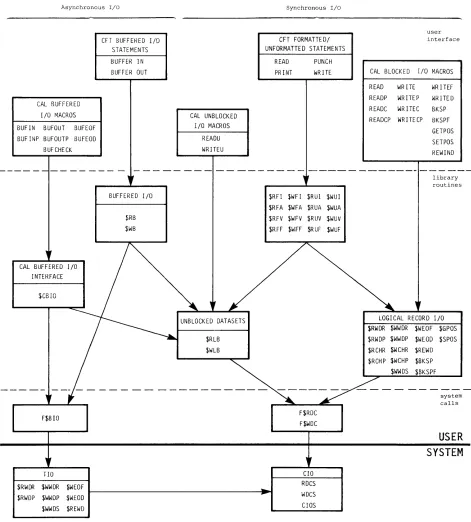
USER DATASET NAMING CONVENTIONS USER I/O INTERFACES
COS JOB PROCESSING •
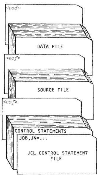
JOB DECK STRUCTURE •
GENERAL DESCRIPTION OF JOB FLOW Job entry •
Job initiation Job advancement • Job termination • JOB MEMORY MANAGEMENT
Initial memory allocation •
Modes of field length reduction • User management of memory
Management by control statement from the run stream Management from within a program •
Management associated with a program • System management of memory •
JOB RERUN
EXIT PROCESSING REPRIEVE PROCESSING
INTERACTIVE JOB PROCESSING •
JOB LOGFILE AND ACCOUNTING INFORMATION •
JOB CONTROL LANGUAGE •
SYNTAX VIOLATIONS VERBS
System verbs
Local dataset name verbs Library-defined verbs • System dataset name verbs • SEPARATORS •
PARAMETERS
positional parameters • Keyword parameters
Parameter interpretation Conventions •
LIBRARIES
PROCEDURE LIBRARY PROGRAM LIBRARY
OBJECT CODE LIBRARIES
FIGURES 1-1 1-2 2-1 2-2 2-3 2-4 2-5 2-6 3-1 3-2 3-3
Cray Computer System configuration •
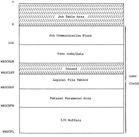
Central Memory assignment • • • • •
Data hierarchy within a dataset Format of a block control word •
Format of a record control word • • • •
Example of dataset control words (octal values shown) Interchange-format tape dataset (octal values shown) Relationship of levels of user I/O •
Basic job deck • • • • • • • • • • • •
User area of memory for a job e • • • • • •
Example of a job logfile • • •
TABLES
1-1 1-2 4-1
Physical characteristics of disk storage units • • • • • • Physical characteristics of 200 ips, 9-track tape devices Control statement separators • • • • • • • • • • • • • • •
PART 2 JOB CONTROL STATEMENTS
1. INTRODUCTION •
JOB DEFINITION
DATASET DEFINITION AND CONTROL • PERMANENT DATASET MANAGEMENT •
Mass storage dataset attributes. Permission control words • Public access mode attribute •
Public access tracking attribute • • Permits attribute
Text attribute • •
Notes attribute • • • • • • • • •
Establishing attributes for mass storage datasets • Existing permanent dataset •
New permanent dataset • • • • • • • • • •
The attributes dataset • • • • • • • • • • • Protecting and accessing mass storage datasets
Privacy • • • • • •
Access mode • • • • •
Dataset use tracking • Attribute association
DATASET STAGING CONTROL • • • •
PERMANENT DATASET UTILITIES • • • •
LOCAL DATASET UTILITIES ANALYTICAL AIDS
SR-OOll xi
2.
3.
4.
5.
INTRODUCTION (continued)
EXECUTABLE PROGRAM CREATION OBJECT LIBRARY MANAGEMENT
JOB DEFINITION AND CONTROL
JOB - JOB IDENTIFICATION • • MODE - SET OPERATING MODE
EXIT - EXIT PROCESSING • • • • • • • • • • • • • MEMORY - REQUEST MEMORY CHANGE • • • • • • • • • • SWITCH - SET OR CLEAR SENSE SWITCH • • • • •
* -
COMMENT STATEMENT • • • • • • • • • • • NORERUN - CONTROL DETECTION OF NONRERUNNABLE FUNCTIONS RERUN - UNCONDITIONALLY SET JOB RERUNNABILITY • • • • IOAREA - CONTROL USER'S ACCESS TO I/O AREA • • • • • • • CALL - READ CONTROL STATEMENTS FROM ALTERNATE DATASET RETURN - RETURN CONTROL TO CALLER • • • • • • • • ACCOUNT - VALIDATE USER NUMBER AND ACCOUNT •CHARGES - JOB STEP ACCOUNTING ROLLJOB - ROLL A USER JOB TO DISK SET - CHANGE SYMBOL VALUE • • • •
ECHO - ENABLE OR SUPPRESS LOGFILE MESSAGES • LIBRARY - LIST AND/OR CHANGE LIBRARY SEARCHLIST OPTION - SET USER-DEFINED OPTIONS • • • • • • •
DATASET DEFINITION AND CONTROL • • • • •
ASSIGN - ASSIGN DATASET CHARACTERISTICS RELEASE - RELEASE DATASET
PERMANENT DATASET MANAGEMENT • •
SAVE - SAVE PERMANENT DATASET ACCESS - ACCESS PERMANENT DATASET ADJUST - ADJUST PERMANENT DATASET MODIFY - MODIFY PERMANENT DATASET
DELETE - DELETE PERMANENT DATASET • • • • • PERMIT - EXPLICITLY CONTROL ACCESS TO DATASET
EXAMPLES OF PERMANENT DATASET CONTROL STATEMENTS • •
DATASET STAGING CONTROL
ACQUIRE - ACQUIRE PERMANENT DATASET DISPOSE - DISPOSE DATASET
SUBMIT - SUBMIT DATASET FETCH - FETCH LOCAL DATASET
6.
7.
8.
9.
PERMANENT DATASET UTILITIES
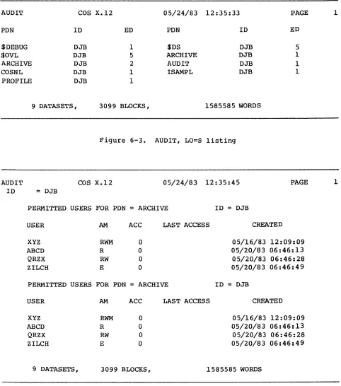
PDSDUMP - DUMP PERMANENT DATASET • PDSLOAD - LOAD PE~~ENT DATASET • AUDIT - AUDIT PERMANENT DATASET
LOCAL DATASET UTILITIES
COPYR - COpy RECORDS • COPYF - COpy FILES • • COPYD - COpy DATASET • SKIPR - SKIP RECORDS • SKIPF - SKIP FILES • • • SKIPD - SKIP DATASET •
. .
REWIND - REWIND DATASET • • • • • • • • WRITEDS - WRITE RANDOM OR SEQUENTIAL DATASET •
ANALYTICAL AIDS
DUMPJOB - CREATE $DUMP • •
DUMP - DUMP REGISTERS AND MEMORY • DEBUG - PRODUCE SYMBOLIC DUMP DSDUMP - DUMP DATASET
COMPARE - COMPARE DATASETS • • • •
PRINT - WRITE VALUE OF EXPRESSION TO LOGFILE • • FLODUMP - FLOW TRACE RECOVERY DUMP • • • • • • SYSREF - GENERATE GLOBAL CROSS-REFERENCE LISTING
Use of SYSREF • • • • • • • • • • • • • Global cross-reference listing format • ITEMIZE - INSPECT LIBRARY DATASETS • • • • •
File-level output • • • • • • • • • • Output for binary library datasets
EXECUTABLE PROGRAM CREATION
LDR CONTROL STATEMENT LOADER EXAMPLE • LOADER ERRORS LOAD MAP • • • • SELECTIVE LOAD •
PARTIALLY RELOCATED MODULES
Generation of re1ocatab1e overlays • • • • Memory layout when re1ocatab1e overlays exist • Memory layout of a re1ocatab1e overlay image OVERLAYS • • • • • • • • •
Overlay directives FILE directive OVLDN directive SBCA directive •
SR-0011 xiii
OVERLAYS (continued)
Type 1 overlay structure • • • • • • Type 1 overlay generation directives
ROOT directive • • • • • • • • • • • POVL directive • • •
SOVL directive • • •
Generation directive example • Type 1 overlay generation rules • Type 1 overlay execution • • • •
FORTRAN language call CAL language call Type 2 overlay structure
Type 2 overlay generation directive
OVLL directive • • • • • • • • • • • Generation directive example •
Type 2 overlay generation rules • Type 2 overlay execution
FORTRAN language call CAL language call Overlay generation log
10. OBJECT LIBRARY MANAGEMENT
BUILD CONTROL STATEMENT PROGRAM MODULE NAMES • • PROGRAM MODULE GROUPS PROGRAM MODULE RANGES FILE OUTPUT SEQUENCE •
FILE SEARCHING CONSIDERATIONS BUILD DIRECTIVES • •
FROM directive OMIT directive COpy directive LIST directive EXAMPLES • • • • • •
FIGURES
6-1 PDSDUMP listing
6-2 PDSLOAD Listing
. .
.
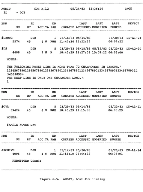
6-3 AUDIT, LO=S listing 6-4 AUDIT, LO=P listing 6-5 AUDIT, LO=L:P:N listing 6-6 AUDIT, LO=L listing
· · ·
.
.
· ·
· ·
·
· · ·
· ·
· · · ·
·
·
· ·
·
·
·
· · ·
6-7 AUDIT, LO=N Listing (AUDIT, LO=T is nearly identical) 8-1 Example of a flow trace sUInmary
.
· ·
·
8-2 Example of a flow trace recovery dump
·
·
· ·
8-3 Sample listing of ITEMIZE for a PL· ·
·
·
· ·
8-4 Sample listing of ITEMIZE for a binary library datasetwith X and NF parameters
. .
.
. · ·
· ·
· ·
·
· · ·
FIGURES (continued)
9-1 Example of a load map • • • • • •
9-2 Example of Type 1 overlay loading
9-3 Example of Type 2 overlay loading
TABLES
1-1 Permanent dataset management control statements for each
medium • • • • • • • • • •
PART 3 JOB CONTROL LANGUAGE STRUCTURES
1.
2.
3.
INTRODUCTION •
SIMPLE CONTROL STATEMENT SEQUENCES • • CONDITIONAL CONTROL STATEMENT BLOCKS •
Basic conditional block • • • Conditional block with ELSE • Conditional block with ELSEIF • • Conditional block with ELSEIF and ELSE ITERATIVE CONTROL STATEMENT BLOCKS • • PROCEDURES • • • • • • • • • •
Simple procedures • • • . Well-defined procedures • •
JOB CONTROL LANGUAGE EXPRESSIONS •
OPERANDS • •
Integer constants • Literal constants • • Symbolic variables Subexpressions
OPERATORS • • • • • • • •
Arithmetic operators Relational operators Logical operators EXPRESSION EVALUATION STRINGS
Literal strings • Parenthetic strings •
CONTROL STATEMENT BLOCKS • • • •
IF - BEGIN CONDITIONAL BLOCK ENDIF - END CONDITIONAL BLOCK
SR-OOll xv
4.
CONTROL STATEMENT BLOCKS (continued)
ELSE - DEFINE ALTERNATE CONDITION ELSEIF - DEFINE ALTERNATE CONDITION LOOP - BEGIN ITERATIVE BLOCK • •
ENDLOOP - END ITERATIVE BLOCK • • • • • EXITLOOP - END ITERATION • • • •
PROCEDURES •
PROC - BEGIN PROCEDURE DEFINITION
PROTOTYPE STATEMENT - INTRODUCE A PROCEDURE PROCEDURE DEFINITION BODY
&DATA - PROCEDURE DATA • • • • • • ENDPROC - END PROCEDURE DEFINITION
PARAMETER SUBSTITUTION • • • Positional parameters • Keyword parameters
Error messages • •
Positional and keyword parameters • Apostrophes and parentheses • • • •
FIGURES
1-1 Basic conditional block structure
. · . . ·
1-2 Conditional block structure including ELSE·
1-3 Conditional block structure including ELSEIF 1-4 Conditional block structure including ELSEIF 1-5 Iterative block structure. . . ·
4-1 Procedure definition deck structure
·
. . ·
TABLES
·
· . ·
·
·
and ELSE
· ·
·
.
· ·
· . . .
.
· .
.
.
.
· · ·
· · ·
· · · ·
·
·
·
· · ·
3-2 3-3 3-3 3-4 3-4 4-1 4-3 4-3 4-4 4-5 4-5 4-6 4-6 4-6 4-7 4-7 4-8 1-3 1-4 1-5 1-6 1-8 4-12-1 Symbolic variable table • • • • • • • • • • • • • 2-3 2-2 Expression operator table • • • • • • • • • • 2-5
4-1 Keyword SUbstitution after expansion • • • • • 4-7
4-2 Expansion of parenthetic and literal string values • 4-8
APPENDIX SECTION
A. JOB USER AREA
JOB TABLE AREA - JTA
JOB COMMUNICATION BLOCK - JCB LOGICAL FILE TABLE - LFT
DATASET PARAMETER AREA - DSP • •
B.
C.
D.
JOB USER AREA (continued)
PERMANENT DATASET DEFINITION TABLE - PDD BEGIN CODE EXECUTION TABLE - BGN •
DATASET DEFINITION LIST - DDL • • • • OPEN DATASET NAME TABLE - ODN
OPTION TABLE - OPT • • • • • • JCL BLOCK INFORMATION TABLE - JBI JCL SYMBOL TABLE - JST • • • • • LABEL DEFINITION TABLE - LOT •
LDT header Volume 1 entry Header 1 entry Header 2 entry
CHARACTER SET
EXCHANGE PACKAGE •
ERROR AND STATUS CODES
SYSTEM ERROR CODES • •
PERMANENT DATASET STATUS CODES •
FIGURES
A-I Job Communication Block (JCB)
A-2 Logical File Table (LFT) entry • • • • • • • A-3 Dataset Parameter Area (DSP) •
A-4 Permanent Dataset Definition Table (PDD) A-S Begin Code Execution Table (BGN)
A-6 Dataset Definition List (OOL) • • • • A-7 Open Dataset Name Table (ODN) • • • • • A-8 Option Table (OPT) • • • • • • • • • • • A-9 JCL conditional block information
A-lO JCL iterative block information A-II JCL Symbol Table (JST)
A-12 Label Definition Table (LDT) header • • • • A-13 Label Definition Table (LDT) volume 1 entry A-14 Label Definition Table (LOT) header 1 entry A-IS Label Definition Table (LDT) header 2 entry C-l CRAY-l Exchange Package
C-2 CRAY X-MP Exchange Package • • • • • • • • •
TABLES
D-l D-2
Error codes for reprieve processing PDD status • • • • • • • • • • • • •
GLOSSARY
INDEX
SR-OOll xvii
PART 1
INTRODUCTION
The Cray Operating System (COS) is a multiprogramming and multiprocessing operating system for Cray Computer Systems. The operating system
provides for efficient use of system resources by monitoring and controlling the flow of work presented to the system in the form of
jobs. The operating system optimizes resource usage and resolves conflicts when more than one job is in need of resources.
COS is a collection of programs residing in Cray mainframe central memory or on system mass storage following startup of the system. (Startup is
the process of bringing the Cray Computer System and the operating system to an operational state.)
Jobs are presented to the Cray Computer System by one or more computers referred to as front-end computers (also referred to as stations in Cray Research manuals). A front-end computer can be any of a variety of computer systems. Software executing on the front-end computer system is
beyond the scope of this publication.
COS includes linkages providing for the initiation and control of
interactive jobs and data transfers between the Cray Computer System and front-end terminals. These features are available only where supported by the front-end system.
The FORTRAN compiler (CFT), library routines, the CAL assembler, and the UPDATE source maintenance program are described in separate publications.
HARDWARE REQUIREMENTS
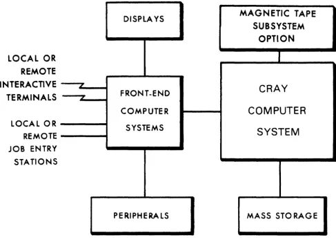
The Cray Operating System (COS) executes on the basic configuration of any CRAY-I or CRAY X-MP Computer System. Each computer system contains the following components:
• One or two central processing units (CPUs); a CRAY-I contains one CPU and a CRAY X-MP contains two CPUs.
• Central Memory. COS operates with any of four central memory size options: one-half million, one million, two million, and four million 64-bit words.
SR-OOII
Part 1
1-1 L
• A minicomputer based Maintenance Control Unit (MCU) or I/O Subsystem (lOS). The I/O Subsystem, if present, performs all required Maintenance Control Unit functions.
• A mass storage subsystem. The mass storage subsystem may consist of 00-19 or 00-29 disk drives, a Solid-state Storage Device (SSD) , or Buffer Memory (BMR). BMR storage can be accessed only through an I/O Subsystem; disk drives may be connected either to an I/O Subsystem or a CRAY-l mainframe. SSD storage is connected directly to the CRAY-l or CRAY X-MP mainframe.
• An optional IBM-compatible tape subsystem. The tape subsystem requires that an I/O Subsystem is present.
The I/O Subsystem consists of from two to four I/O processors and one-half million, one million, four million, or eight million words of
shared Buffer Memory. The optional tape subsystem is composed of at least one block multiplexer channel, one tape controller, and two tape units. The tape units supported are IBM-compatible 9-track, 200 ips, 1600/6250 bpi devices.
Figure 1-1 illustrates a basic system configuration. For more
information about CRAY-l or CRAY X-MP hardware characteristics, refer to the appropriate mainframe reference manual listed in the preface.
SYSTEM INITIALIZATION
COS is loaded into Central Memory and activated through a system startup procedure performed at the MCU or I/O Subsystem. At startup, linkage to
the Permanent Dataset Catalog (DSC) is reestablished on mass storage. All permanent mass storage datasets are recorded in the DSCJ thus, permanent datasets survive startup and the user can always assume that they are present. See part 1, section 2 of this manual for more
information on datasets.
CENTRAL MEMORY ASSIGNMENT AND CHARACTERISTICS
Central Memory is shared by COS, jobs running on the Cray mainframe, dataset I/O buffers, and system tables associated with those jobs. COS allocates resources to each job, when needed, as these resources become available. As a job progresses, information is transferred between Central Memory and mass storage. These transfers can be initiated by
either the job or by COS.
DISPlA YS
MAGNETIC TAPE
SUBSYSTEM
OPTION
LOCAL OR
REMOTE
INTERACTIVE
ICRAY
FRONT-ENDTERMINALS
"'COMPUTER
COMPUTER
LOCAL OR
SYSTEMS
SYSTEM
REMOTE
JOB ENTRY
STATIONS
PERIPHERALS MASS STO RAGE
Figure 1-1. Cray Computer System configuration
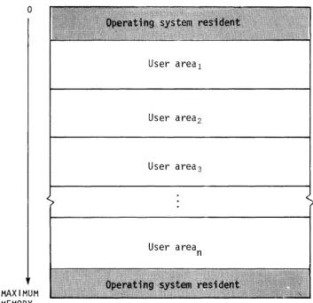
MEMORY-RESIDENT COS
COS occupies two areas of Central Memory. The memory-resident portion of the operating system occupying lower memory consists of exchange
packages, the System Executive (EXEC), the System Task Processor (STP), and optionally the Control Statement Processor (CSP). The
memory-resident portion of the operating system occupying extreme upper memory contains station I/O buffers, space for the system log buffer, and Permanent Dataset Catalog (DSC) information and buffers.
SR-OOll
Part 1
[image:22.617.60.548.104.451.2]o
MAXIMUM MEMORY
User areal
User area2
User area3
User area
n
Figure 1-2. Central Memory assignment
USER AREA OF MEMORY
COS assigns every job a user area in Central Memory. The user area consists of a Job Table Area (JTA) and a user field.
Job Table Area - JTA
For each job, the operating system maintains an area in memory that contains the parameters and information required for monitoring and managing the job. This area is called the Job Table Area (JTA). Each active job has a separate Job Table Area adjacent to the job's user
[image:23.617.111.465.55.397.2]User field
The user fietd for a job is a block of memory immediately following the job's JTA. The user field is always a multiple of 512 words. The beginning or Base Address (BA) and the end or Limit Address (LA) are
set by the operating system. The maximum user field size is specified by a parameter on one of the job control statements (see part 2, section 1) or by installation-defined default. A user can request changes in user field size during the course of a job.
Compilers, assemblers, system utility programs, and user programs are loaded from mass storage into the user field and are executed in response to control statements in the job deck. Each load and execution of a program is referred to as a job step.
A detailed description of the contents of the user field is given in part 1, section 3 of this manual. Briefly, however, the first 2008 words of the user field are reserved for an operating system/job communication area known as the Job Communication Block (JCB). Programs are loaded starting at BA+2008 and reside in the lower portion of the user field. The upper portion of the user field contains tables and dataset I/O buffers. The user field addressing limit is equal to LA-I.
Memory addresses for instructions and operands are relative to BA. The Cray mainframe adds the contents of BA to the address specified by a memory reference instruction to form an absolute address. A user cannot reference memory outside of the user field as defined by the BA and LA register contents; LA-l is the user limit. (Refer to the appropriate mainframe hardware reference manual noted in the preface for more
information.)
MASS STORAGE CHARACTERISTICS
Mass storage for CRAY-l Models A and B consists of 1 to 32 DO-19 or DD-29 oisk Storage Units (OSUs). Mass storage for CRAY-l Models S/500 or
S/lOOO consists of 2 to 32 DO-29 DSUs. Mass storage for the CRAY-l M Series, CRAY X-MP Series, and CRAY-l S Series Models S/1200 through S/4400 consists of 2 to 48 DO-29 DSUs, depending on the number of I/O Processors in the I/O Subsystem. These devices are physically
non-removable.
Although normally configured as described above, DSUs can be connected both to the mainframe and the I/O Subsystem.
All information maintained on mass storage by the Cray Operating System (except specific pre-allocated areas such as the Device Label) is
organized into quantities of information known as datasets. In
SR-OOll
Part 1
general, the user need not be concerned with the physical transfer of data between the disks and memory nor with the exact location and physical form in which datasets are maintained on mass storage. COS
translates the user's logical requests for data input and output into disk controller functions automatically. For the orientation of the user, physical characteristics of disk storage units are summarized in
table 1-1.
Table 1-1. Physical characteristics of disk storage units
Feature
Word capacity per drive
Word capacity per cylinder
Bit capacity per drive
Tracks per surface or cylinders per drive
Sectors per track
Bits per sector
Number of head groups
Latency (revolution time)
Access time
Data transfer rate (average bits per second)
Longest continuous transfer per request
Total bits that can be streamed to a unit (disk cylinder capacity)
00-19
3.723 x 10 7
92,160
2.424 x 10 9
411
18
32,768
10
16.7 ms
15 - 80 ms
35.4 x 10⁶
92,160 words
(1 cylinder)
5.9 x 10 6
00-29
7.483 x 10 7
92,160
4.789 x 10⁹
823
18
32,768
10
16.7 ms
15 - 80 ms
35.4 x 10⁶
92,160 words
(1 cylinder)
5.9 x 10⁶
[image:25.613.88.519.180.596.2]of the devices as the Master Device. The Master Device is the disk storage unit containing a table known as the Dataset Catalog (DSC), which contains information for maintaining permanent datasets.
To the user, mass storage permanent datasets are always present and available on mass storage. This permanence is achieved through
techniques permitting the datasets noted in the DSC to be recovered or reestablished in the event of system failures. Portions of COS, such as the loader, utility programs, the compiler, the assembler, and library maintenance and generation routines, reside in permanent datasets accessible by user jobs at any time.
Datasets containing job input decks and output from jobs also reside on mass storage. Because these datasets are listed in the Dataset Catalog
they are also regarded as permanent. This designation is somewhat
misleading since their permanence is by definition rather than by tenure in the system. That is, the input dataset is permanent from the time it is staged from the front-end system to the Cray Computer System until the job terminates. Output datasets being disposed to a front end are
permanent from job termination (or whenever the disposition was
initiated) until the disposition is complete. The permanence of these system-defined datasets allows them to be recovered along with other permanent datasets after a system failure.
Any user job can create a mass storage permanent dataset. It can be subsequently accessed, modified, or deleted by any other job having correct access privileges and producing the correct permission control words when attempting to associate it with the job. Permission control words are defined at the time the dataset is designated as permanent
(that is, saved).
A permanent dataset ceases to be permanent when a user with the correct permission control word deletes it. This deletion notifies COS that the space occupied by the dataset is no longer permanent. However, the space is still reserved by the dataset until it is released by the user (see part 2 sections 3 and 5, respectively, for information on the RELEASE and DISPOSE control statements) •
In addition to the various permanent datasets, mass storage is used for temporary datasets. A temporary dataset is created by the job using it and remains temporary unless it is designated as permanent, released, or disposed to a front end by the job. A temporary dataset neither saved as permanent nor disposed of is termed a scratch dataset and ceases to
exist when the job releases it or terminates.
COS allocates space to datasets as needed by tracks. Storage assigned to a single dataset can be noncontiguous and can even be on multiple disk
unit~. Default and maximum sizes for datasets are defined by system parameters. The user has limited control over the allocation of storage to a dataset through the ASSIGN control statement.
SR-OOII
Part I
MAGNETIC TAPE CHARACTERISTICS
An I/O Subsystem can include an Auxiliary I/O Processor (XIOP) with the capability of addressing up to 16 block multiplexer channels of tape
units. Each block multiplexer channel can be attached to IBM-compatible control units and tape units in a variety of configurations. The block multiplexer channels communicate with the control units and tape units to allow reading and writing data that can also be read and written on
IBM-compatible CPUs. The physical characteristics of tape devices are summarized in table 1-2. The block sizes in this table are used by the COS tape system for transparent-format tape datasets (described in part 1, section 2).
Density (bits/inch)
6250 1600
Table 1-2. Physical characteristics of 200 ips, 9-track tape devices
Transfer rate Data/2400 ft. % of reel Block size (kilobytes/sec)
1170 300
reel (megabytes)
168 43
containing (bytes) data
94 32768
DATASETS
Nearly all information maintained by the Cray Operating System (COS) is organized into quantities of information known as datasets. The
following are some of the more important factors to remember about datasets.
• The dataset medium is the type of physical device on which the dataset resides.
• The dataset structure is the logical organization of the dataset. • The dataset longevity is the retention period for the dataset.
• A dataset must be local to be usable.
• The dataset disposition code tells the operating system what action to take when the dataset is no longer local.
• Each dataset is known by its dataset name.
• Datasets are read and written using operating system requests (user I/O interfaces).
DATASET MEDIUM
Datasets can be classified by medium, as follows:
• Mass storage datasets
• Memory-resident datasets
• Interactive datasets
• Magnetic tape datasets
MASS STORAGE DATASETS
2
All datasets, unless otherwise specified, reside on Cray mass storage, that is, on mass storage attached directly to the mainframe or to the I/O Subsystem.
SR-OOll
Part 1
MEMORY-RESIDENT DATASETS
Some datasets can be specified by the user as memory-resident datasets. A memopy-pesident dataset is wholly contained within one buffer (see BS parameter on the ASSIGN control statement in part 2, section 3 of this manual) and remains in memory at all times. Such a dataset ordinarily occupies no mass storage. A memory-resident dataset is normally a temporary dataset; however, a mass storage permanent dataset can be declared memory resident.
A dataset can be declared memory resident to reduce the number of I/O requests and disk blocks transferred. Memory residence is particularly useful for intermediate datasets not intended to be saved or disposed to another mainframe. All I/O performed on a memory-resident dataset takes place in the dataset buffers in memory and the contents of the buffers are not ordinarily written to mass storage. Such a dataset cannot be made permanent, nor may it be disposed to another mainframe, unless copied to mass storage.
Normally, a memory-resident dataset is empty until written on. If an existing dataset is declared memory resident, it is loaded when the first
read occurs. A user attempting to write to a memory-resident dataset must have write permission. However, as long as the buffer does not appear full, no actual write to mass storage ever occurs. Therefore, changes made to an existing dataset declared memory resident are not
reflected on the mass storage copy of the dataset.
A memory-resident dataset must be defined through an ASSIGN control statement containing the MR parameter or through an F$DNT call to the system. If the F$DNT call is used, the Dataset Definition List (DDL) supplied should specify DDMR=I. (See the description of the ASSIGN
control statement in part 2, section 3 of this manual.) In addition, the buffer size parameter should specify a buffer large enough to contain the entire dataset plus one block.
If at any time the system I/O routines are called to write to the dataset and the buffer appears to be full, the dataset ceases to be treated as memory resident, the buffer is flushed to mass storage, and all
memory-resident indicators for the dataset are cleared.
Magnetic tape, execute-only, and interactive datasets cannot be declared memory resident.
INTERACTIVE DATASETS
Instead, records are transmitted to and from a terminal attached to a front-end station. Record positioning (for example, REWIND or BACKSPACE)
is not possible.
Interactive datasets can be created by interactive jobs through the use of the ASSIGN control statement or F$DNT system call.
MAGNETIC TAPE DATASETS
A magnetie tape dataset is available to any job declaring tape resource requirements on the JOB statement and specifying the appropriate
information on its ACCESS request.
A magnetic tape (referred to in this manual as a magnetic tape dataset) can be unlabeled (NL), ANSI standard labeled (AL), or IBM standard
labeled (SL), and can be recorded or read at either 1600 or 6250 bits per inch (bpi). To gain access to an existing tape dataset for reading
and/or rewriting, the correct file identifier (permanent dataset name), the desired device type, and, optionally, a volume identifier list must be specified. The volume identifier list can consist of 1 to 255 volume identifiers. If the permanent dataset name (PDN) is omitted from the ACCESS request, the local dataset name is used as the file identifier.
To gain access to a tape dataset for creating, the file identifier, desired device type, and the NEW parameter option must be specified on the ACCESS request. If no file identifier is present, the local dataset name is used. If the volume identifier list is missing from the access request, it is called a non-speeifie volume alloeation. A speeific volume alloeation occurs when the volume identifier list is present at the time of the access request. New tape datasets must be written to before a read is allowed.
Other options describing the tape dataset are available from the access request. See the ACCESS control statement description (part 2, section 4 of this manual) for more details. Using other parameter options allows more efficient tape dataset descriptions.
COS automatically switches volumes during dataset processing and returns to the first volume of a multivolume dataset in response to a REWIND command. If a permanent write error occurs when trying to write a tape block for the user, COS automatically attempts to close the current volume and continues to the next volume.
The COS tape system uses Buffer Memory as a tape block buffering area so that the job's I/O buffer need not be as large as the tape block (as with other operating systems). This technique can result in significant
memory savings whenever large tape blocks are being processed and in increased transfer rates whenever smaller blocks are being processed. The advantage in having a large COS buffer is a reduction in the overhead in the tape subsystem.
SR-OOll
Part 1
DATASET STRUCTURE
COS supports several dataset structures:
• Blocked format
• Interactive format
• Unblocked format
• Tape formats (interchange or transparent)
BLOCKED FORMAT
Blocked format is used by default for external types of datasets, such as user input and output datasets. Record positioning requires a blocked format. The blocked format adds control words to the data to allow for processing of variable-length records and to allow for delimiting of levels of data within a dataset. A blocked dataset can be composed of one or more files, which are, in turn, composed of one or more records. Figure 2-1 illustrates the data hierarchy within a dataset.
Dataset
Record
2Figure 2-1. Data hierarchy within a dataset
Blank compression
Blank fields can be compressed for blocked coded files. Blank field compression is indicated by a blank field initiator code followed by a count. The default blank field initiator code is defined by the
installation parameter I@BFI which is either an ASCII code or 7778 indicating that blank compression will not be done. Blank compression can be inhibited using an ASSIGN statement parameter or an F$DNT system call. A blank field of 3 through 96 characters is compressed to a
2-character field. The count is biased by 368 ; the actual character count is limited to 418 ~ eharaeter eount ~ 1768 (the ASCII graphics) •
Block control word
The block control word (BCW) is the first word of every 5l2-word block. The format of a block control word is depicted in figure 2-2.
Field
M
BDF
BN
FWI
o
8 16 24 32 40 48 56 63MI////////I 1/////////////////1 BN I FWI
BDF
Figure 2-2. Format of a block control word
Bits
0-3
11
31-54
55-63
Description
Type of control word (for block control word, M=O)
Bad data flag; indicates the following data, up to the next control word, is bad. This flag is set by the I/O Subsystem for magnetic tape datasets in interchange format.
Block number. Designates the number of the current data block. The first block in a dataset is block O.
Forward index. Designates the number of words (starting with 0) to the next record control word or block control word.
Record control word
A record control word (ROW) occurs at the end of each record, file, or dataset. The format of a record control word is illustrated in figure
2-3.
SR-OOll
Part 1
Field
M
UBC
TRAN
BDF
PFI
PRI
FWI
BDF
o
8 24 32 40 48 56 63MI UBC I PFI PRI FWI
Figure 2-3. Format of a record control word
Bits
0-3
4-9
10
11
20-39
40-54
55-63
Description
Type of control word: 108 End-of-record (EOR) 168 End-of-file (EOF) 178 End-of-data (EOD)
Unused bit count. For end-of-record, UBC designates the number of unused low-order bits
in the last data word of the record terminated by the end-of-record. For end-of-file and end-of-data ROWs, this field is
o.
The data area protected by UBC must be zero-filled.Transparent record field; used for an interactive output dataset only. If set,
substitution of end-of-record ROWs is suppressed.
Bad data flag; indicates the following data, up to the next control word, is bad. This flag is set by the I/O Subsystem for magnetic tape
datasets in interchange format. If flag is set, an irrecoverable error was encountered in
following data.
Previous file index. This field contains an index modulo 220 (20,000,0008) to the beginning of the file. The index is relative to the current block such that if the beginning of the file is in the same block as this ROW, the PFI is 0.
Previous record (ROW) index. This field
contains an index modulo 215 (100,0008) to the block where the current record starts. The
index is relative to the current block such that if the first word of data in this record is in the same block as this ROW, PRI is
o.
Disregarding block control words occurring at Sl2-word intervals in a dataset, RCWs have the following logical relationship in a dataset.
An end-of-record RCW immediately follows the data for the record it terminates. If the record is null, that is, if it contains no data, an end-of-record ROW can immediately follow an end-of-record or end-of-file RCW or can be the first word of the dataset.
An end-of-file ROW immediately follows the end-of-record ROW for the final record in a file. If the file is null, that is, if it contains no records, the end-of-file ROW can immediately follow an end-of-file RCW or can be the first word of the dataset.
An end-of-data ROW immediately follows the end-of-file ROW for the final file in the dataset. If the dataset is null, the end-of-data RCW can be the first word on the dataset.
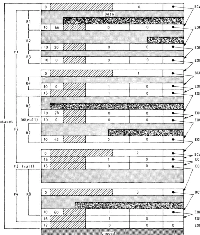
The typical dataset has many end-of-record RCWs per block. An example of dataset control words is illustrated in figure 2-4. In this example, a dataset is contained within four physical sectors, each beginning with a BOW (thus the four BOWs in this example are numbered 0, 1, 2, 3). The dataset contains four files shown as Fl, F2, F3, and F4. Fl contains the four records shown as RI through R4; F2 contains records RS through R7; F3 contains no records at all; F4 contains record R8.
INTERACTIVE FORMAT
Interactive format closely resembles blocked format; however, each buffer begins with a block 0 BOW. Each record transmitted to or from COS by an F$RDC or an F$WDC call must contain a single record consisting of a BCW, data, and an end-of-record ROW.
Two formats for interactive output can be assigned when the dataset is created: character blocked and transparent. Character blocked mode is the default. In character blocked mode, an end-of-record RCW is
interpreted as a line feed or a carriage return. In transparent mode, the end-of-record RCW is ignored and the user is responsible for
supplying carriage control characters.
UNBLOCKED FORMAT
Dataset I/O can also be performed using unblocked datasets. The data stream for-unblocked datasets does not contain Cray Operating System record control words (RCWs) or block control words (BOWs).
SR-OOII
Part 1
Fl
Dataset
F2 R5
L
R6(null)
I
R7
L
Figure 2-4. Example of dataset control words (octal values shown)
Bew
EOR
EOR
EOR
Bew
EOR
EOF
EOR
EOR
EOR
BeW EOF EOF
Bew
[image:35.620.109.518.122.601.2]The system does not allocate buffers in the job's I/O buffer area for unblocked datasetsi the user must specify an area for data transfer. When a read or write is performed on an unblocked dataset, the data goes directly to or from the user data area without passing through an I/O buffer. The word count of data to be transferred must be a multiple of
512.
Unblocked I/O cannot be performed on an interchange format tape dataset (see below).
TAPE FORMATS
Tape datasets are written and read on tape volumes. A tape voLume is a reel of tape. A tape volume is also known as a dataset section (for example, in FSEC= on the ACCESS statement).
Data is read or written in tape blocks. A tape bLock is a unit of data recorded on magnetic tape between two consecutive interblock gaps. The size of tape blocks can vary from one byte to a maximum of approximately one million bytes.
Tape datasets can be read or written using two different formats:
interchange or tpansparent. Tape datasets can also be labeled or unlabeled.
Interchange format
Interchange format facilitates reading and writing tapes that are also to be read or written on other vendors' systems. In intepchange fopmat,
each tape block of data corresponds to a single logical record in COS blocked format (that is, the data between record control words) •
In interchange format, tape block lengths can vary up to an
installation-defined maximum which cannot exceed 1,048,576 bytes (131,072 64-bit words). It is recommended that the maximum block size not exceed 100 to 200 kilobytes. Blocks exceeding these sizes may require special operational procedures (such as the use of specially prepared tape
volumes having an extended length of tape following the end-of-tape (EOT) reflective marker) and yield little increase in transfer rates or storage capacity.
When a tape dataset is read in interchange mode, physical tape blocks are represented in the user's I/O buffer with block control words (BCWs) and record control words (RCWs) added by COS. The data in each tape block is terminated by an ROW. The unused bit count field in the RCW indicates the amount of data in the last word of the tape block that is not valid data. A BCW is inserted before every 511 words of data, including the RCWs. The formats of RCWs and BCWs are described previously in this section and shown in figures 2-2 and 2-3.
SR-OOll
Part 1
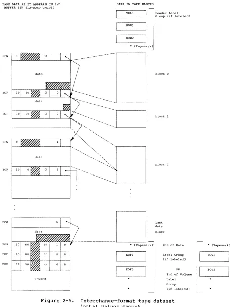
Figure 2-5 depicts a tape dataset in interchange format. Tape blocks within tape label groups are not included in this format. The end of the dataset is represented by an end-of-file (EOF) ROW followed by an
end-of-data (EOD) ROW.
When a tape dataset is written in interchange format, the data must be in the I/O buffer in the user field in COS blocked format. The data in each logical record is written as a single tape block. BOWs and ROWs are not recorded on tape. BOWs within a record are discarded and the unused bits and terminating RCW are also discarded. The unused bit count must be a multiple of 8. Tape datasets written in interchange mode must consist of
a single file (single EOF ROW). Multiple-file tape datasets are not supported in interchange mode.
Transparent format
In transpapent format (disk image), each tape block is a fixed multiple of 4096 bytes (512 words), generally based on the dataset density (that is, 16,384 bytes at 1600 bpi and 32,768 bytes at 6250 bpi). The data in the tape block is transferred unaltered between the tape and the I/O buffer in the user field: no control words are added on reading or discarded on writing. In transparent mode, the data can be in COS
blocked format or COS unblocked format. Transparent format tapes are not generally read or written by other vendors' equipment.
DATASET LONGEVITY
Permanent datasets are retained by the operating system until instructed otherwise. All other datasets are considered temporary.
TEMPORARY DATASETS
A tempopary dataset is available only to the job that created it.
Temporary datasets can be created in two ways: either explicitly by use of the ASSIGN control statement, or implicitly upon first reference to a dataset by name or unit number on an I/O request or an OPEN macro call.
A temporary mass storage dataset is empty until written on. Rewind or backspace of the dataset is necessary before it can be read. A temporary dataset can be made permanent by use of the SAVE control statement. If
TAPE DATA AS IT APPEARS IN I/O BUFFER (IN 5l2-WORD UNITS)
BCW
data
EOR 10
EOR 10
BCW
EOR 10
BCI-I
EOR 10 60
EOF 16 00
EOD 17 no
unuspo
Figure 2-5.
SR-OOll
DATA IN TAPE BLOCKS
VOLl
HDRl
HDR2
* (Tapemark)
---
---* (Tapemark)
EOFl
EOF2
Header Label Group (if labeled)
block 0
block 1
block 2
last data
block
End of Data
Label Group (if labeled)
OR
End of Volume
Label
Group
(if labeled)
Interchange-format tape dataset (octal values shown)
Part 1
2-11
* (Tapemark) EOVl
EOV2
[image:38.612.84.541.64.671.2]PERMANENT DATASETS
Only mass storage or magnetic tape datasets can be permanent.
Magnetic tape permanent datasets
Tape datasets are discussed under Dataset Media earlier in this section.
Mass storage permanent datasets
A mass storage permanent dataset is available to the system and to
other jobs and is maintained across system startups. Permanent datasets are of two types: those created by SAVE requests made by the user or front-end system (user permanent datasets), and input, output, or COS internal datasets (system permanent datasets).
User permanent datasets are maintained for as long as the user or
installation desires. They can be protected from unauthorized access by use of permission control words and ownership values.
When a user permanent dataset is accessed via an ACCESS control statement (see part 2, section 4 of this manual), it is treated as a local dataset by the job requesting access. However, it still exists as a permanent dataset on the system and can be used by other jobs unless unique access
to that dataset was granted. If any information in an existing permanent dataset is overwritten or if the size of a permanent dataset is changed, an ADJUST should be performed on that dataset (see part 2, section 4 of this manual). An ADJUST is performed automatically when a permanent dataset is released.
System permanent datasets relate to particular jobs or reflect the current operational state of COS. A job's input dataset is made permanent when the job is received by the Cray Computer System and is deleted when the job terminates. Output datasets local to the job can be disposed while the job is running or can be automatically made
permanent when the job terminates and then deleted from the Cray Computer System after being sent to the front-end system for processing. An
example of a system permanent dataset is the system log.
An exeeute-only dataset is a user permanent mass storage dataset for which all forms of examination and modification by users are prohibited. An execute-only dataset is loaded by the Control Statement Processor
(CSP) for execution. It differs in usage from other user permanent datasets in several ways:
• While an execute-only dataset is loaded in memory, no DUMPJOB requests are honored.
• The dataset cannot be staged via a DISPOSE request.
• The dataset must be loaded by a dataset name call rather than by the LOR control statement.
• The dataset cannot be dumped via PDSDUMP for archiving purposes.
Because execute-only is a dataset state rather than a permission mode, it is advisable to set, at minimum, a maintenance permission control word to disallow modification or deletion of the dataset.
LOCAL DATASETS
A dataset to which a job has access is a LocaL dataset. A local dataset can be temporary or permanent. Permanent datasets are made local with the ACCESS control statement or the ACCESS library subroutine (described in the Library Reference Manual, CRI publication SR-OOl4). If the
dataset referenced is a tape dataset, the device resource must also be specified on the JOB control statement (see part 2, section 2 of this manual) •
DATASET DISPOSITION CODES
Each dataset is assigned a disposition code telling the operating system the disposition to be made of the dataset when the job is terminated or the dataset is released. The disposition code is one of the parameters of the DISPOSE and ASSIGN control statements (see part 2, section 3 of this manual).
Each disposition code is a 2-character alphabetic code describing the destination medium of the dataset. The default disposition code for a dataset is SC (scratch) when a dataset is opened, unless the dataset named is one of a group of special names such as $PLOT, $PUNCH, and $OUT. By default, COS assigns the disposition code PR (print) to $OUT when the dataset is created. No DISPOSE statement is required for $OUTi
it is automatically routed back to the originating mainframe with a PR (print) disposition.
SR-0011
Part 1