$$$$ :b :II $ $ $ $ $ $ 3>
$ ~ .$ $ $ $ $$$.$ 31$$!b$ !ll $ $$~$ $ $ $$lb$$ :ll$$$ :b :J, $
$ ~:ti
!h $
$:1;.$$
$$$
~ ;b $ 1> $ !b
&. $
S $
!fl,£' $
USER=EGU GU~UE=LPT UEVICE=@LPA
BEw=151 QPRI=127 LPP=63 CPL=80 COPIES=l Ll~IT=153
$$~ $~$ :s
;b $ $ $
ill $ ~
111 ~ ;j) $ ;iI 1£
;£ $ ;j;, s,
;y,~;), :i!$$
CREATED:
ENI;.LJE.UE.O: PRIf~TIN(;: 31-AUG-77 21-DEC-77 21-DEC-77 11:16:£12 13:3,,:30 13:38:31.l PATH=:UDU:EGO:DUCUMENT.LS $ $ $ $;£,$$$ $ $ ~$$$$ $ $$ $$ $ $$ $ $$ ~ ~, $ ~ :t. $ $ ;1)
$ ~ :£. $ $$$$ $ ;t.$ ;I)
$ ;ji :2, $ $ ~ ~
$ ~ $ $ $ :£. ~
$$$ .$ 3! $$;1.$$ !b J., :fi
AOS XLPT REV 01.00
$ :!> $
~
$ $f, :£
:bSl $$$$~
CHAPTER 1 - Introduction • • •
..
1.1 Address Structure. • • • •
1.2 Available Req;st~rs • • • •
1.3 Data Aodress Formation • • •
1.3.1 General Adoress;n~ • • •
1.3.2 Register Aodress;ng • •
1.3.~ Local Variable AddresSing.
1.3.~ Argument AOdressing. • •
1.3.S Data Indirection • • • •
1.3.6 Character String Addressing
1.3.7 bit Adoressing • • • •
1.4 Procedure Adaress;ng. • • •
1.~.1 Procedure Indirection • •
1.4.2 Gate Array. • • • • •
1.~ Stack Structure • • • • •
l.b Opcode Format • • • • • •
CHAPTER 2 - Data Types and Formats
2.1 I:.iasic Allowable lypes
2.1.1 Floatinp Point
2.1.2 Fixed • • 2.1.3 Logical. •
2.1.4 unsiqnen •
2.1.5 Character •
2.1.6 Commercial.
2.2 Rounoing • • •
• • • • • •
CHAPTER 3 - lnstruction Set
• • • • • • •
3.1 Introduction • • •
3.2 Signed Fixpd ~o;nt •
3.2.1 16 dit Fixed Point
3.2.1.1 <REr>I<REf> • 3.2.1.2 <REF>I<r~~ED>
3.2.2 32 oit rixed Point
3.2.2.1 <REF>I<kEF> •
3.2.2.2 <REF>I<lMME0>
3.3 Unsigned. • • •
3.3.1 Uns;~ned 8 bits
3.3.1.1 <~EF>I<RtF>
3.3.1.2 <REF>I<I~MED>
3.3.2 Unsigned 32 Bits. •
..
• •..
• • • • • • • • • • • • • • • • •..
•..
•..
..
..
•..
•..
•..
•..
..
•..
• •..
..
..
..
• •..
..
..
..
• •..
..
..
• • • • •..
•..
..
•..
..
•..
..
..
..
..
•..
..
•..
..
• • •..
•..
..
..
..
• • • • • • • •..
..
..
..
..
..
..
• •..
..
..
..
..
..
..
•..
..
..
..
•..
•3.3.2.1 <REF>I<REF>
3.1.2.2 <REF>/<lMMED> 3.4 Floating Point. •
3.4.1 8inqle Precision
3.4.2 Double Precision
3.5 Character .. • ..
Floating Point
Float;n~ Point
3.6 Sit • • .. .. •
3.b.1 Single dits
3.0.2 Multi-bit
3.6.3 Bit Numeric
..
3.7 Commercial .. ..
3.8 titack Manipulat,on
3.9 Jumps.. • • ..
3.9.1 Entry and Exit
3.9.2 vanilla Jumps
..
..
..
•..
•..
•..
• •..
• •..
•II
..
..
..
..
..
..
•..
•..
..
..
• •..
..
..
..
•..
..
..
..
..
•..
•..
•..
• • •..
..
•..
•..
• •..
•..
..
..
..
..
..
..
•..
..
..
•..
..
• •..
..
•..
•..
..
..
•..
..
..
..
..
..
•..
..
..
•..
..
..
..
•..
..
..
..
..
•..
..
..
..
..
..
•..
..
•..
..
..
•..
..
..
..
..
..
..
•..
..
..
•..
..
..
..
• •..
• • •..
..
..
•..
..
..
• •..
•..
•..
•..
• • •..
..
..
•..
..
..
..
..
..
..
•..
• •..
•..
•..
..
..
..
..
• •..
..
..
..
•..
•..
•..
..
..
..
..
..
..
•..
• to
..
..
•
..
• • •..
..
..
•..
•..
• • • •..
•..
..
•..
•..
• •..
..
• •..
• • •..
..
•..
..
..
..
..
•..
..
..
..
..
•..
..
..
..
..
•..
..
..
•..
• • •..
•..
•..
..
• •..
..
..
• • • •..
..
..
•..
..
..
..
• • • • • • • • • • • • • • • • • • •..
• • • • • • • •..
• • • •..
•..
..
..
..
..
..
..
..
1-1 1-1 1-1 1-3 1-3 1-4 1-4 1-5 1-5 1-5 1-6 1-7 1-7 1-8 1-9 1-11• <:-1
.. 2-1 • 2-1 • 2-1 .. 2-1 • 2-1
.. 2-2
• 2-2 .. 2-2
..
.. 3-1 • 3-1 .. 3-1 • 3-2 .. 3"'3 • 3-4 .. 3-4 • 3-5
• 3-6 • 3-6 .. 3-b
.. 3-7 • 3-9 • 3-9 • 3-10
• 3-11
3.9.3 Dispatcnes •
..
..
• •..
..
..
•..
..
..
3-25 _~ • 10 Conversion..
..
..
..
..
•..
..
..
..
..
..
..
..
3-27 3.11 f.ieserved Instructions..
..
..
..
..
..
..
..
..
3-283.1d tiystem control
..
•..
..
•..
..
• 3-28.) .. 13 lliPut Il)utput
..
..
..
..
..
..
•..
..
..
..
..
..
3-28:3. 14 M; sce 11 8I"leO'JS
..
..
..
•..
..
..
..
..
..
..
..
..
3-28CHAPTi:.i< 4
-
Interrupts and Traps..
..
•..
..
• •..
• 4-14.1 Gelieral •
..
•..
•..
..
•..
..
•..
..
4-14.2 Procedure Traps
..
..
..
..
..
..
..
..
..
4-24.3 ,",rocess Traps
..
• • •..
•..
..
..
•..
..
..
4-2i.I.4 SYstem Traps
..
..
..
..
..
..
..
..
..
..
..
..
4-2CHAPTtK '5
-
Protection..
..
..
..
..
•..
..
..
..
·
5-1S .. 1 General
..
..
..
..
..
..
•..
..
..
..
..
5-15.2 Ring Maximization • •
..
..
..
..
..
..
..
..
..
5-15.3 Determination of the Current Ring of Execution
..
..
5-25.4 Stacks
..
..
• • •..
..
•..
•..
• • 5-2Ch.4PTER b
-
"';emory f-! a 1"\ ape men t..
..
..
•..
..
..
•..
..
b-1CH.AP1E:.R '7
..
I/O System..
..
..
..
..
..
..
..
..
..
..
..
7-1 7 • 1 Organization •..
..
..
..
..
..
..
..
..
• 7-17.2 ubjectives for the EGO-1 I/O system
..
•..
•..
• 7-3 CHAPTER 8-
A v eo ; I a b i 1 i t Y IRe 1 ; ab i 1 ; t y I '''1 a; n t a ; nab i 1 ; t y •" 8-1
8" 1 Uverview
..
•..
• • • •..
..
..
8-18.2 EGO D;agnostic Control Processor Objectives •
..
" 8-1This ;s not the eno.
It ;s not even the beginning of the end. aut i t is the eno of the beginning.
winston Church; 11
Data General Corporation
Company Confidential
-1
11:3:37
31/Augl17
Data General Corporation Company Confiaential
-2
11:3:37
31/Aug/77
-3
Data ~eneral, to eccomodate ,ts present customer's growth
requirements and expand its sales base, must develop a medium scale
architecture for near ter~ use. This arc~itecture w,ll alleviate
the logical adaress space limitation evidenceo ;n the Eclipse line,
and will provide a contemporary arChitectural foundation for a ne~
line of small and ~edium scale systems.
1. fhis medium range arc~itecture will allow for implementations
from low cost silicon to hi9~ performance multi·unit
processors.
2. It will have a large logical address space· somewhere in the
range from B megabytes (2**23) to U billion bytes (2**32).
3. The desiqn will be extensicle for future enhancement both in the
instruction set and the architectural organization.
4. There will be upwara and downward compatibility at the object
code level. This will enable us to provide a sinple code
generator and run time library for each lan9UaQe, and to
proviae program transportaoility in a network environment.
5. The basic orientation of the machine is for user programming in high level languages (COBOL, FORTRAN, RPG, etc.)
6. SPL will be an inteqral part of the machine environment. All
software should be ;mplementaole in SPL.
7. There will be no architectural limit on file stora8e capacities.
1. The machine will be released to manufacturing e~gineer;ng in 14
months ana be aeliverahle within 20 months of project
startup. This implies a straightforward implementation.
2. Tnrough use of ~ood e~g;neer;n9
w;ll strive for intrinsic
practice, the
reliability to
Data General Corporation Company Confidential
implementation provide good
11:3:37
31/Aug/77
-4
availibilityand low MTTR. Self diaqnostic capabilities wi1 I be provided.
3. hisk will be minimized by utilization of existing circuit design
(E/SOU FPU), packaging schemes (E/250), and mature technol-ogies (TTL) wnere possinle.
~. ~ew circuit aesigns
Max Boards Max Cost
CPU (including cache) Aadress Translation Unit
Console Controller (w/Micro-Nova)
SC ~pmory Controller (1 per 2 Mb)
250K Hyte SC Memory w/E~CC
4
1 1 1 1
$
Existing circuit designs requiring modification:
Migh Speea C~annel E/500 FPG
5. Eclipse compatibility will be provided at the user level by a processor mode, thus enabling per process selection of Eclipse e~ulat;on. Performance in this mode will be max;m-ized subject to the overall time constraints on the project. (Target improvement is 25% faster than the E/SOO).
Emulation of the ~/SOO map is under investigation. This capability, which would proviae operating system transpor-tability from the Eclipse, will be included if possible. It is anticipated trat the tclipse compatibility will not be included in later implementations.
b. The 1/0 DUS will be compatible with the Nova and Eclipse 110 cus, data channel bus, and high spee~ channels.
7. The 110 bandwiath will have the same ma9nitude as the memory
bandwidth.
8. The data pathS for fixed point arithmetic will be 32 bits wiee.
9. Hardware features (especially accelerators) that are to each market seqment will be modularized so machine can be economically configured for
functions.
Oata General Corporation Company Confidential
applicable that the various
10. As muCh software as possible will be written in SPL. The only constraint on this objective will be the availibitiy of the SPL compiler and debugger.
1. The prOduct will provide a ~raceful up~ard growth path from tne Eclipse c/500 series in terms of immediate performance improvements and long term conversion to the faster, higher capaoility native mode.
2. Although the initial implementation will provide a high end for Data General's product line, it is anticipated that future implementations wi 11 be less expensive, ano thus, when the FhP arrives, this architecture ~ill provide a high level
langua8e compatiole lower end for the product 1 ina.
Uata General Corporation Company Confidential
11:3:37
31/Aug/77
CHAPT~R 1 - Introouction
1.1 Address Structure
The EGO architecture supports a
aodress space of 51? million bytes.
into 128 segments, each containing
segment can contain either proceoure
process wide, two
This total space
up to 4 million
or data.
oimer"ls;onal ;s divided
bytes.
A
The basic addressinQ granularity ;s to the byte. The address
mechanism of the memory system is always preser"lteo with e "virtual
address comprised of segment and oyte offset within the segmer"lt.
This logical address is 29 bits in length. (See Memory Management
ChaPter for a detailed description of me~ory management and the
translation of the logical address to a Physical address).
1.2 Available Registers
The processor contains the followinA
available to the programmer for use ~ith the
set:
classes of registers
standard instruction
*
Sase hegisters (~R) • The 8 base repisters are 32 bits wideand contain a byte pointer. bits 0-2 of this pointer
represent a ring number, bits 3-9 a seQment number, and
bits 10-31 a byte offset. base register O;s the Program
Counter (PC), SRi the Frame Pointer (FP) , and ~R2 the
argument LinkaQe Pointer (LP). base register 0, the PC,
can only oe mocified as a result of a branch type
instruction. In all other cases, an attempted mooificat;on
of
BRO
;s inhibited and signalled as an error conaition.*
Inde~ ~eg;sters (XR) - Eight 32-bit ;noex registers areprovided.
*
Accumulators (Ae) - There are eiqht 32-b;t accumulators foruse in f;xad or floating point operations. 32-b;t signed
or unsigned tixeo point numbers or single precision
float-inq point numbers can be movpd to the AC's directly.
1e-bit signed fixed point values are sign extended to
32-bits on a move to an AC. a-bit unsigned values are zero
Data General Corporation
Co~pany Confidential
1.2 Available Registers 1-2
extenaed to 32-bits on a move to an AC. Double precision floating point values may only be movea to an even-odd pair of AC's providin9 four dOUble precision floating point accumulators numbered zero two, four and six. Character data types and commercial data types may not be moved to an AC. Bit data types may only be moved to an AC us;np the bit numeric type moves on a bit field of no more than 32 bits.
The precedin9 registers are maintained on a per procedure oasis. ~hen a new procedure is called, the registers are saved, ano their initial values in the new procedure are indeterminate. On a return, the old values of tne registers are restored.
In addition to the rep;sters, there is a process wioe control register calleo the Procedure Status Register (PSR), which can only be mooified using privileged instructions. This register contains:
A cond,tion register (CR) whicn oeserioes the condition of the results of all operations performea within the ALU.
Rounding mod~ bits to define the type of rounding to be performeo at the end of floating point arithmetic operations.
Trace bits to oefine procedure tracing to oe performed.
Emulator mode bits defining the instruction set currently being executed.
Procedure trap inhibit bit.
System trap inhibit bit.
Privileged instruction enable bit.
The PSR is saved through traps, but is not saved cedure call. ~hen a new procedure segment is invoked, these bits are automatically set from values in descriptor.
Data General Corporation Company Confidential
on a pro-certain of the segment
11:3:37
31/Aug/77
Data Address Formation
1.3 Data Address Fcrmation
An EGU operand reference ;$ self describing and falls into one of tour categories: general, register, local variable, and arqument. Each of these cate~ories permits indirect addressing, spec,fied when the
"5"
bit is set. (except index and accumulator register specification in the register adoress cate~ory)1.~.1 General Addressing
The following formats are used for general address generation:
8R byte I-Ielative (signed disp)
t3R !}yte Relative (signed cisp)
oR
tSyte ~elat;ve(posit;ve disp)
--~-~-~--~-~--~~~--~-~~-~~
1110lti1l BR I XR lDISP (7) I
---
o
1 2 3 4 5 b 7 8 9 151111101 BR I xR InljDISP (lc.i)
-
..
o
_---1 2 3 4 ~ b 7 8 9 10 23
1111111 oR I xR I@IDISP (22)
---_.---
o
1 2 3 4 5 6 7 8 9 IV 31
Each of these formats contains a case register field
caR),
an index register field (XR), and a displacement field. An effective address ;s constructed hy first summing the offset from the speci-fied SR, the low order 23 bits of the Xk and the displacement field sign extended to 23 bits (in the 32 oit for~, the displacement fiela is zero extend~c to 23 bits). If the XR field is zero, no index register is used in the computation. If the result ;s greater than 2**22, a segment overflow trap is qenerated. Otherwise, the result ;s concatenated with the segment number from the bR to form the effective aOdress. In all cases of cyte addressing, bits 0-8 ofthe specified XR are ignored during the aadress generation cycle.
~hen PC relative aodressing is specified CBRO), the value of the PC
used is the address of the first opcode oyte.
Data General Corporation Company Conf;aent;al
11:3:37
31/Aug/77
1 .. 3,,2 Register Addressing
1.3.2 Register Addressing
The BRs, XRs, and accu~ulators (ACs) are addressed using the followinq formats:
8ase r<eqister 10101(1110)1 Sf.<,
----~---
o
123 4 5 b 7Index Rep;ster 10101010101 XR I
~~---~-~---
o
1 2 3 1.1 ':> b 7
Accumulator 10101010111 AL I
---~---
o
1 i 3 4 S b 71.3.3 Local Variable Adoressinq
Local variables in the stack frame can be addressed using the following abbreviated format:
10' 1 I OJ I FP+
---The FP+ field is interpreted as a word offset relative to BR1, the frame pointer. Thus, the effective address is formed by shif-t,ng the FP+ field left two bits (forming a oyte displacement) and adding it to the frame pointer offset.
Data General Corporat1on Company Confidential
11:3:37
31/Aug/77
1.3.4 Argument Address;ng 1-5
1.3.4 Ar9ument Addressinq
Arguments passed to a subroutine can be addressed using the following abbreviated for~at:
Linkage Pointer V,or'; Positive
IOIOlll.:iJ1 ARG
..
o
---1 2 3 4 7
The ARG fielo is interpreted as a word offset relative to BR2,
the linkage pointer. Thus, the effective address is formeo by
shift,n~ the AK~ field left two b1ts (forming a oyte displacement)
and adding it to the linkage pointer offset.
1.3.~ uata Indirection
~hen ;nd;rection is specified, the eff~ctive address points to
a byte data pointer in memory, used to address the desired operand. The format of that pointer is:
I<Ring>1 <Seg #> I<Se~. Offset> Byte Data
Pointer
---~---~~~--
o
2 3 9 101.3.~ Character String Ao~ress;ng
To facilitate 8eneral purpose string ooerat;ons, a string addressing oescriptor has been defined which contains all necessary
information~about a character string. The descriptor has the
fol1o~;ng format:
Data General Corporation Company Confidential
11:3:37
31/Aug/77
1.3.b Character Strin~ Addressing
8yte String ~yte Data Pointer
I __ """""' ________ .. _ ... _~-... --..,.,,-.... --... --.... ---... __ .. --_I
Descriptor 16-bit max length I 16-bit current lengthl
,~~~---~~-~-
___
~__ I ______
--~---~_~_~IIJ • 1:> 10 31
1.3.7 Bit Addressing
It is necessary to builo some form of bit aooressability upon
a native byte addressable structure. The form this support takes is invisiole to the aderess portion of the memory system. The underlying addressing mechanism within the orocessing unit performs
the necessarY transformati~n between bit and byte and the necessary extraction of a cit alipned field from the byte aliqned operand.
A bit aderess is proauceo in one of two manners: with or
without inoirection. ~hen indirection is not specified, the contents of the displacement field and index re9ister (if indexing is specified) are acaeo together to form a bit offset relative to the byte pointer contained in the soecified base register.
If indirection is specified, the oisplacement and register are interpreted as byte offsets as in a regular address. The byte address generatea points to a descriPtor
the follow;n~ format:
Byte Uata Pointer !:}it Pointer
oit offset
index data with
The first wora is a byte oata oointer. The second word is a
bit offset relative to the byte specified in the paired pointer. the bit offset relative to the byte pointed to by this pointer.
Data General Corporation Company Confidential
1.4 Procedure Addressing 1-7
1.4 Procedure Addressing
The fol10w;np formats are used to generate a procedure adoress:
PC byte Relative
~R Syte Relative (signed disp)
~R Byte Relative (s;qned disp)
BR byte Relative (positive disp)
101 uF-f::>E1
---
o
1 2 3 4 5b 7
_ .... _-.ro .... _ ... _ _ _ _ ... _ _ .... _ _ .... _ ... _ _ _ _ _
IliOliiil Bf< I xH IDI5P (7) I
-~--~---~-~---
o
1 2 3 4 5 6 7a
9 15I 1 I 1 I 0 I b R I X f( i ,il I f) I S P (14 )
--.---.---.---~---
o
1 2 3a
5 b 7 8 q 101111111 aR I XR 1,IIDISP (22)
--~---.---
o
1 2 3 4 5 b 7 8 q 10 31All forms except the 8 bit form are equivalent to a data selaress formation. The evaluation of aisplacement fields, base register, and indexing are the same. The 8 bit form has an implieo case of BRO, tne PC, ana has a signed byte offset relative to that base. The value of the PC usee is the address of the first opcode byte.
1.4.1 Procedure Indirection
~hen indirection ;s specified, a procedure pointer is fetched
from memory_ This pointer is used to aoaress the target of the instruction. The for~at of a procedure pointer reached by indirec-tion is;
Data General Corooration Company Confidential
11:3:37
31/Aug/77
Procedure Indirection 1-8
---
...
-
...
----
...
...,.-...,..,....
--
...
-.---
...
-~..-.-.--I ''''ODE -~..-.-.--I <SEl:i#> -~..-.-.--I FII:LU
---~---0 2 3 '-I 1U .H
Mode bits (0-2) define the format of the pointer. The
follow-ing encodfollow-ings have been defineo:
000 - Present Segment, Absolute Offset
001 - Present Segment, PC Relative Uffset
010 - <SEGMENT I>, Absolute Offset
011 - <SEGMENT #>, Gate #
100
• - ResE"rved
•
1 1 1
Procedure pointers allow for inter
transfers.
and intra
1.4.2 Gate Array
segment
It ;s necessary to restrict access to procedure seqments that
are more privi leged then a calling procedure. This is done by
allowing control to enter these segments only at specific routine
entry points called gat~s. In this case, the caller, insteao of
specifying a byte soeress, spec,fies a gate numoer (procedure
pointer moce Oil). This number ;s used as an index into a gate
array which contains the oyte address of the routine to be
executea. Gates are numberea starting with O. The Rate array is
located starting at word 8 of the target procedure segment, and has the following format:
Data General Corporation Company Confidential
11:3:37
31/Aug/77
1.4.c Gate Array
I Absolute Offset Gate 1:1 N
---.~---.---~--
o
9 10 31 •• •
...
-...--
...
-....--
...--
...
---
...
-~..
..,.-I Absolute Offset GAlE # 0
_ _ _ _ _ _ _ _ _ _ _ _ _ _ _ ~ _ _ _ _ M _ _ _ _ _ _ _ _ _ _ _ _ _
o
9 10 31I ~ax bate Number
._---.----
o
9 10 31
Before the gate entry is fetcneol the gate number is compared
to the max gate number conta;neo in word d of the segment. If
within this bound, the referenceo offset ;s used as the tar~et of
the instruction. If it is not with,n oound, an error conoition is
signalled. The first 8 words of eaCh procedure segment are
reser-veo for interrupt and trap vectors.
1.S Stac~ Structure
Efficient nanaling of subroutine call and return, trap
proces-sing ana space for temporary variables ;s achieved by support of a
stack mechanism. The staCk is divideo into units called frames.
~hen a subroutine is called or a trap processed, a new frame ;s
created. The structure at the stack at a typical point in time is:
Data General Cor~oration
Company Confidential
11:3:37
31/Aug/77
1 • i;> Stack Structure 1-10
LCIC AL VAl"< I A8LEti
~2
STACi< POINTE.R ~2
1---1
FRAM~ POINTEk 12I~PLEMEN1ATro~ DEFIN~D SAvE
AkEA •
•
•
i---·-·--~~-~---~---·-I
PkOCEDURE DIFFERENCE.,---~-~--~~--~---~----~---I
<P RGlfi\l>
•
• •
I---~---I LINKAGE POINTER
#2
I---·~---i ~TAC~ PUINTEk #1LOCAL VARIAHLES
#1
11\
1---1
FRAME. POINTER #1I I
I
IN(;R!:ASING
ADOk£SSF.:S
I~PL~M£NTATIUN DEFINED
SAVE AkEA
PRUCEDURE. DIFFERENCE
i---·---·---~-~~-I •
•
•
<,ARG#l>
I ... - ... - _ ... - ... - ... I L
r
!'~ K A (. E P 0 J i~ T E. R ~ 1The functioning of the stack is as follows: ~hen a call instruct10n is issued, an argument pec~et can be built on tne stack. (Alternatively, the argument list can be ouilt in a segment
0ata General Corporation Company Confidential
1.~ Stacl( Structure 1-11
other than the stack seqment). The present values of the stack pointer, the proqram counter (~~O), the frame rointer (~k1), and the linkage pointer (bR2), are saved on the stack. FP ana
SP
are upoated to the next available (empty) stack location, and the PC is updated with the startinq aadress of the first instruction to be executed in the called subroutine. Typically, a called Subroutine then allocates stack area for local variables witt'! the save instruction.A return restores the stack to its previous state. values of PC, FP, LP, SP and all reg1sters are restored value prior to the call.
rne
old to their~nen a subroutine is called, the values of all registers are
not propagatea across the call.
~ach staCK occupies a segment by itself. ThuS overflow and
unoerflow are detected by segment boundary faults whiCh (in the case of overflow) can be resolved by the operatinq system invisibly to the executin~ procedure.
1.0 Opcode Format
are:
There are two opcode formats of 8 and lb bits. The encoaings
I f1elo1 Code
---o
1 2 oS 1.1 ~ b 7~here "field" is 0 through 14, defining 2ao instructions.
i l l 1 1 I Cooe
---~---.-.---.----.-15
Defin;n9 409b instructions for this format, or a total of 4336 instructions.
Data General Corooration Company Confioential
11:3:37
31/Aug/77
1.6 (Jpcode Format
--Ena of
Cha~ter--Data General Corooration Lomcany Confidential
CHAPTEk 2 - Data Types and Formats
2.1 dasic Allowable Types
lhroughout this discussion, a single orecision word will be considered to have 32 bits. A sixteen-bit entity will be termed a
"half word". Eight-bits constitute a hyte or character. [his section reviews the types supported by the architecture.
2.1.1 Floating Point
Real numbers will be represented in standard Data General (and IBM) format. Both sinole precision and double precision will be suported.
Variable length formats such as tnase used in PL/I will not be precluded, but direct support will not be available.
~.1.2 Fixed
Fixea point numbers are supporteo in 2's complement integer representation. Direct support for half word and single precision is providea.
2.1.3 Logical
Logical values occupy a one blt container and have the value zero or one. ~it testing is specified within the architecture. 8
or 52 bit unsigned values treated as logical are considered a string of one bit logicals.
2.1.4 UnSigned
As of this writing, Rick Miller is still intent on playing out his option.
In addition, 32-bit and a-bit unsigned supportec.
Data General Corporation Company Confidential
Quantities are
11:3:37 31/Aug/77
2.1.5 Character 2-2
2.1.5 Character
Provision ;s maae for character (e·bit) and character string manipulation. This is distinct from commercial string types. ~hen
reference is made to character operations and data, the ASCII
repr~sentation ;s used except as soecifically noted.
2.1.1" Commercial
The architecture proviaes direct suppo~t for the CUBOl data types. In support of ANSI '74 CU~U~ stanaard X3.23, we will proviae 18 digits of precision. Numeric display types that are supported ore unsigned, trailing si8n, leaoing sign, trailing overounch, and leaaing overpunch. Support is also provided for packed aecimal, s;pneo and unsigned c;ne~y byte strings.
2.2 Rounding
Two quard diqits are provideO for floating point operations, with the fo1 lowing rounaing modes provided:
*'
T I" un cat ion \ , #<;~,
o.lQ.
'r ~ ,GRound toward zero.. >'l~
*
*
~ound away from zero.*
~ound toward plus infinity.*
Round towaro minus infinity.T~uncation ;s the only legal form of rounding in
impl;menta-tions with only a single guard digit. A trap "ill occur if another form of rounding is specified.
··End of
Chapter--Oata General Corporation Company Confidential
11:3:37
$1/Aug/77
CHAPTEk 3 - Instruction Set
3.1 Introduction
lhis chapter presents the oetails of the instruction set
the EGO processor architecture. ~o op·code assignments have
made as of this writinq, out they will aopear in subsequent
sions of this document. lhe general for~ of an instruction is:
<op code> {<operand> ••• <operano>}
for been
ver-where operand is a data or procedure reference as oescribed
previously, or an i~meo;ate value.
3.2 Signed Fixed Point
There is a complete instruction set to directly manipulate 2's
complement fixed point integer operands with 16 and 32 bits of
precision.
rhe Possible exception conditions during fixed point
mettc are: overflow ana divide by zero. Potentially every
point operation alters t~e condition register.
3.2.1 lb Bit Fixed Point
Data GeMeral Corporation Company Confidential
11:3:37
31/Augl17
<Rt.F>I<REF> 3-2
3.2.1.1 <REF>I<REF>
*
<ADD-16> <R~F1> <REF~>Add the contents of <k~Fl> to the contents of <REF2> and move the results to <KEF2>.
CONUITIO~ CODE: The N ana Z bits are upoated to reflect the results.
*
<SUeTRACT-16> <kEF1> <REf2>Subtract the contents of <REF1> from the contents of <REF2> and move the results to <k~F2>.
CO~DITION CUDE: 1he Nand Z bits are updated to reflect the
reslJlts.
*
<RSU8-16> <HEF1> <kcF2>*
Subtract the contents of <R~F2> from the contents of <REF1> ana move the results to cREF2>.
COI\IOITlil'J Ci.lDt: The r.J and l bits are upoated to reflect the
results.
<MULTIPLY-16> <kEF1> <REF2>
Multiply the contents of <REF1> oy the contents of and move the least significant 16N and
Z
o~ts are to reflect the results.t: The
<REF2> updated
<DIvIDE 16> <RtF1> <REF2> <REF2>.lh-l"e
and the remainaer
16 bits not
quotient moved to ; s
maintainea.2
CONDITION CODE: The N ana l bits ere upoated to reflect the
results.
bits betore the divide is initiated.
*
<REMAIN-16> <REF1> <REF2>The contents of <REF2> are diviaed by the contents <REF1> • The 16 bit remainoer ,s movea to <REF2>. The S;9n of the
remainder ;s the sien of the divioend.
CUNOITION CaUE: The ~ and Z bits are updated to reflect the
results.
i)ata Genera" Corporation Company Confioential
3.2.1.1 <REr:>/<Rf:.F>
<MLlVE-t€» <KEFI> <KEF2>
<COMPARE-lb> <REF1> <f~EF.2>
Only sets condition register.
*
<C0MPARE-~ITHIN-LIMITS-lb> <KEFt> <KEF2>*
<~EF2> is a reference to a 3i-cit entity. The first 16 bits
represent a si~ned lower limit; the n~xt 16 b,ts represent
a signed upper limit.
< S H 1 F T ... A R I T H r}' E TIC .. 1 b> < REF 1 > < REF 2 > < kEF 1 > i s bot h
source and destination for a 1o-bit shift. <kEF2> is a pointer to an ~-o;t sionee shift counter; t
=
left,=
right.
<AR,50LiJTE-VALUE"1t» <REF1> <REF2>
<NEGATE-16> <REF1> <kEF2>
3.2.1.2 <REF>/<I~MED>
The following instructions specify a 8 oit reference #1. This immediate is siQn extendeo to 16 the operation proceeds.
*
*
*
*
*
*
*
<ADD"I-i6> < p..; flti ELl>
<SUBTRACT-I-1e> <IMMED>
<!-'iULTIPLY-I-16> <IN1!vIED>
<DIVIDE-I-16> < H~f¥tE. L> >
<Rtl¥;A I ;\)"'1-16> < H:1v'ED > <REF2>
<MOVE·I ... U,> < I MNlt.(»
<C!)MPARE-I"lb> < rr·ifvl ED>
Date General Coroorat~on
Company Confidential
<RE~2>
<REF2>
<REF2> <REF2>
immediate as bits oefore
<kEF2> <REf-2>
*
< C D tvl PAR E:: .. \I'd T H 1 N ... L H'iI T S ... I .. 1 6> < REF> < I H [vi ED> < I !'Ii I'll ED>The first lb-bit immediate represents a signed lower limit; the next lb-bit immediate represents a signed upper limit.
*
<SHIFT-ARITHMETIC-l-lb> <REF> <IMME0> <REF> isboth source ana destination for e 16-cit shift. <I~MED> is an b-cit signed shift counter; t
=
left, ...=
ripht.As an optimization, the following instructions have an implied constant of 0 or 1:
*
<COMPARE.-16-0> <RtF> An implied constant ofv.
*
<INCREJI<lt:.!H-16> <Rc.F> An i i'TiP 1 ; ed constant of 1 •*
<DECHEMEf-n -1 b> <REF> An ;moiied constant of 1 •*
<CLE.AR-lo> Iliove zero"s. cHEF>3.2.2 32 o;t Fixed Point
3.2.2.1 <REF>/<REF>
For every fixed point operation ~ith 16 bits of precision, there exists an equivalent operation for 32 bits.
*
*
*
*
*
<ADD-32> <Rf:.F1> cKt:.F2>
<SUbTRACT-32> <REF1> <REF2>
<IViULT1PLY-32> <REF1> cREFi?> Produces a ~2-b;t result.
<DIVluE-32> The div;rlend <MU\I£-32>
<HEf-I> <r<EF2>
1 S 32 bits.
<RE.Fl> <r<EF2>
Data General Corporation Company Confidential
11:3:37 31/Aug/77
<RE.F>/<RE.F>
<COMPARE-j2> <RE.fl> <Rt::.F2>
*
<REMAIN-32> <RE.Fi> <REF2>*
*
lhe div;de~d is 64 bits. If the div;de~d is an AC, it must
oe a double precision even/oda AC pair.
<ABSOLUTE-VALUE-3?> <RE.F1> <Rt.F-2>
<Nt:.GATE.-32> <ReF-1> <REF2>
*
<C(JMPAHE-~ITHh,j-LltvIITS-32> <REF1> <REF2>*
<REF2> ;s a reference to a 64-bit entity. The first 32 bits
represent 8 signeo lower limit; the next 32 bits represent
a sig~ed upper limit.
<SHIFT-ARIT~~ETIt-l2> <REF1> <REF2>
<REF1> is both source and destination
shift. <REf2> ;s a pointer to an 8-bit
counter; +
=
left, ..=
right.for a 32-bit
signee srdft
3.2.2.2 <~EF>I<IMMEU>
The following i~structions specify a~ 8 bit cc~stant as
reference #1. This constant ;s sign extended to 3~ bits before the
operation proceeds.
*
*
*
*
*
*
<AfJD"I-32> <li·1MEO> <REF2>
<SlIBTRAtT-I-32> < Il\'iI4ED>
<MULTIPLY-I-32> <IMMEl»
PrOduces a 32 <iJIVIOf;.-r-32> The div;deno <REMAIN-I-32>
<~iOVE-I-32>
bit result.
<H-\f;lEO> <KEF2>
; s 32 bits.
<ljltlME.D> <REF2>
<lMtvIEO> <Rt::F2>
Data beneral Corporation Lompany Confidential
<t<E.F2> <REF2>
11:3:37
31/Aug/77
3.2.2.~ <REF>/<I~~fD> <CU~PARE-I-32> <I~MEO> <REF2>
*
<CUMPARE-~lTHIN-LIMITS-1-32> <REF> <IMMED> <lMMED> The first 32-bit constant represents a siqned lower limit; the next 32-oit constant represents a signed upper limit.<ShIFT-AHITHMETIC-I-32> <REF> <IMMt~>
<REF> is both source and destination for shift. <IMMED> is an ~-bit Signed shift counter;
- =
right.a 32-bit +
=
left,As an optimization, tne fol lowing instructions have an
im~lied constant of 0 or 1:
*
<COMPARE-32-0> <HEF>*
<INCREMENT-32> <REF>*
<0fCHE~~Nr-32> <PEF>*
<CLEAR-32> <kE~>3.3 Unsigned
Unsigned operanos contain values that are al~ays positive or zero. EGO supports two unsigned precision,
a
and 32 bits.3.3.1 Unsigned 8 bits
The Possible exce~tion conditions are: overflow and divide by zero. Alterations, if any, to the condition are specifiea for each instruction.
3.3.1.1 <REF>/<kEF>
vata General Corooration Company Confiaential
11:3:37
31/Aug/77
3.3.1.1 <REF>I<HEF> 3-7
'Ie <AL>D-B> <~Er1> <Rt:F2>
'Ie <SutHRACT ... 8> <REFl> <REF2>
'Ie <r-1ULllPLY-b> <RtF1> <REF2>
Produces a result \Nith
e
oits of precision.*
<Dlv'II)E-8> <REF1> <kEF2>'Ie <REIIIlA I N-8> <PEF1> <REF2>
<kEF1> <REf2>
*
<CO~lPARE-8> <REFI> <HEF2>'Ie <CUMPA~t-~lTHI~-LI~I1S-B> <~EF1> <REF2>
..
*
*
*
<REF2> is a reference to a 16-o;t ~ntity. The first 8 bits
represent a lowp.r 1 imit; the next 8 oits represent an upper
limit.
<SHIFT-LOGICAL-8> <REF1> <REF2> <REFI> ;s
both source and destination for an 8-bit shift. <REF2> is
an 8-bit signed shift counter~ +
=
left, •=
right.<AND-B> <REFI> <REF2>
<lUR-B> <kEF1> <REF2>
<XOR-8> <REF1> <REF2>
<SET-DIFF-8> <REF1> <REF2>
<REF2> becomes <REF1> AND ~OT <HtF2>.
<COMPLEMENT-~> <REF1> <REF2>
*
<MASK-MERGE-b> <REF1> <REF2> <REF3><~tF2>
=
«REF1> AND <kEF3» 0~ «REF2> AND NUT <REFl».3.3.1.2 <REF>/<I~MED>
The following instructions specify an
e
oit constant asuata General Corporation Company Confidential
11:3:37
31/Aug/77
3.3.1.2 <RE F > I <
r
IVliVlE.{» 3-8reference #1. This constant is an unsigned 8 bit operana:
*
<AD!)-I-€» < 1 ""1~'IED> <REF2><SutslRACf-1-8> < I f'IME.D> <REF2>
*
< tv; U L TIP L Y" I ~ B > <IfY1I'I,EO> <REF2>*
<DIvIDE-I-8> <! iVl~,t::U > <REF':>*
< I\jQ \i E -I "!::S > <!jIIlMEO> <RE.F2>*
<REfIilA 1 "',I-l-tl> <IwIMED> <REF2><COlol\PARE-I -8> < IMME.l,) > <RE:.F2>
*
<SHIFT-LOGICAL-I-8> <IMMED> <R~F2><R£F2> is both source and destination for an a-Oit
shift. <IMMED> is an 8-bit signed sh;ft counter;
+
=
left,- =
right.*
<CUM~AR~-~IT~IN-Ll~lT~-1-8> <REF> <lMMED> <lMMED>*
*
*
[he first B-bit constant repres~nts an unsigned lower
limit, the next b-p;t constant represents an unsigned upper
limH.
<AND-I-!::S> <REF2>
<10R"'I-8> <RE-F2>
<XOR-1-8> <~EF2>
*
<SET-OIFF-!-@> <IM~ED-8> <REF2><REF2> becomes <I~M~D-8> AN0 NOT <~EF2>.
*
<MASK-~EHGE-I-8> <ke:.Fl> <REF2> <IMMEO><HE-F2>
=
«REF1> AND <IM~ED» OR «RE.F2> AND ~OT <IMMEO».As an optimization, the following instructions have an implied
constant of 0 or 1:
<CurJlPARE"'S-O>
Compare to O.
<REF>
Data General Corporation Company Conf;oential
11:3:37
31/Aug117
3.3.1.2
*
*
*
<; I t\jCRt.~'H:>1j T-e>
Add 1.
<Df..CRE:v1E:.NT .. r-,>
Suotract 1.
<CLf:.AR-o> 'V:ove zero's.
<kE F >/ < H'IiV,EO>
<REf-:>
<REF>
<REF>
3.3.2 0"signed 32 Hits
3.3.2.1 <RtF>/<REF>
*
<ADU-U-S2> <REf1> <REF2>*
<5UBTRACT",u"'32> <RE.F-i> <Rt:.f2>*
< "1 U L TIP L Y - U ... 3 2 > <REFi> <REF2>Produces a result with 32 bits of precision.
*
<DIVIDE-U-32> HEF1> <KEF2>*
<R I:."'i~,\ I !\l-U- 32> <REF1> <REF2>*
<MOVf;, ... U-32> <REF1> <REF2> <CQIV,PARE"U-32> <REF1> <REF2>*
<COMPARE-wITHIN-LIMITS-G-32> <kEF1> <REF2>*
<REF2> is a reference to a 64-bit entity. The first 32 bits represent ~ lower limit; the next 32 bits represent an upper limit.
<SHIFT-LOGICAL-3?> <REF1> cREF2>
<REF1> is both source and destination for shift. <REF2> is an 8-bit signeo shift counter; +
=
right.Data General Corporation
Co~pany Confidential
a 32-bit
=
left,-11:3:37
31/Aug/77
3 .. 3.2.1 <REF>I<REF> 3-10
*
<AND-32> <REF!> <REF2>*
<REF1> <REF2>*
<XOR-32> <REFl> <REF2>*
<SET-DIFF-32> <RE.~l> <REF2><H~F2> becomes <kEFl> AN~ NJT <REF2> ..
*
<C uMPLEIV1E r-. T -32> <REF1> <REF2>*
<MASK-MERGE-32> <REF1> <REF2> <R£F3><REF2>
=
«REF1> AND <REF3» Ok «REF2> AND NOT <REF3».3.3.2.2 <R~F>/<IM~EU>
The followinq instructions specify an 8-bH constant as
reference #1. This constant is zero extended to a 32 bit operand:
*'
*'
*
*
*
*
*
*
*
<ADD-U-I-32> < I jIl\MED> <REF2>
<S~bTRACT-U-I-32> <IMMED>
<MULTIPLY-U-I-3~> <lMrv,El1>
<I)IVIDE-U-I-32> < I ~IME.D>
<MOVE-U-I-32> <I~tvIED> <REF2>
<Rt:jIIIA II\j-U-I-32> <IMMEfJ> <CO~PARE-U-1-32> <I/viME.D>
As an optimization, the following
implied constant of 0 or 1:
<COMPARE-32-U-0> <RtF>
< INC k E jl/1 E i~ T - 32 .. U > <REF>
Data General Corporation Company Confidential
<REF2> <REF2>
<REF2>
<~EF2> <RE~2>
instructions have an
Compare to 0
Aad 1
3.3.2.2 <REF>I<H1ME.D> 3-11
*
<UECRE~E~T-32-U> <RE.F> Subtract 1*
<Rt::F> Store zero*
<COMPARE-WITHl~-LI~ITS-32·U> <REF> <IMMED> <IM~ED>*
*
*
The first 52-bit constant reoresents an unsigned lower
limit; the next 32-oit constant represents an unsigned
upper limit.
<SHIFT-LOGICAL-1-32> <RtF> <lM/ViED>
<REF> is both source and destination for a
shift. <IMMEO> is an d-~it signed shift cownter1 +
=
- =
";ght.32-bit left,
The following instructions specify a 32 bit constant
as reference one. this constant is an unsignea ~2 bit
operand.
< A I~ D - I .. 3 d > <REF2>
<11'1M£D> <REF2>
<XOR-I-32> <REF2>
*
<SE"r-DIFF-I-32> <lMMED> <HEF2><REF2> Decomes <IMMED> ANQ NOT <kEF2>.
*
<MASK-MERGE-I-32> <REF1> <REF2> <I~~ED><REF2>
=
«REF1> ANU <IMMtD» OR «HEF2> AND NOT <IMMEO».3.4 Floating Point
All operations on single precision (32 bit) operands are
performed totally in single precision, and all double precision (04
bit) operations are performed totally in double precision. Each
operation on s;nql~ or oouDle precision will potentially set bits
in the condition re9ister (CR). Ultimately each operation will
respond to ove"flow/u~derflow of ~xponent and there will be a test
foro divide by zero. See the Data Types and Formats Chapter for
rounding information. There is an i~plicit truncation from double
to s;~91e when a move of a oouble preC,S1on number is done in
single precision mode. Floating point operations assume normalized
values.
Data General Corporation Company Confidential
11:3:37 31/Aug/77
Floating Point 3-12
The fol1owinq instructions refer to floatinq point numbers and do not distinguish between sinple ana cauble precision.
*
*
*
<ABSOL0TE-VALUE-FP> <REF>
Set the sign of tMe value specified by <REF> to
pos1tive and leave the result in <REF>
<NEGATE-FP> <kEF>
Change the Sign of tMe value specifieo by <REF>
leaving the value in <R~F>.
<EXTRAcr-~XPONENT> <Ri::.f1> <REF2>
Extract the exponent from the value specified by
<REF1> ana move it as an unSigned B-oit quantity referenced
by <Rt::F2>.
3.4.1 Single Precision Floating Point
The follow;nq are the single preciSion floating tions:
point
opera-*
<ADD-SP> <kEF1> <t<EF2>
Ada the s;n91e precision value specifiea by <KEF1> to
the single precision value specified by <REF2> anD move the
results to <REf2>.
<SUiHRACT-SP> <PEF1> <REF2>
Subtract the single precision value specified by
<REF1> from the single precision value specified by <REF2>
and move the results to <REF?>.
<IYlULTIPLY-SP> <REF1> <REF2>
Multiply the single precision value specified by
<KEF1> by the single precision value specified by <REF2>
and move the Single precision rp,sults to <REF2>.
Data General Corporation
~ompany Confidential
11:3:37
31/Aug/77
3 • I~ • 1
*
*
Singlp. Prec,sion Floating Point 3-13
<DIVIDE-S?> <REF1> <REF2>
Divide the s;n8le orecision value specified by <REF2> oy the single crevision value specified bY <REFl> and move the single precision results to <REF2>
< 1'1 (J V E - S P > <kf:.Fl> <REF2>
Move the single precision value specified by <REFl> to <REF2>.
<CUMPARE-t>P> <KI:.Fl> <REF2>
Compare the single precision value specified by <REF1> with the Single precision value specified by <REf2> and set the condition bits in the con~;tion register (CR). The contents of <kEFt> and <R~f2> are unaltered.
*
<t~ORiVJAL I lE-SP> <REF>*
*
'*
1he single precision value specified by <REF> is
normalized ana returned to <R~F>.
< H~ TEGERI lE-SP> <REF>
Integerize the single precision value specified by <REF> and move as a single orecision value to <REF>.
<C(JMPARE-lERU-SP> <REF>
Compare the single orecision value soecified by <REF> to true zero and set the cond~tion bits in the condition register eCR).
<SCALE-SP> <REF1> <REF2>
Scale the single precision value specified by <REF1>
by a factor inaicated in the signed a-bit quanitity
speci-fied by <REF2> ana place tne result in <REF1>.
<HALVI:-$P> <REF>
The single orecision value specifiea by <REF> is divided by 2.0 and returned to <REF>.
Data General Corporation Company Confidential
11:3:37
Double Precision Floating Point
3.4.2 Uouble Precision Float;ng Point
rne following are the double precision
operations:
floating point
*
*
*
*
*
<ADO-D,",> <REF1> <f<EF2>
Add the double precision value specified by <REFl> to
the double prec,s,on value specified by <REP2> and move the
results to <REF2>.
<SUtHRACT-DP> <RtF1> <I'<EF2>
Subtract the doubl~ prec,s,on value specified by
<REF1> from the oouble precision value specified by <REF2>
and move the results to <REF2>.
CI'IIULTIPLY-!)P> <HEF1> <REF2>
Multiply the oouble precision value specified by
<REF1> ~y the douDle precision value specified by <REF2>
and ~ove tne double prec,s;on results to <REF2>.
<REF1> cREFe?>
Divide the double precision value specified by <REF2>
by the oouble precision value specified by <R~F1> ana move
the rlouole precision results to <REF2>
<RErl> <REF2>
~ove the double precision value specified by <REF1> to <REF2>.
<COiVlPAI'<t:-DP> <Rt:Fl> <HEF2>
Compare the double precision value specified by <HEF1>
with tne dQuble precision value soecified by <REF2> and set
the condition bits in the condition reqister (CR).The
contents of <REF1> and <ktF2> are unaltered.
*
<~uRMALIZE-OP> ~R€F>The double precision value specified by <REF> is
normalized and returned to <RtF>.
Data General Corporation Company Confident;al
11:3:37
31/Aug/77
3.4.2 uouble Precision Floating Point 3-15
*
<INfEGERIZE-DP> <RE.F>
lie
*
*
Integerize the double precision value specified by <REF> and move as a double precision value to <REF>.
<COMPARE-ZERU-UP>
<RtF>
Compare the oouble precision value specified by <REF> to true lero and set the condition bits in the condition reflister (Ci'().
<SCJ.;.LE-()~> <REF1> <REF2>
Scale tne double precis10n value specified by <REF1>
by a factor indicated in the signea d-bit quanitity speci-fied by <~tF2> ana place the result in <REF1>.
<HALVE-I)P>
<kEF>
The double precision valu~ specified by <REF> is div;aed by ~.O anrl returned to <REF>.
3.5 Cnaracter
The character instructions providea are generally orientea to multi-byte character strings. The compare instructions wi 11 set conditions bits in the condit,on register
(CR).
Up;s aefined as an increasing byte address and down as a decreaSing byte address. A string length of zero will cause no operations to occur.~ithin this section a <STR-REF> will be an address of a string adaress descriptor which ;s described in the introduction chapter. <STR-REF>.PTR will correspond to the strings byte pointer.
<ST~-~EF>.MAX will correspona to the string maximum length.
<STR-REF>.CUR will corresPond to the string-current-length. In scans and translates, Single byte reference and table references are data byte pointers. The string aescriPtor always points to the beginning (left-most) byte of the string. Scans or moves down will have to add the current length to the byte data pointer to get the starting oyte data pointer. In scans there are condition codes for failure due to current len~th being zero and character not found ana for a successful scan.
If
character;s not found then scanswill set the index to be the current length olus 1.
Data General Corporation Company Confidential
11:3:37
31/Aug/77
*
*
*
*
*
*
*
*
Character
The fol1owinc ;nstruct;ons have oeen defined:
<I\IlO VE
-tn
n:s-up> <ST"-Rf:.F"> <STR"REF2><STk-REF1> <STR-REF2>
Move oytes up cr oown fro~ the reference in
<STR-REF1>to the reference in <ST~-REF2> for a count equal
to MIN «tiTR-RtFl>.CUR,<S'fi;-Rl:.F2>.MAX).TI1;s instruction
also updates the value of <STR-REF2>.CUR to the number of
bytes moveo. <STk"Rf:.F2>.MAX 1S unCh~n9~d.
<MOVE-BYTES-FILL-RIGHT-DO~N>
<SlR-REF2>
<MUVE-SVTES-FILL-LEFT-0P> <STR-REF2>
<F1LLER-8YTt::>
<FILLER'"'BVTE>
<STR-REF1>
<STR-REF1>
Move bytes from <STR-REF1> to <STR-~EF2> with left or
right justification with UP or down ~ove~ent using the
filler byte to fill t.he remainder of the desireo string.
<SCAN-BytE-UP> <kEFt> <STR-REF2> <REF3>
<SCAN-I:HTE-DOvW> <REF1> <STR-REF2> <t<EF3>
Scan a string referencea in <STR-REF2> UP or down for
the byte referenced by <REF1>. Set <REF3> be the index to
the next byt~ position within the str1ng. <REF3> ;s a
signed lo-bit integer.
<REF1> <STR-KEF2> <REF3>
<SCAN-NOT-HYTf-DO~N> <REF1> <~TR-kEF2> <RE~3>
Scan a strinp referenced in <srR-REF2> up or down for
the first character not equal to the byte referenced by
<REF1>. Set <RE~3>.PTR to be the signed 16-bit index to
the next byte position within the string.
<CO~PARE-STRINGS> <STR-REF1> <STR-REF2>
Compa~e strings referencea by <STk-REF1> 8"d
<STR-REF2> setting the condition register (CR). <SUBS1RI''4G>
<REF4> <STR-RE.Fl>
<~TR-REF2>
Oata General Corporation Company Confidential
<REF3>
11:3:37
31/Aug/77
3.5 Character 3-17
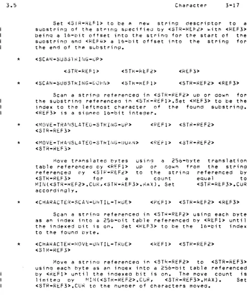
Set <SIR-REF1> to be ~ new string descriPtor to a suostring of the st~'ng specifie~ by <STR-HE~2> ~ith <REF3> being a 16-bit offset into the string for the start of the sUDstring and <REF4> a lb-bit offset into the string for the end of the substring.
*
<SCAN-SUB51RI~G-0P>*
*
*
*
<3TR-REF1> <STk-REF2> <RF..F3>
<SCAN-SUBSTkING-GO~N> <STk-KEF1> <STR-REF2> <REF3>
Scan a string referenced in <STR-REF2> UP or down for the substring referenceo in <STK-R£Fl>.Set <REF3> to be the
index to tr,e leftmost character of the found substring. <REF3> ;s a siRnea lb-bit integer.
<MOVE-TRA~SLATEP-STRING-UP>
<STR-REF3>
<~JjO VE" T H A I\)SLA TE O-S Tk I fllG"'DU 'I. N>
<STR-REF:»
<REF1> <STR-REF2>
<REF1> <STR-REF2>
Move translated bytes using a 256-byte translation table referenced Dy <REF1> UP or oown from the string
referenced by <STR-REFi> to the string referenced by
<STH-REF3> for a count equal to
MIN«STR-~EF2>.CUR,<STR-~EF3>.MAX). Set <STR-REF3>.CUR
accordingly.
<CHARACTER-SCAN-UNTIL-TkUE> <RtF1> <STR-REf2> <REF3>
Scan a strinq referencea in <ST~-REF2> using each byte as an index into a 256-bit table referenced by <REF1> until the indexed bit is on. Set <H£F3> to be the 16-bit index to the found byte.
<CHARACTER-MOV~-UNTIL-TRUE> <SlR-REF3>
<REFI> <STR-REF2>
Move a string referencea in <STR-REF2> to cSTR-REF3> usinq each byte as an inoex into a 256-oit table referenced by <~EF1> until the inaexea bit ;s on. The move count ;s limitec oy MIN«STR-REF2>.CUR, <STR-REF3>.MAX). Set
<STR-REF3>.CUR to the number of Characters movea.
Data General Corporation Company Confidential
[image:39.615.68.568.55.662.2]