Christopher A. Kent
December, 1987
degree of Doctor of Philosophy.
Partial support for this research was provided by NSF Grant DCR-8219178, and grants from Sun Microsystems and Digital Equipment Corporation.
This report was set in Times and Helvetica by the author using Scribe. The figures were produced using Adobe Illustrator and software of the author’s design.
Times is a trademark and Helvetica is a registered trademark of Allied Corporation. Illustrator is a trademark of Adobe Systems, Inc.
Scribe and UNILOGICare registered trademarks of Unilogic, Ltd.
UNIXis a trademark of Bell Laboratories.
VAXis a trademark of Digital Equipment Corporation.
Abstract
Caching has long been recognized as a powerful performance enhancement technique in many areas of computer design. Most modern computer systems include a hardware cache between the processor and main memory, and many operating systems include a software cache between the file system routines and the disk hardware.
In a distributed file system, where the file systems of several client machines are separated from the server backing store by a communications network, it is desirable to have a cache of recently used file blocks at the client, to avoid some of the communications overhead. In this configuration, special care must be taken to maintain consistency between the client caches, as some disk blocks may be in use by more than one client. For this reason, most current distributed file systems do not provide a cache at the client machine. Those systems that do place restric-tions on the types of file blocks that may be shared, or require extra communication to confirm that a cached block is still valid each time the block is to be used.
1. Introduction
The principle of locality of reference [41, 42] is the observation that computer programs ex-hibit both spatial and temporal locality in referencing objects (such as memory words or disk blocks). Temporal locality means that objects to be referenced in the near future are likely to have been in use recently. Spatial locality means there is a high probability that objects needed in the near future can be located near the objects currently in use. Less expensive access to recently used objects increases program performance.
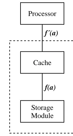
A cache is a device that exploits both spatial and temporal locality. It automatically maintains a copy of recently referenced objects in a higher-performance storage medium than that in which the objects themselves are stored. The program operates on copies that reside in the cache in-stead of operating directly on the objects, with a resultant increase in performance. The cache is responsible for propagating changes to the copies back to the stored objects. Figure 1-1 shows the difference between systems with and without a cache. The function f(a) describes the cost of accessing an object in the storage module. The function f′(a) describes the cost of accessing an object in the storage system that combines the storage module and the cache. Exploiting locality of reference allows the values of f′(a) to be less than f(a), for most a.
Processor
Module Storage
Processor
Module Storage Cache
f(a)
[image:6.612.353.474.468.693.2]f(a) f´(a)
A cache system is coherent if, whenever an object is read, the returned value is the one most recently written. A system with only one cache is coherent because there is only one path to and from the objects ---- through the single cache. In a system with N processing elements, N>1, sharing a common pool of objects, there are N paths to and from the objects. If each path con-tains a cache holding copies of some of the objects, copies of the same objects can exist in more than one cache. A mechanism to propagate updates from one cache to another is necessary to insure coherence.
Several cache coherence mechanisms exist for systems of processors and caches that share a common block of main memory. The machines operate in an environment where systems are tightly coupled, highly synchronous, with reliable communication paths that are as fast as those in the memory subsystem.
It is increasingly common to connect processors in more loosely coupled systems. The only communication path between processors and the resources they share is a communications net-work [55] that has transmission speeds several orders of magnitude slower than main memory. We describe a mechanism for cache coherence in these systems.
1.1. Background
The idea that a computer should use a memory hierarchy dates back to at least the early por-tion of the 20th century; it is suggested in the pioneering paper of von Neumann et al. [59]. The motivation for a storage hierarchy in a processor is economic. The performance and cost of various storage technologies varies widely. Usually, the fastest and most expensive technology is used for the registers in the processor. Ideally, one would like to execute programs as if all data existed in the processor registers. When more data are required, larger, lower-cost storage tech-nologies are used for data and instruction storage, proceeding from fast semiconductor memory, to slower semiconductor memory, to magnetic disk storage, and finally to magnetic tape or other archival storage media.
Registers Cache Main Secondary Backing Archival Memories Memories ‘‘Core’’ Stores Stores
3 7 8
Access time 10 10 100 10 10 10
(ns)
3 4 5
Transfer time 10 10 100 10 10 10
(ns)
0 10 5 14 16 24 20 26 25 30 25 40
Addressable 2 -2 2 -2 2 -2 2 -2 2 -2 2 -2 units
Technology Semiconductor Semiconductor Semiconductor Semiconductor Magnetic Magnetic Optical
Table 1-1: Characteristics of various memory technologies
eliminating the bottleneck while retaining the advantages of the larger, slower memory. The ob-jects to be placed in the faster memory are selected to minimize the time the accessor spends waiting for objects to be copied back and forth. The overhead of the copying operations is offset by the performance advantage gained through repeated references to copies in the faster memory.
The process of selecting which objects to move between levels in the memory hierarchy was first automated in theATLAS demand paging supervisor [22, 31]. TheATLAS machine had two levels in its hierarchy − core memory and a drum. The demand paging supervisor moved memory between the core memory and the drum in fixed-sized groups called pages. An automatic system was built that allowed users to view the combination of the two storage sys-tems as a single level (i.e., the operation of the mechanism was transparent). This ‘‘one-level storage system’’ incorporated an automatic learning program that monitored the behavior of the main program and attempted to select the correct pages to move to and from the drum.
The ATLAS one-level store was the first example of virtual memory − a mechanism that ex-pands the space available for programs and data beyond the limits of physical main memory. In fact, this mechanism is simply an environment where programs and data are stored in their en-tirety outside of main memory, and main memory is a cache for the processor.
The IBM 360/85 [12] incorporated the first application of this idea to high speed devices. The term cache was introduced in [34] to describe the high speed associative buffer in the memory subsystem of the 360/85. This buffer was used to hold copies of recently referenced words from main memory.
So far, we have discussed caching only in the context of managing the memory space of a processor. Many other forms of caching exist. Caches of recently referenced disk blocks held in main memory increase overall disk system performance [58, 51]. Digital typesetters cache font information to reduce the amount of data transmitted over the communications channel from the host computer [23]. Program execution times can be enhanced by precomputing and caching values of expensive functions (e.g., trigonometric functions) and using table lookup rather than run-time computation. Applicative language systems cache the result values of expressions to avoid needless recomputation [30].
1.2. Caching in computer systems
1.2.1. Single cache systems
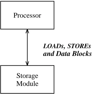
We now examine the most common type of cache in computer systems − that found in a uniprocessor system between the central processor unit (CPU) and main memory. For example, with a CPU cycle time of 60ns and memory access time of 150ns, there is a large disparity be-tween the relative speeds of the CPU’s need to access memory and the ability of the memory system to satisfy requests. In a configuration where theCPUdirectly accesses main memory, the
CPU will waste two to three cycles per memory reference, waiting for memory to respond. (See Figure 1-2.) Wiecek measured CPU instruction set usage in a time-sharing environment on a
per instruction is 1.18. McDaniel found similar results in his study of instruction set usage on a personal workstation in [35]. Thus, in our example, lack of a cache would cause the CPUto wait an average of 2.875 cycles for each memory reference, allowing an average 35% processor utilization.
Processor
Module Storage
LOADs, STOREs
[image:9.612.242.397.140.298.2]and Data Blocks
Figure 1-2: Uniprocessor without cache
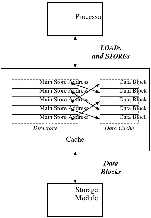
A cache is introduced as a small amount of high-speed memory between the CPU and memory. (See Figure 1-3.) The cache memory has an access time comparable to the cycle time of the CPU. The cache hardware contains control logic to manage a directory of the locations stored in the cache, as well as the additional memory for cached values. When theCPUperforms aLOADfrom memory, the cache first searches its directory for a copy of the desired location. If found, the cache returns a copy of the contents. If the location is not cached, theCPUwaits while the cache fetches the location from slower main memory, copies the value into the cache, and returns it to theCPU. In practice, the cache manipulates blocks of memory consisting of several contiguous words, to reduce directory overhead. When the contents of a particular memory word must be copied into the cache, the entire surrounding block is copied into memory.
The amount of storage in a cache is finite. If no free space remains in the cache to hold the contents of the block just fetched, one of the currently held locations must be selected for removal. Most systems remove the least recently used object under the assumption that the entries in the cache not used for the longest period are the least likely to be re-used in the near future.
When the CPUexecutes a STORE to memory, the cache checks its directory for a copy of the referenced location. If found, the cache updates the copy, and does not write to main memory. The cache writes the update to main memory when the block containing the location is selected for removal from the cache. This minimizes the average access delays on aSTORE. A cache that uses this method of propagating updates is called a write-back cache.
Module Storage Main Store Address Main Store Address Main Store Address Main Store Address Main Store Address
Directory
Data Block Data Block Data Block Data Block Data Block
Data Cache
Cache Processor
and STOREs
LOADs
[image:10.612.201.448.68.425.2]Blocks Data
Figure 1-3: Uniprocessor with cache/directory
In a disk block cache, the file system portion of the operating system maintains copies of recently accessed disk blocks. All disk operations search the disk cache for the desired block before accessing the disk, yielding greatly improved disk subsystem performance.
1.2.2. Multiple cache systems
In a tightly coupled multiprocessor, N CPUs share the same main storage. If each CPU has a private cache, there are now multiple access paths to main memory, and care must be taken to preserve coherence.
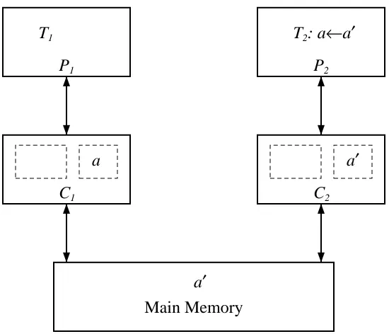
Let us examine a specific example consisting of two tasks, T and T , running on processors1 2
P and P with caches C and C (see Figure 1-4). Let a be the address of a main memory1 2 1 2
location that is referenced and modified by both tasks. A modification of a by T is completed in1
C but not returned to main memory. Thus, a subsequent1 LOAD by T will return an obsolete2 value of a.
Even a write-through cache does not insure coherence. After both T and T have referenced1 2
a, subsequent references will be satisfied by the cache, so a new value written to main memory
Main Memory
a′ C1
a
C2
a′ P1
T1
P2
[image:11.612.151.426.72.308.2]T2: a←a′
Figure 1-4: Two competing caches after T modifies a2
Sharing a single cache between the N processors eliminates coherence problems. But such a cache is likely to be a performance bottleneck. The demands on it would be N times that of a single cache, because it would handle all the data requests for each of the N processors. Also, with all the processors sharing a single cache, much of the history of reference for each processor will be lost, and with it, much of the performance advantage.
A mechanism is necessary to couple the caches and actively manage their contents. Several such mechanisms have been devised, relying on the removal of memory blocks from caches whenever there is a risk that their contents may have been modified elsewhere in the system. Inappropriate (too frequent) removal will result in greatly decreased performance, because more time will be spent waiting for blocks to be loaded into the cache.
1.2.2.1. Tang’s solution
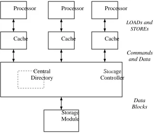
Tang presented the first practical design for a multicache, multiprocessor system [56]. The cache structure for each processor is the same as in a single cache system, with some additional features to facilitate communication among caches.
Tang makes a distinction between cache entries that are private and shared. An entry is private if it has been modified with respect to main memory, or is about to be modified by the corresponding processor. A private entry can exist in only one cache so that, at any instant, there is only one version of the data in the system.
A shared entry has not been modified by any processor. It is allowed to exist simultaneously in several caches in the system, to allow ‘read only’ data to be accessed more efficiently.
the cache controller alters the cache directory to show that a copy of the fetched memory loca-tion is present in the cache. The storage controller also alters the central directory to show that a copy of the memory location is in the cache.
Module Storage
Controller Storage Directory
Central
Cache Cache Cache
Processor Processor Processor
Blocks Data and Data Commands
[image:12.612.179.498.118.398.2]STOREs LOADs and
Figure 1-5: Tang’s multiprocessor
The normal LOAD and STORE instructions between the processor and the caches are aug-mented with new commands sent from the caches to the storage controller and from the con-troller to the caches. Using these commands, the storage concon-troller ensures that the cache system remains coherent. The controller converts shared blocks to private blocks when a processor is about to write a location, then converts private blocks to shared blocks when another processor attempts to read a location previously marked as private.
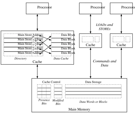
1.2.2.2. The Presence Bit solution
The Presence Bit solution for multicache coherence [44] is similar to Tang’s solution. Instead of duplicating each cache’s directory in a central directory, main memory has N+1 extra bits per block. N of these bits correspond to the caches in the system, and are set if and only if the cor-responding cache has a copy of the block. The remaining bit is reset if and only if the contents of the main memory block are identical to all cached copies. Each cache has, associated with each block, a bit that is set to show that this cache has the only copy of this block.
Processor Processor Processor
Cache Cache
Main Memory
Cache Control Data Storage
Bits Presence
Bits
Modified Data Words or Blocks
Cache Main Store Address Main Store Address Main Store Address Main Store Address Main Store Address
[image:13.612.78.512.72.435.2]P r i v a t e B i t s Directory Data Block Data Block Data Block Data Block Data Block Data Cache STOREs LOADs and Data Commands and
Figure 1-6: Presence Bit solution
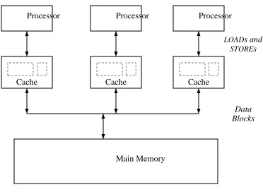
1.2.2.3. The Snoopy or Two-Way cache
A snoopy cache is one that watches all transactions between processors and main memory and can manipulate the contents of the cache based on these transactions.
Three kinds of snoopy cache mechanisms have been proposed. A write-through strategy [2] writes all cache updates through to the main memory. Caches of the other processors monitor these updates, and remove held copies of memory blocks that have been updated.
A second strategy is called write-first [24]. On the firstSTOREto a cached block, the update is written through to main memory. The write forces other caches to remove any matching copies, thus guaranteeing that the writing processor holds the only cached copy. SubsequentSTOREs can be performed in the cache. A processor LOAD will be serviced either by the memory or by a cache, whichever has the most up-to-date version of the block.
The third strategy is called ownership. This strategy is used in the SYNAPSE
Main Memory
Blocks Data
Cache Cache Cache
STOREs LOADs and
[image:14.612.160.532.64.336.2]Processor Processor Processor
Figure 1-7: Snoopy Cache organization
main memory. When a cache needs to fetch a block, it issues a public read, to which the owner of the block responds by returning a current copy. Ownership of the block does not change.
When a processor P desires to modify a block, ownership of the block is transferred from the current owner (either main memory or another cache) to P’s cache. This further reduces the number of STOREs to main memory. All other caches having a copy of this block notice the change in ownership and remove their copy. The next reference causes the new contents of the block to be transferred from the new owner. Ownership of a block is returned to main memory when a cache removes the block in order to make room for a newly accessed block.
A snoopy cache has the smallest bit overhead of the discussed solutions, but the communica-tion path must be fast and readily accessible by all potential owners of memory blocks. Opera-tions between owners are tightly synchronized. The other soluOpera-tions allow the caches and memory to be more loosely coupled, but rely on a central controller for key data and arbitration of com-mands.
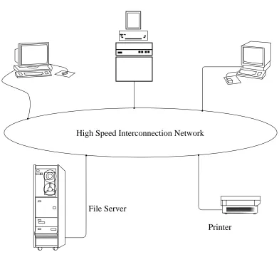
1.3. Distributed Cache Systems
Management of shared resources is typically provided by a trusted central authority. The workstations, being controlled by their users, cannot be guaranteed to be always available or be fully trusted. The solution is to use server machines to administer the shared resources. A file
server is such a machine that makes available a large quantity of disk storage to the client
workstations. The clients have little, if any, local disk storage, relying on the server for all long-term storage.
High Speed Interconnection Network
File Server
[image:15.612.94.486.173.534.2]Printer Workstations
Figure 1-8: Typical distributed system
The disparity in speeds between processor and remote disk make an effective caching scheme desirable. However, no efficient, fully transparent solutions exist for coherence in a distributed system. Distributed data base systems [13] use locking protocols to provide coherent sharing of objects between clients on a network. These mechanisms are incorporated into the systems at a very high level, built on a non-transparent network access mechanism, and are not concerned with performance improvements. We prefer a solution that is integral to the network file system, and provides the extra performance of an embedded cache.
1.3.1. Sun Microsystems’ Network Disk
Sun Microsystems’ Network Disk [48] is an example of the simplest form of sharing a disk across the network. The client workstation contains software that simulates a locally attached disk by building and transmitting command packets to the disk server. The server responds by transferring complete disk blocks. The client has a disk block caching system, keeping the most recently used blocks in main memory. The server’s disk is partitioned into as many logical disks as there are clients. No provision is made for communication among clients’ caches; clients can only share read-only data.
1.3.2. CFS
The Cedar experimental programming environment [8] developed at the Xerox Palo Alto Research Center supports a distributed file system called CFS [9]. Each of the Cedar worksta-tions has a local disk, and this disk can be used for local private files or shared files copied from a remote file server.
A file to be shared is first created as a file on the local disk. To make the file available for sharing, the client transfers it to the remote file server. A client on another workstation can then share the file by copying it to his local disk. The portion of the disk not occupied by local files is used as a cache for remote files. Files are transferred between client and server as a whole.
Coherence of the cache of files on local disk is guaranteed because shared files may not be modified. To update the contents of a shared file, a new version which reflects the updated infor-mation is created on the server. This version has the same name as the original file upon which it is based; only the version numbers differ. Thus, all cached copies of a particular version of a file contain the same data. It is possible, however, to have a cached copy of a file that does not reflect the latest version of the file.
1.3.3. The ITC Distributed File System
The Information Technology Center of Carnegie-Mellon University is building a campus-wide distributed system. Vice, the shared component of the distributed system, implements a dis-tributed file system that allows sharing of files [28]. Each client workstation has a local disk, which is used for private files or shared files from a Vice file server. Shared files are copied as a whole to the local disk upon open, and the client operating system uses this local copy as a cache to satisfy disk requests. In this regard, the ITC caching mechanism is similar to that of CFS.
Cache validation is currently performed by the client querying the server before each use of the cached copy. A future implementation will allow the server to invalidate the client’s cached copy. Changes in the cached copy are stored back to the server when the file is closed.
1.3.4. Sun Microsystems Network File System
Changed blocks are written back to the server on file close. At that time, all blocks associated with the file are flushed from the cache. Each entry in the cache has an associated timeout; when the timeout expires, the entry is automatically removed from the cache. Cached files also have an associated timestamp. With each read from a remote file, the server returns the timestamp infor-mation for that file. The client compares the current timestamp inforinfor-mation with the inforinfor-mation previously held. If the two differ, all blocks associated with the file are flushed from the cache and fetched again.
Coherence between client caches is achieved by ensuring that each client is coherent with the server’s cache. However, because the changes made by a client are not seen until the client closes the file, there can be periods of time when two clients caching the same file have different values for the same cached block.
1.3.5. Apollo DOMAIN
The Apollo DOMAIN operating system embodies a distributed file system that allows loca-tion transparent access of objects [16]. Each workstaloca-tion acts as a client, and may act as a server if it has local disk storage. Main memory is used as a cache for local and remote objects in the file system.
The distributed file system does nothing to guarantee cache coherence between nodes. Client programs are required to use locking primitives provided by the operating system to maintain consistency of access. The designers decided that providing an automatic coherence mechanism in the cache system was counter to their efficiency goals.
1.4. Memory systems vs. Distributed systems
Let us return to the memory subsystem solutions and examine the fundamental assumptions that render them inappropriate for a distributed system environment. All the solutions require reliable communications between the various components of the memory hierarchy. In addition, the snoopy cache requires not only direct communications, but reliable receipt of broadcast mes-sages. Reliable communication is achieved by building synchronous systems that allocate some portion of the cycle time to doing nothing but receiving messages.
Because electrical disturbances may occur on local area networks, it is not possible to achieve reliable communications without considerable overhead. Reliable stream-oriented protocols like TCP [57] are required for point-to-point connections. A broadcast network such as the Ethernet [61], on which hosts have the ability to receive all transmissions on the medium (i.e., hosts can be promiscuous), would seem ideal for a snoopy cache implementation. However, the Ethernet provides only ‘‘best effort’’ delivery. To provide reliable broadcast communications, a specialized protocol must be employed [10, 43], with much overhead. Even if cheap reliable broadcast were available, processing every message on the network imposes a high load on sys-tems.
In a distributed system, in the time that it takes processor P to send a message indicating aA desire for a private read or an update, processor P may be updating its shared copy of that sameB block (which should actually now be private to P and have been removed from P ’s cache).A B Because a distributed system is asynchronous, access to shared blocks must be serialized by ex-plicit locking mechanisms. These mechanisms involve sending messages between clients and servers and encounter large communication delays. Because the communications delays are large, the size of the blocks that are locked are large, to maximize the ratio of available data to locking overhead. Unlike a memory system, locks are held for a long time (relative to processor cycle time), and a processor may have to stall for a long time waiting for a shared block.
1.5. Our Solution: The Caching Ring
We propose a network environment that provides transparent caching of file blocks in a dis-tributed system. The user is not required to do any explicit locking, as in traditional database concurrency control algorithms, nor is there any restriction on the types of files that can be shared.
The design is inspired by both the snoopy memory cache and the Presence Bit multicache coherence solution. Caches that hold copies of a shared file object monitor all communications involving that object. The file server maintains a list of which caches have copies of every object that is being shared in the system, and issues commands to maintain coherence among the caches.
Our environment retains many of the benefits of cost local area networks. It uses a low-cost communications medium and is easily expandable. However, it allows us to create a more efficient mechanism for reliable broadcast or multicast than is available using ‘‘conventional’’ methods previously mentioned. Operation of the caches relies on an intelligent network interface that is an integral part of the caching system.
The network topology is a ring, using a token-passing access control strategy [19, 18, 45]. This provides a synchronous, reliable broadcast medium not normally found in networks such as the Ethernet.
1.5.1. Broadcasts, Multicasts, and Promiscuity
Because it is undesirable to burden hosts with messages that do not concern them, a multicast addressing mechanism is provided. Most multicast systems involve the dynamic assignment of arbitrary multicast identifiers to groups of destination machines (stations) by some form of centralized management. Each station must use a costly lookup mechanism to track the current set of identifiers involving the station. On every packet receipt, the station must invoke this lookup mechanism to determine if the packet should be copied from the network to the host.
n
is possible to efficiently manage 2 multicast groups with reliable one ring cycle delay delivery, as opposed to n point-to-point messages for a multicast group of size n, which is typical for reliable multicast protocols on the Ethernet.
Missed packets are a rare problem, because the token management scheme controls when packets can arrive, and the interface hardware and software is designed to be always ready to accept the next possible packet, given the design parameters of the ring. The primary reasons for missed packets are that stations crash or are powered down, or packets that are damaged due to ring disturbances.
1.5.2. Ring Organization
Traffic on the ring consists of two types of packets: command and data. Each station intro-duces a fixed delay of several bit times to operate on the contents of a packet as it passes by, possibly recording results in the packet as it leaves. Command packets and their associated operations are formulated to keep delays at each station to a minimum constant time. If, for example, the appropriate response is to fetch a block of data from a backing store, the command packet is released immediately, and the block is then fetched and forwarded in a separate data packet.
The interface contains the names of the objects cached locally, while the objects themselves are stored in memory shared between the interface and the host. Thus, status queries and com-mands are quickly executed.
1.6. Previous cache performance studies
Many of the memory cache designs previously mentioned are paper designs and were never built. Of the ones that were built, only a few have been evaluated and reported on.
Bell et al. investigated the various cache organizations using simulation during the design process of a minicomputer [5]. Their results were the first comprehensive comparison of speed
vs. cache size, write-through vs. write-back, and cache line size, and provided the basis for much
of the ‘‘common knowledge’’ about caches that exists today.
Smith has performed a more modern and more comprehensive survey of cache organizations in [50]. This exhaustive simulation study compares the performance of various cache organiza-tions on program traces from both the IBM System/360 and PDP-11 processor families.
1.7. Previous file system performance studies
There has been very little experimental data published on file system usage or performance. This may be due to the difficulty of obtaining trace data, and the large amounts of trace data that is likely to result. The published studies tend to deal with older operating systems, and may not be applicable in planning future systems.
Smith studied the file access behavior of IBM mainframes to predict the effects of automatic file migration [52]. He considered only those files used by a particular interactive editor, which were mostly program files. The data were gathered as a series of daily scans of the disk, so they do not include files whose lifetimes were less than a day, nor do they include information about the reference patterns of the data within the files. Stritter performed a similar study covering all files on a large IBM system, scanning the files once a day to determine whether or not a given file had been accessed [53]. Satyanarayanan analyzed file sizes and lifetimes on a PDP-10 sys-tem [46], but the study was made statically by scanning the contents of disk storage at a fixed point in time. More recently, Smith used trace data from IBM mainframes to predict the perfor-mance of disk caches [51].
Four recent studies contain UNIX measurements that partially overlap ours: Lazowska et al. analyzed block size tradeoffs in remote file systems, and reported on the disk I/O required per user [32], McKusick et al. reported on the effectiveness of current UNIX disk caches [36], and Ousterhout et al. analyzed cache organizations and reference patterns in UNIX systems [38]. Floyd has reported extensively on short-term user file reference patterns in a university research environment [21]. We compare our results and theirs in Section 3.6.
1.8. Plan of the thesis
After defining the terminology used in the rest of the work, we examine the use and perfor-mance of a file system cache in a uniprocessor, first with local disks and then with remote disks. We then proceed to investigate applications of the caching ring to a multipleCPU, multiple cache system under similar loads.
2. Definitions and Terminology
As mentioned in Chapter 1, we are concerned with caching in distributed systems, and in par-ticular, in file systems. In this chapter, we define the fundamental components of distributed systems, file systems, and cache systems, as well as a notation for discussing cache operations. Since much of our work is centered around the UNIX file system, we briefly introduce some details of that implementation.
2.1. Fundamental components of a distributed system
Physically, a distributed system consists of a set of processors, with a collection of local
storage mechanisms associated with each processor. A processor is able to execute programs that
access and manipulate the local storage, where the term process denotes the locus of control of an executing program [17]. In addition, an interconnection network connects the processors and allows them to communicate and share data via exchange of messages [55]. These messages are encapsulated inside packets when transmitted on the network.
2.1.1. Objects
We conceptually view the underlying distributed system in terms of an object model [29] in which the system is said to consist of a collection of objects. An object is either a physical resource (e.g., a disk or processor), or an abstract resource (e.g., a file or process). Objects are further characterized as being either passive or active, where passive objects correspond to stored data, and active objects correspond to processes that act on passive resources. For the purposes of this thesis, we use the term object to denote only passive objects.
The objects in a distributed system are partitioned into types. Associated with each object type is a manager that implements the object type and presents clients throughout the distributed sys-tem with an interface to the objects. The interface is defined by the set of operations that can be applied to the object.
An object is identified with a name, where a name is a string composed of a set of symbols chosen from a finite alphabet. For this thesis, all objects are identified by simple names, as defined by Comer and Peterson in [39]. Each object manager provides a name resolution
mechanism that translates the name specified by the client into a name that the manager is able to resolve and use to access the appropriate object. Because there is a different object manager for
An object manager can treat a name as a simple or compound name. A compound name is composed of one or more simple names separated by special delimiter characters. For example, an object manager implementing words of shared memory might directly map the name provided by the client into a hardware memory address. This is known as a flat namespace. On the other hand, an object manager implementing a hierarchical namespace in which objects are grouped together into directories of objects, provides a mechanism for adding structure to a collection of objects. Each directory is a mapping of simple names to other objects. During the evaluation of a name, a hierarchical evaluation scheme maintains a current evaluation directory out of the set of directories managed by the naming system. Each step of hierarchical name evaluation includes the following three steps:
1. Isolate the next simple name from the name being evaluated.
2. Determine the object associated with the simple name in the current evaluation directory.
3. (If there are more name components to evaluate) Set the current evaluation direc-tory to the direcdirec-tory identified in Step 2, and return to Step 1.
2.1.2. Clients, managers, and servers
Clients and managers that invoke and implement operations are physically implemented in terms of a set of cooperating processes. Thus, they can be described by the model of distributed processing and concurrent programming of remote procedure calls [37].
In particular, we divide processors into two classes: client machines that contain client programs, and server machines that contain object manager programs. Each server has one or more attached storage devices, which it uses as a repository for the data in the objects imple-mented by the object managers. In our system, there are N client machines, denoted C . . . C ,1 N and one server machine, denoted S.
2.2. Caches
Caches are storage devices used in computer systems to temporarily hold those portions of the
contents of an object repository that are (believed to be) currently in use. In general, we adhere to the terminology used in [50], with extensions from main memory caching to caching of general-ized objects. A cache is optimgeneral-ized to minimize the miss ratio, which is the probability of not finding the target of an object reference in the cache.
The cache has three components: a collection of fixed-sized blocks of object storage (also known in the literature as lines); the cache directory, a list of which blocks currently reside in the cache, showing where each block is located in the cache; and the cache controller, which imple-ments the various algorithms that characterize the operation of the cache.
Information is moved between the cache and object repository one block at a time. The fetch
algorithm determines when an object is moved from the object repository to the cache memory.
When information is fetched from the object repository, if the cache is full, some information in the cache must be selected for replacement. The replacement algorithm determines which block is removed. Various replacement algorithms are possible, such as first in, first out (FIFO), least recently used (LRU), and random.
When an object in the cache is updated, that update can be reflected in one of several ways. The update algorithm determines the mechanism used. For example, a write-back algorithm has the cache receive the update and update the object repository only when the modified block is replaced. A write-through algorithm updates the object repository immediately.
2.3. Files and file systems
A file is an object used for long-term data storage. Its value persists longer than the processes that create and use it. Files are maintained on secondary storage devices like disks. Conceptually, a file consists of a sequence of data objects, such as integers. To provide the greatest utility, we consider each object in a file to be a single byte. Any further structure must be enforced by the programs using the file.
The file system is the software that manages these permanent data objects. The file system provides operations that will create or delete a file, open a file given its name, read the next object from an open file, write an object onto an open file, or close a file. If the file system allows random access to the contents of the file, it may also provide a way to seek to a specified location in a file. Two or more processes can share a file by having it open at the same time. Depending on the file manager, one or more of these processes may be allowed to write the shared file, while the rest may only read from it.
2.3.1. File system components
The file system software is composed of five different managers, each of which is used to implement some portion of the file system primitives.
The access control manager maintains access lists that define which users may access a par-ticular file, and in what way−whether to read, write, delete, or execute.
The directory manager implements the naming directories used to implement the name space provided by the file system. It provides primitives to create and delete entries in the directories, as well as to search through the existing entries.
The naming manager implements the name space provided by the file system. The name evaluation mechanism is part of the naming manager, and uses the directory manager primitives to translate file names into object references.
The file manager interacts with the disk manager to map logical file bytes onto physical disk blocks. The disk manager manipulates the storage devices, and provides primitives to read or write a single, randomly accessed disk block. The disk manager may implement a cache of recently referenced disk blocks. Such a cache is called a disk block cache.
blocks can be larger or smaller than the hardware block size of the disk on which they reside. The file manager may implement a file block cache of recently referenced logical file blocks.
The file manager maintains several files which are private to its implementation. One contains the correspondence of logical file blocks to physical disk blocks for every file on the disk. Another is a list of the physical disk blocks that are currently part of a file, and the disk blocks that are free. These files are manipulated in response to file manager primitives which create or destroy files or extend existing ones.
In a distributed file system implementation, where the disk used for storage is attached to a server processor connected to the client only by a network, we distinguish between disk servers and file servers. In a disk server, the disk manager resides on the server processor, and all other file system components reside on the client. A disk server merely provides raw disk blocks to the client processor, and the managers must retrieve all mapping and access control information across the network.
In a file server, all five managers are implemented on the server processor. Client programs send short network messages to the server, and receive only the requested information in return messages. All access control computations, name translations, and file layout mappings are per-formed on the server processor, without requiring any network traffic.
2.3.2. TheUNIXfile system
The UNIXfile system follows this model, with some implementation differences [6]. The ac-cess control lists are maintained in the same private file as the mappings between logical file blocks and physical disk blocks. Together, the entries in this file are known as inodes.
The UNIXfile name resolution mechanism implements a hierarchical naming system. Direc-tories appear as normal files, and are generally readable. User programs may read and interpret directly, or use system-provided primitives to treat the directories as a sequence of name objects. Special privileges are required to write a directory, to avoid corruption by an incorrectly imple-mented user program.
In UNIX, file names are composed of simple names separated by the delimiter character ‘/’. Names are evaluated, as outlined in the hierarchical name evaluation given above, with the cur-rent evaluation directory at each step being a directory in the naming hierarchy. Names are finally translated into unique, numerical object indices. The object indices are then used as file identifiers by the file manager. The namespace of the UNIXnaming mechanism can also be thought of as a tree-structured graph.
To improved file system performance, the disk manager implements a disk block cache. Blocks in this cache are replaced according to a least recently used replacement policy [58].
2.3.3. Our view of file systems
strings used in a hierarchical naming system to the numerical object identifiers used thereafter to refer to file objects is not part of the caching mechanism.
3. Analysis of a Single-Processor System
There has been very little empirical data published on file system usage or performance. Ob-taining trace data is difficult, typically requiring careful modifications to the operating system, and the resulting data is voluminous. The published studies tend to deal with older operating systems, and for this reason may not be applicable in planning future systems.
This chapter extends our understanding of caching to disk block caches in single processor systems. We recorded the file system activity of a single processor timesharing system. We analyzed this activity trace to measure the performance of the disk block cache, and performed simulation experiments to determine the effects of altering the various parameters of the processor’s disk block cache. We also measured the amount of shared file access that is actually encountered. These measurements and simulation experiments allow us to characterize the demands of a typical user of the file system, and the performance of the file system for a given set of design parameters.
3.1. Introduction
Understanding the behavior of file block caching in a single processor system is fundamental to designing a distributed file block caching system and analyzing the performance of that cach-ing system. Uscach-ing an accurate model of the activity of a scach-ingle user on a client workstation, we can build simulations of a collection of such workstations using a distributed file block caching system. By analyzing the file activity on a single-processor system, we can develop such a model. To this end, we designed experiments to collect enough information about an existing system to allow us to answer questions such as:
•How much network bandwidth is needed to support a workstation?
•How much sharing of files between workstations should be expected?
•How should disk block caches be organized and managed?
•How much performance enhancement does a disk block cache provide?
The experiments are an independent effort to corroborate similar data reported by McKusick [36], Lazowska et al. [32], and Ousterhout et al. [38], in a different environment, and with a different user community and workload. We compare our results and theirs in Section 3.6.
and write requests, along with the time of access. The amount of information is voluminous, but allows us to perform a detailed analysis of the behavior and performance of the file and disk subsystems.
We wrote several programs to process the trace files− an analysis program that extracts data regarding cache effectiveness and file system activity, a data compression program, and a block cache simulator. Using these programs, we were able to characterize the file system activities of a single client, and the performance benefits of a disk block cache in various configurations.
3.2. Gathering the data
Our main concerns in gathering the data were the volume of the data and affecting the results by logging them through the cache system under measurement. We wished to gather data over several days to prevent temporary anomalies from biasing the data. We also wished to record all file system activity, with enough information to accurately reconstruct the activity in a later simulation. It quickly became obvious that it would not be feasible to log this data to disk − an hour of typical disk activity generates approximately 8.6 Mbytes of data.
The method settled upon used the local area network to send the trace data to another system, where it was written to magnetic tape. Logging routines inserted into the file system code placed the trace records in a memory buffer. A daemon read the records from the trace buffer and sent them to a logging process via aTCPconnection. The logger simply wrote the records on tape. A day’s activity fills a 2400 foot tape recorded at 6250 bpi.
In this manner, the buffers used in the disk subsystem are completely bypassed. The daemon that reads and sends trace records consumed approximately 3% of the CPU, and the impact on the performance of the disk subsystem is negligible.
3.3. The gathered data
We inserted probes to record activity in both the file manager and the disk manager. All event records are marked with the time at which they occurred, to millisecond resolution.
In the file manager, we recorded all file open, close, read, and write events. Each event record contains the name of the process and user that requested the action. Open events record the file index that uniquely identifies the file on disk, and the inode information, but not the name by which the user called it. Close event records contain the same data. Read and write event records identify the affected file, the point in the file at which the transfer began, and how many bytes were transferred.
In the disk manager, operations are performed on physical blocks. Only read and write events occur at this level. Each event record contains the address of the first block used in the transfer, how many bytes were transferred, and whether or not the block(s) were found in the disk block cache.
transferring inodes between disk and memory. Also, paging operations do not use the disk block cache, and are not recorded in this trace. When a new program is invoked (via the exec system call), the first few pages of the program are read through the disk block cache, and are recorded in our trace data. The remaining pages are read on demand as a result of page faults, and this activity does not appear in our trace data. We can estimate the overhead involved in file name lookup by comparing the disk activity recorded in our traces and the simulated disk activity in our simulations.
3.3.1. Machine environment
We collected our trace data on a timeshared Digital Equipment Corporation VAX-11/780 in the Department of Computer Sciences at Purdue University. The machine is known as ‘‘Merlin’’ and is used by members of theTILDEproject for program development and document editing, as well as day-to-day housekeeping. Merlin has 4 Mbytes of primary memory, 576 Mbytes of disk, and runs the 4.2BSD version of the UNIX operating system. The disk block cache is ap-proximately 400 Kbytes in size.
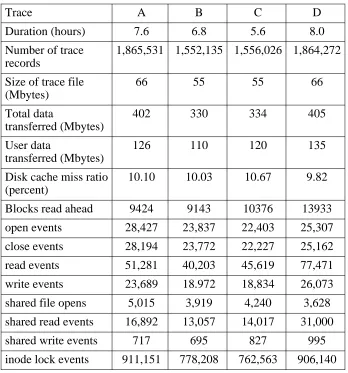
Traces were collected for four days over the period of a week. We gathered data during the hours when most of our users work, and specifically excluded the period of the day when large system accounting procedures are run. Trace results are summarized in Table 3-1, where each individual trace is given an identifying letter. During the peak hours of the day, 24 − 34 files were opened per second, on average. TheUNIX load average was typically 2 − 8, with under a dozen active users.
3.4. Measured results
Our trace analysis was divided into two parts. The first part contains measurement of current
UNIX file system activity. We were interested in two general areas: how much file system ac-tivity is generated by processes and system overhead, and how often files are shared between processes, and whether processes that share files only read the data or update the data as well. The second part of our analysis, examining the effectiveness of various disk cache organizations, is presented in Section 3.5.
3.4.1. System activity
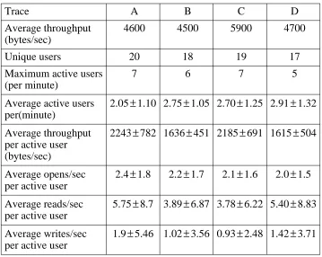
The first set of measurements concerns overall file system activity in terms of users, active files, and bytes transferred (see Table 3-2). The most interesting result is the throughput per ac-tive user. We consider a user to be acac-tive if he or she has any file system activity within a one-minute interval. Averaged over a one-one-minute interval, active users tend to transfer only a few kilobytes of data per second. If only one-second intervals are considered, users active in these intervals tend to transfer much more data per second (approximately 10 Kbytes per second per active user), but there are fewer active users.
Trace A B C D
Duration (hours) 7.6 6.8 5.6 8.0
Number of trace 1,865,531 1,552,135 1,556,026 1,864,272 records
Size of trace file 66 55 55 66
(Mbytes)
Total data 402 330 334 405
transferred (Mbytes)
User data 126 110 120 135
transferred (Mbytes)
Disk cache miss ratio 10.10 10.03 10.67 9.82 (percent)
Blocks read ahead 9424 9143 10376 13933
open events 28,427 23,837 22,403 25,307
close events 28,194 23,772 22,227 25,162
read events 51,281 40,203 45,619 77,471
write events 23,689 18.972 18,834 26,073
shared file opens 5,015 3,919 4,240 3,628
shared read events 16,892 13,057 14,017 31,000
shared write events 717 695 827 995
[image:31.612.115.463.68.441.2]inode lock events 911,151 778,208 762,563 906,140
Table 3-1: Description of activity traces
reading and writing inodes from disk. They also define a user as one who is active over a ten minute interval, and the throughput figure is averaged over that time period.
Trace A B C D
Average throughput 4600 4500 5900 4700 (bytes/sec)
Unique users 20 18 19 17
Maximum active users 7 6 7 5
(per minute)
Average active users 2.05±1.10 2.75±1.05 2.70±1.25 2.91±1.32 per(minute)
Average throughput 2243±782 1636±451 2185±691 1615±504 per active user
(bytes/sec)
Average opens/sec 2.4±1.8 2.2±1.7 2.1±1.6 2.0±1.5 per active user
Average reads/sec 5.75±8.7 3.89±6.87 3.78±6.22 5.40±8.83 per active user
[image:32.612.145.504.68.354.2]Average writes/sec 1.9±5.46 1.02±3.56 0.93±2.48 1.42±3.71 per active user
Table 3-2: Measurements of file system activity
However, the low average throughput per active user suggests that a single 10Mbit/second network has enough bandwidth to support several hundred users using a network-based file sys-tem. Transfer rates tended to be bursty in our measurements, with rates as high as 140 Kbytes/sec recorded for some users in some intervals, but such a network could support several such bursts simultaneously without difficulty.
We performed simple analysis of access patterns to determine the percentage of files that are simply read or written straight through, with no intermediate seeks. Table 3-3 summarizes our results. The percentages are cumulative, i.e., 80.2% of the file accesses in trace A had two or fewer seeks. These measurements confirm that file access is highly sequential. Ousterhout et al. report that more than 90% of all files are processed sequentially in their computing environment.
Trace A B C D
Linear access 17634 (62.5%) 15118 (63.6%) 13776 (62.0%) 16683 (66.3%)
One seek 4889 (79.2%) 4119 (80.9%) 3561 (78.0%) 3952 (82.0%)
Two seeks 272 (80.2%) 265 (82.0%) 253 (79.1%) 271 (83.1%)
Three or more 5632 (100%) 4270 (100%) 4637 (100%) 4256 (100%)
3.4.2. Level of sharing
After measuring the overall file system activity recorded in our traces, we turned our attention to how files are shared. Table 3-4 reports our measurements of file sharing between processes. Of the files accessed in the system, approximately 16.5% are opened simultaneously by more than one process. Of those, approximately 75% are directories. Thus, approximately 4% of all non-directory file opens are for shared access.
Directories are shared when two or more processes are opening files in the same section of the file system name space. The directories must be searched for each file open. In a network file system which locates the directory manager at the server, client processes will not share direc-tories; rather, access to directories will be serialized at the server. The number of files shared between workstations would then be the much lower figure of about 4% of all opened files.
Trace A B C D
File open events 28427 23837 22403 25307
Shared open events 5015 (17.6%) 3919 (16.4%) 4240 (18.9%) 3628 (14.3%)
Unique files shared 352 168 344 212
Shared directories 293 (83.2%) 114 (67.9%) 280 (81.4%) 150 (70.8%)
Shared read events 16892 13057 14017 31000
[image:33.612.110.464.505.683.2]Shared write events 717 695 827 995
Table 3-4: Sharing of files between processes
Of the files that are shared, approximately 4% of the accesses involved modifying the contents of the files. Removing directories from these statistics increases this to 8.8%, which is still a very small percentage of all file activity.
Furthermore, analysis of the traces indicates that sharing access mainly occurs in system files. Only approximately 10% of the shared files are user files. Files are shared by small groups of processors, as shown in Table 3-5.
Size of group Frequency of Cumulative occurrence frequency
2 62.8% 62.8%
3 17.4% 80.2%
4 9.4% 89.6%
5 5.4% 95.0%
6 0.9% 95.9%
7 1.4% 97.3%
8 1.6% 99.0%
9 1.1% 100.0%
It is commonly argued that caching is not used in distributed file systems because updating the caches on writes is very expensive, both in terms of the data structures and communications delay required to maintain coherence. From these data, we conclude that any coherence mechanism for shared writes will seldom be invoked, and thus should have minimal impact on the overall performance of the system. We also conclude that a caching mechanism for any file system should be optimized to give the most performance benefit to the reading of file blocks.
3.5. Simulation results
In a network file system, one of the most interesting areas for study is the disk block cache. Disk and network access speeds are limited to those available from hardware vendors. A cache implemented in software, on the other hand, is extremely flexible. To optimize file system per-formance, the designer can vary the percentage of available memory used for caching blocks, and the algorithms to allocate and replace those blocks. With an appropriate set of algorithms, performance can be increased simply by adding to the amount of available memory, even if the algorithms are fixed in hardware.
TheUNIX file system uses approximately 10% of main memory (typically 200− 800 kbytes) for a cache of recently used blocks. The blocks are maintained in least recently used fashion and result in a substantial reduction in the number of disk operations (see Table 3-1).
For a network file system with much higher transfer latency, the role of the cache is more important than in a system with locally attached disk storage. A well-organized cache in the client workstation can hide many or all of the effects of a remote file system. With current memory technology, it is reasonable to conceive of a cache of 2 − 8 Mbytes in the client, and perhaps 32 − 64 Mbytes in a few years. Even though the general benefits of disk block caches are already well known, we still wished to answer several questions:
•How do the benefits scale with the size of the cache?
•How should the cache be organized to maximize its effectiveness?
•How effective can a cache in the client be in overcoming the performance effects of a remote disk?
3.5.1. The cache simulator
To answer these questions, we wrote a program to simulate the behavior of various types of caches, using the trace data to drive the simulation. We used only the data collected from the file manager level. This allowed us to simulate the effect of a cache on the I/O generated by user processes, without including the effects of I/O generated for maintenance of the file system and the naming system. For the measurements below, the four traces produced nearly indistinguish-able results; we report only the results from trace A.
In the UNIX system, when a file is closed, any of its blocks that may reside in the cache are not automatically flushed out. This results in a significant performance improvement, since many files are opened again shortly after they are closed, and their blocks may still be found in the
1
cache. We wished to preserve this aspect of the UNIX disk block cache in our simulated file block cache.
As the trace is processed, an open record causes an entry in the file table to be allocated. If the file is already in the file table, the associated reference count is incremented. A close record causes the reference count to be decremented. When the reference count reaches zero, the file table entry is placed on a free list. Any blocks in the file that still reside in the cache remain associated with the file table entry. So, in fact, when the simulator must allocate a file table entry to respond to an open record, it searches the free list first. If an entry for the file is found, it is reclaimed, and any file blocks that still remain in the cache are also reclaimed.
For each read or write record, the range of affected bytes is converted to a logical block num-ber or numnum-bers. The simulator checks to see if the affected blocks are in the cache. If so, the access is satisfied without any disk manager activity, and the block is brought to the head of the linked list that indicates the LRU order of the cache blocks. If not, a block from the cache free list is allocated. If the free list is empty, the block at the tail of the LRU list of the file block cache is freed and allocated to this file. If the cache is simulating a write-back cache, any changes to the block are written back at this time.
The principal metric for evaluating cache organization was the I/O ratio, which is similar to the miss ratio. The I/O ratio is a direct indicator of the percentage of I/O avoided due to the cache. It expresses the ratio of the number of block I/O operations performed to the number of block I/O operations requested. An I/O operation was charged each time a block was accessed and not in the cache, or when a modified block was written from the cache back to disk. The I/O ratio is different from the miss ratio in that it effectively counts as missed those I/O operations resulting from the write policy, even though those blocks appear in the cache.
A secondary metric was the effective access time. We assigned a time cost to each disk access and computed the total delay that user programs would see when making accesses through the cache. This allowed us to evaluate the effects of varying the access time to the disk storage on performance.
Often in the traces, programs made requests in units much smaller than the block size. We counted each of these requests as a separate access, usually satisfied from the cache. Because it more closely simulates the actual performance that programs will see, we chose not to collapse redundant requests from programs even though this results in lower miss and I/O ratios and ef-fective access times.
The results are reported only after the simulator reaches steady state. That is, block accesses and misses that occur before the cache has filled are ignored. Modified blocks left in the cache at the end of the simulation are not forced out, because this would unrealistically increase the miss and I/O ratios.
3.5.2. Cache size, write policy, and close policy
By varying parameters of the simulations, we investigated the effect on performance of several cache parameters: cache size, write policy, close policy, block size, and read ahead policy. Figure 3-1 and Table 3-6 show the effect of varying the cache size and write policy with a block size of 4096 bytes (the most common size in 4.2BSDUNIXsystems). We simulated both the write-through and write-back cache policies.
Write-back results in much better performance for large caches. Unfortunately, it can leave many modified blocks in the cache for long periods of time. For example, with a 4Mbyte cache, about 20% of all blocks stay in the cache for longer than 20 minutes. If the workstation crashes, many updates may have never made it back to the server, resulting in the loss of large amounts of information.
0 8192
0 75
2048 4096 6144
Cache Size (Kbytes) 20
40 60
I/O Ratio (percent)
write-through
[image:36.612.147.476.271.520.2]write-back
Figure 3-1: Cache size vs. write policy for trace A
Cache Size Write-through Write-back
256 Kbytes 37.1% 26.9%
512 Kbytes 32.7% 14.4%
1 Mbyte 29.5% 10.1%
2 Mbytes 28.0% 8.1%
4 Mbytes 27.7% 6.2%
8 Mbytes 27.1% 4.5%
UNIX systems generally run a utility program that flushes modified blocks from the cache every 30 seconds. This results in higher I/O ratios (though not as high as those exhibited with a write-through policy), but the amount of information lost owing to a crash is greatly reduced. Ousterhout et al. reported that a 30-second flush interval reduces the I/O ratio to approximately 25% below write-through, and a 5 minute flush interval results in a I/O ratio 50% below that of write-through.
We also investigated the effect of flushing all blocks associated with a file when the file is closed. Analysis of our traces indicated that many files are opened and closed repeatedly. This is most noticeable in a trace that involves many program compiles. The files containing data struc-ture definitions are opened and closed repeatedly as they are read into each individual program file. Figure 3-2 and Table 3-7 show the effect on the overall I/O ratio of maintaining and flushing file blocks after a close for a range of cache sizes in a write-back cache.
0 8192
0 75
2048 4096 6144
Cache Size (Kbytes) 20
40 60
I/O Ratio (percent)
flush on close
[image:37.612.110.439.267.544.2]no flush on close
Figure 3-2: Effect of close policy on I/O ratio for trace A
Cache Size Write-through Write-back
256 Kbytes 40.1% 26.9%
512 Kbytes 40.5% 14.4%
1 Mbyte 40.3% 10.1%
2 Mbytes 40.1% 8.1%
4 Mbytes 39.6% 6.2%
8 Mbytes 39.3% 4.5%
[image:37.612.154.423.545.675.2]This shows the fundamental reason that theUNIXdisk block cache works so well. File access patterns are such that many files are reused before they would ordinarily leave the cache. Floyd has found that most files in a UNIX environment are re-opened within 60 seconds of being closed [21]. Maintaining blocks of closed files in the cache has a significant performance advan-tage over having to re-fetch those blocks a short time after the close.
3.5.3. Block size
We also evaluated the effects of differing block sizes. The originalUNIXfile system used 512 byte blocks. The block size has since been expanded to 1024 bytes in AT&T System V [20] and 4096 bytes in most 4.2BSD systems. Figure 3-3 and Table 3-8 show the results of varying the block size and cache size.
0 32
0 40
4 8 12 16 20 24 28
Line Size (Kbytes) 10
20 30
I/O Ratio (percent)
[image:38.612.147.474.256.498.2]400 Kbytes 1 Mbyte 2 Mbytes 4 Mbytes 8 Mbytes
Figure 3-3: I/O ratio vs. block size and cache size for trace A
Cache Size
Block size 400 Kbyte 1 Mbyte 2 Mbyte 4 Mbyte 8 Mbyte
512 bytes 24.5% 17.0% 14.9% 13.1% 8.2%
1024 bytes 21.5% 14.4% 12.6% 10.9% 6.9%
2048 bytes 18.2% 11.7% 10.1% 7.8% 5.3%
4096 bytes 16.4% 10.1% 8.1% 6.2% 4.5%
8192 bytes 18.4% 11.4% 8.2% 6.9% 5.0%
16384 bytes 21.8% 14.0% 9.2% 6.6% 5.2%
32768 bytes 30.2% 18.3% 12.7% 8.1% 5.7%
[image:38.612.135.523.532.701.2]In general, large block sizes work well. They work well in small caches, and even better in large ones. For our traces, the optimal block size, independent of cache size, is 4096 bytes. This is an artifact of the system I/O library that rounds file system requests up to 1024 and 4096 bytes, although there are still programs that make smaller requests. For very large block sizes, the curves turn up because the cache has too few blocks to function effectively. Especially in smaller caches, large block sizes are less effective because they result in fewer memory blocks available to cache file blocks. Most of the memory space is wasted because short files only occupy the first part of their blocks.
Although large blocks are attractive for a cache, they can result in wasted space on disk due to internal fragmentation. 4.2BSD uses a mixed block size technique to minimize wasted space in short files. A cache with a fixed block size still works well with a mixed block size file system, though there may be wasted space within the cache blocks, as described above.
3.5.4. Readahead policy
The UNIX file system includes a heuristic to perform selective readahead of disk blocks. For each open file, the file manager keeps track of the last block that was read by a user program. If, when reading block b, the last block that was read is block b−1, the system fetches both block b and b+1 into the cache, if they are not already in the cache (and block b+1 exists in the file). This algorithm describes a readahead level of 1. We simulated with readahead levels of 0, 1, 2, and 3;
i.e., reading between 0 and 3 extra blocks in response to sequential access. Our results are
sum-marized in Figure 3-4 and Table 3-9.
A readahead of one block makes a small difference; additional readahead makes no apparent difference. Large amounts of readahead, i.e., several blocks with a large block size, degrade per-formance in a similar fashion to extremely large block sizes.
The readahead makes little difference because only a small percentage of the file references result in blocks being read ahead. A sequence of small file accesses within the same logical file block does not reference any new file blocks, thus no blocks are read ahead. This is consistent with our trace data (see Table 3-1). A process reading a file sequentially in amounts smaller than the block size will repeatedly access each of the blocks b−1, b, and b+1. At the transition from accessing block b−1 to block b, block b+1 will also be fetched in accordance with the readahead policy. However, the process will now continue to access b several times before reaching block
b+1, so the effect of the extra fetch is minimal. Most UNIX files are small enough to fit in one block, so that in many cases there is no extra block to be read ahead.
The payoff of the readahead policy is based on the assumption that the time spent in reading the extra block is not noticeable to the process requesting the original disk I/O. This is likely to be true in an environment with a locally attached disk. With a remote disk, access time is ap-proximately four to five times as great, and this assumption may not hold true.
3.5.5. Comparisons to measured data
0 8192 0
30
2048 4096 6144
Cache Size (Kb) 10
20
I/O Ratio (percent)
Line Size = 4096 bytes readahead = 0 readahead = 1 readahead = 2 readahead = 3
0 8192
0 30
2048 4096 6144
Cache Size (Kb) 10
20
I/O Ratio (percent)
[image:40.612.147.478.82.596.2]Line Size = 4096 bytes readahead = 0 readahead = 1 readahead = 2 readahead = 3
Figure 3-4: I/O ratio vs. cache size and readahead policy for trace A