6
I
January 2018
445
©IJRASET (UGC Approved Journal): All Rights are Reserved
Sizing, Integration, Testing and Cost Benefit
Analysis of 3.5 KW PV Systems at Mindtree Ltd
Pune
P. B. Pawar1, K. S. Gadgil2
1,2
Depart. of Electrical Engineering, AISSMS’S Institute of Information Technology, SPPU Pune 2
Abstract: The objective of this work is to size & integrate various components like PV module, charge controller, inverter, battery bank, LT panel to switch load from PV to Grid and Vice versa, LED lights for 3.5 KW PV system for street lighting. This is battery connected system has designed to supply electricity during night hours i.e. 12 hours, in which battery store energy generated during the day in battery bank for use at night or during cloudy periods. Arrangement is also done to switch load from PV to grid if sufficient energy from PV is not available or in case of PV system maintenance or troubleshooting activity. System cost estimation, energy saving calculations and payback analysis is done to show whether it is economically viable or not. This project will be used as understudy for possible rooftop power plant at Mindtree Ltd Pune Campus.
Keyword: Photovoltaic, array, Charge controller, Solar Inverter, MPPT, LED, Sizing
I. INTRODUCTION
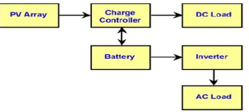
[image:2.612.197.446.509.621.2]Current power plants are heavily dependents on fossil fuel resources. The some disadvantages of fossil fuel resources are emission of environmental pollutants & limited in quantity. India is facing severe energy shortage which is hampering industrial growth and economic progress. Possible solution for all these problems is solar energy system. Solar energy is clean, inexhaustible and environment-friendly potential resource. Also India has huge solar potential. But solar photovoltaic system can’t provide a continuous supply of energy due to seasonal and periodic variations. Therefore, in order to satisfy the load demand, battery connected solar energy systems are now being implemented that combine solar power, battery storage and conventional power. Photovoltaic energy generating system convert the sun’s energy directly into electricity using state-of-the-art semiconductor materials. The “stand-alone or off-grid” system, which means they are the only power source to a home, building, pump or any other load. Stand-alone systems can be designed to run with or without battery backup. Isolated water pumps can be used to work without battery backup, because water pumped out of the ground during day time can be stored in a storage tank for use anytime. In comparison, stand-alone building power systems store energy generated during the day time in the batteries and consume at night. Fig. 1 shows a typical diagram of a stand-alone PV system.
Fig. 1 Typical Stand Alone PV system
446
©IJRASET (UGC Approved Journal): All Rights are Reserved
II. HARDWARE ARCHITECTURE
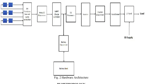
[image:3.612.61.560.207.497.2]Fig. 2 shows the basic block diagram of PV system. The components of the PV system are PV array to capture energy from the sun, MPPT tracker to get the maximum possible power from photovoltaic array, charge controller to control the voltage and the current from the PV array & to prevent under/overcharging of batteries, inverter to Convert the DC power coming from the PV modules or battery bank to AC power, battery bank for storage, LT panel to switch load from PV to Grid and Vice versa. In battery connected system, Batteries store energy generated by array during the day time and consumes at night or during overcast period. The different disconnects (array DC disconnect, inverter DC disconnect, inverter AC disconnect, panel AC disconnect, battery disconnect) are used to isolate respective component in case fault in other component or section. Also other components like Array mounting racks, Grounding equipment, Combiner box, Surge protection (often part of the combiner box), Meters are used for PV system.
Fig. 2 Hardware Architecture
III.METHODOLOGY
System sizing is the procedure of calculating the appropriate voltage, current, KVA & other ratings for individual component of the PV system to meet the electricity demand of building or organization.
A. Factors Affecting System Sizing
1) Average energy requirement in Wh/day by using equipment ratings and their working hours per day which is referred as the
load profile
2) Geographical location that decides the tilt angel, panel positioning, and to obtain the average sun hours per day data.
3) Building design, which plays an important role in maximizing the amount of the generated power by keeping the southern area
free from any obstacle that stops the sun-rays from reaching the panels
4) Use of energy-efficient equipment’s such as LED’s to reduce energy demand. Additionally, hot water and cooking should not
be include in the home photovoltaic system. Recommended to use natural gas for cooking and a separate thermal solar energy system to obtain the hot water directly
5) Use of low-voltage DC electric appliances, these days same are available in the market, which is also a significant factor in
reducing the PV system cost. This will considerably reduce the power rating of the inverter that is used to change the DC power of the batteries into AC power suitable for the conventional appliances.
6) Frequency of switching on and off a rotationary equipment’s such as refrigerators and water pumps. Such loads draws high
447
©IJRASET (UGC Approved Journal): All Rights are Reserved
B. Components Selection and sizing
1) Solar Cell & Module: Calculate average peak output in W/m2 of solar cell by using solar irradiation & peak sun-hours per day for particular location and efficiency of selected material for solar cell. Select solar cell according to the average peak output. Connect solar cells in series or parallel to size solar module(Peak power voltage (Vmp), Peak Power current (Imp), Open circuit voltage (Voc), Short circuit current (Isc), PV Module Capacity
2) Solar Array: Calculate array peak power in KW by using daily average energy requirement & minimum peak sun-hours per day, decide array output voltage to calculate array current, then calculate number of series modules according to the array output voltage & single module rated voltage, parallel modules according to the array output current & single module rated current and total number of modules according to the array output voltage & single module rated voltage, total number of module & space require for the same. The solar array must have a higher voltage than the battery bank in order to fully charge the batteries.
3) Battery Bank: Decide number of Backup days, Battery Maximum depth of discharge (MDOD) to Calculate approx. energy storage requirement form daily average energy demand. Next decide standard battery bank voltage to calculate battery bank capacity in Ampere-hours. Select single battery which available in market, subsequently calculate total number of batteries, number of batteries in series, number of parallel paths.
4) Charge controllers: Charge controllers are selected based on PV array voltage (the controller’s DC voltage input must match the nominal voltage of the solar array), PV array current (The controller must be sized to handle the maximum current produced by the PV array), The charge controller must be selected to deliver the charging current appropriate for the type of batteries used in the system. The charge controller must be set up such that it does not interfere with the proper operation of the inverter. In particular, the controller must be set up such that charging the batteries from the PV array takes precedence over charging from the grid. Also the controller must have overcharging protection, Discharging protection, State-of-charge monitoring, Voltage conversion, MPP tracking.
5) Inverter: Selection criteria of Inverter is:
a) The inverter’s DC voltage input must match the output voltage of the solar array, usually 12, 24 or 48 volts for battery-based
systems
b) The inverter must able to handle load current at rated output voltage
c) The inverter must provide constant output voltage & frequency
d) Inverter should have higher efficiency, around 90%
e) Need to consider High starting current of load like motors
f) For battery connected systems, the inverter can automatically shed any unnecessary loads in the event of a utility power outage.
g) The inverter should have safety integral disconnects
h) The inverter should have warranties of 5 to 10 years
i) If possible inverter cab be integrated with charge controller
j) Safety factor to allow system expand
Based on this select inverter capacity in KVA, calculate output line voltage & phase voltage to design galvanic transformer accordingly.
Maximum Power Point Tracking: MPPT is selected based on Array output voltage, maximum array output current, maximum PV power. MPPT should able to optimize PV output power along with charge controller. Among all available MPP methods, Incremental Conductance (IC) offers a better performance, faster tracking time and has no oscillation. Therefore MPPT is selected based on the same.
IV.HARDWARE DEVELOPMENT & RESULTS
A. Load Calculation
Used 18 no’s of lamp of 60 Watt capacity.
So, Total Wattage= Rating X Nos of Lamp= 18 X 60 =1080 Watt
Daily consumption in KWh = (Wattage X Total load working hours)/1000 = (1080 X 1)/100= 12.96 KWh Total Daily power consumption for LED light will be 12.96= 13 kWh
B. Solar Cell & Module design/sizing/selection
448
©IJRASET (UGC Approved Journal): All Rights are Reserved
Wh/m2/day = solar irradiation / minimum peak sun-hours per day = 5.44 / 5= 1088
Efficiency of multi-crystalline solar cell is 14.7 %, so average peak output = (Wh/m2/day) X solar cell material efficiency= 1080 X 0.147 =160 W/m2
Solar module of 220 Wp is selected for array design, consisting 72 nos of Multi crystalline, full square solar cells connected in series. Specifications of solar module are as below: PV Module Capacity- 220 Wp, PV Module type- Multi crystalline, Module operating Humidity/ temperature- (-40 oC to + 85 oC / 85 %), Peak power voltage (Vmp)- 45.288 V, Peak Power current (Imp)- 5.855 A, Open circuit voltage (Voc)- 40 V, Short circuit current (Isc)- 5.5 A, Module Dimensions- 1325mm X 990mm X 45mm.
C. Solar Array sizing
Daily average energy requirement from the solar array:
ER = daily average energy consumption / product of component's efficiencies
ER =E / ŋoverall = 13/0.75 =17.33 = 17.4 KW-hours
To calculate the Array peak power, divide the daily average energy requirement by the average sun hours per day for the topographical location Tmin i.e. 5 days for Pune.
PP = daily average energy requirement / minimum peak sun-hours per day=ER / Tmin= 17.4 / 5 = 3.48 = 3.5 KW To calculate the array current, divide the peak power by the Array output voltage i.e. 80 V.
IDC = peak power / Array output voltage= PP / VDC= 3500 / 80 = 43.75 A
Number of series modules:
NSM = Array output voltage / rated voltage of each module= VDC/VR= 80 / 40 = 2 Nos
Number of parallel modules:
NPM = Array current / single module rated current = IDC / IR = 43.75/5.5 = 8 Nos
Total number of modules NM:
NM = number of series modules X number of parallel modules = NS X NP = 8 X 2 =16 Nos
D. Sizing of the Battery Bank
The amount of approx. energy storage required:
EAPPROX. = daily average energy requirement / number of backup days= E×DB=13000 X 2 =26000 Wh
For battery safety, approx. energy storage requirement by maximum depth of discharge (MDOD),
ESAFE = energy storage required / MDOD= EAPPROX. / MDOD = 26000 / 0.75 =34666 Wh
Here we are choosing nominal voltage of battery bank is 48 Volts. The capacity of the battery bank:
C= ESAFE / (battery bank voltage X Battery bank efficiency)= ESAFE / (Ŋbatteries X VB)=34666 / 48 * 0.9=800 Ah
Here we are choosing nominal battery of capacity of 200 Ah and 12 Volts. The total number of batteries:
NBATTERIES = capacity of the battery bank / capacity of one battery= C / CBattery= 800/200 =4 Nos
NBM = DC voltage of the Battery bank / single battery voltage= VDC / VB=48/12 =4 Nos
Then number of parallel paths:
NPP = the total number of batteries / number of batteries connected in series= NBATTERIES / NS =4/4 =1
E. MPPT, Charge controller & Inverter Sizing
Charge controller should handle current = Short Circuit current of module X number of parallel X FSAFE = 5.855 X 8 X 1.1= 51 A
MPPT tracker incremental conductance method is selected. MPPT specification: voltage range is 65 V to 130 V (155 V), maximum input current of 51 Ampere. IGBT used as switching element.
The inverter should be such that it handle the output voltage of 80 V generated by the panel. A 3 KW Consul NeoWatt inverter matched all criteria for the project and was capable of supporting 3.5 KW of output. Inverter Specification: 1phase 2 wire, IGBT used as switching element, 32 bit DSP space vector controlled, -2 to +2 % voltage regulation, <2% output voltage distortion with
100% linear load, 0-50 oC as operating temperature, IP20 ingress protection.
Calculations of Inverter Output Voltage.
449
©IJRASET (UGC Approved Journal): All Rights are Reserved
Line Voltage=VL=0.779*48=37.39 Volts KVA rating=KW*P.F. =3*0.85=3 KVA
Inverter output transformer (26 V to 230 Volt) used for galvanic isolation & stepping up the voltage.
F. Hardware Results
1st readings taken at day time when sun is available and PV array is working (Date 14/12/2017, Time: 3:30 PM) 2nd readings taken at Night time when sun is not available and Battery is working. (Date 14/12/2017, Time: 12:30 AM)
TABLEI
HARDWARE TEST RESULTS
Sr. No. Parameter Unit Day Time Night Time
1 PV Voltage V 66.9 3.7
2 PV current A 1.2 0
3 Battery Voltage V 54.4 52
4 Battery Current A 0.5 11.3
5 MPPT Temperature OC 22.4 22.4
6 Load % 49 70
7 PV Power W 80.28 0
8 Output W 1452 2071
9 Battery Power W 32 587.6
10 Inverter Voltage V 230.9 238
11 Output Current A 6.4 9.1
12 Grid Voltage V 233.1 241.6
13 Grid Current A 0 0
14
Inverter
Temperature OC 26.6 22.2
Found all results satisfactory and according to the rating & designed values.
V. HARDWARE DEVELOPMENT & RESULTS
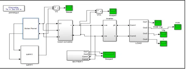
A. Simulation Model of PV System
[image:6.612.161.469.539.653.2]Solar PV system is simulated using MATLAB/SIMULINK,
Fig. 3 Simulink model of PV system
450
[image:7.612.195.429.80.216.2] [image:7.612.193.430.248.436.2]©IJRASET (UGC Approved Journal): All Rights are Reserved
Figure 3 Simulation Results-1
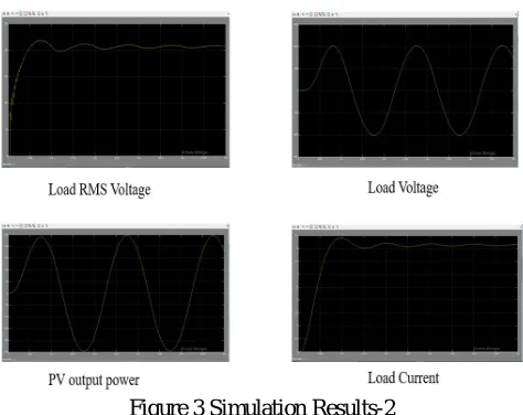
Figure 3 Simulation Results-2
The simulation results are matching with actual behavior of system. Same will be used for sizing of proposed solar plant.
VI.COST BENEFIT ANALYSIS
Total costing of the project was INR 406020 excluding tax slab benefits, average yearly cost saving by solar and LED lights is INR 98792, calculated payback period of 4.10 years.
VII. CONCLUSIONS
The project includes the sizing, selection of various components required for 3.5 KW PV system. All components are installed and connected together to build PV system. The system is tested during day & night time, observed different parameters & & verified with rated quantities to insure proper working of each components of PV system and it was found satisfactory. PV solar system is in operation and it is working according to the expectation. Stand-alone PV systems operate reliably and the best option for many remote applications around the world. Old sodium vapour lamps was replaced with LED for energy conservation and reducing load demand. Finally cost benefit analysis has been done and calculated payback period of 4.10 years.
REFERENCES
[1] Klaus Jager, Olindo Isabella, Arno H.M. Smets, Rene A.C.M.M van Swaaij and Miro Zeman, “Solar Energy: Fundamentals, Technology and systems,” Text Book published in 2014.
[2] “Solar Electric System Design, Operation and installation” the handbook was published in 2009
[3] Payal A. Shinde & V. B. Virulkar, “Sizing of a Stand-Alone Photovoltaic System at Minimum Cost for GCOE, Amravati,” IEEE conferences, 2015 IEEE International Conference On Electrical, Computer and Communication Technologies (ICECCT), pp. 1 - 8, 2015
[4] S. Y. Wong & A. Chai, “An Off-grid Solar System for Rural Village in Malaysia,” IEEE conferences, Asia-Pacific Power and Energy Engineering Conference, pp. 1-4, 2012
451
©IJRASET (UGC Approved Journal): All Rights are Reserved
[6] Răzvan Florin Pantelimon, Maricel Adam, Mihai Andruşcă, Cătălin Pancu, “Aspects Regarding Solar Battery Charge Controllers” IEEE conferences, 8th International Symposium on Advanced Topics in Electrical Engineering,, pp. 1 - 6, May 23-25, 2013.
[7] Swapnil Agarwal & Majid Jamil, “A Comparison of Photovoltaic Maximum Power Point Techniques,” IEEE conferences, IEEE INDICON, pp. 1 - 6, 2015. [8] The report “Global Data: Solar PV Inverter Market, Update 2015- Segmentation, Market Size, Competitive Landscape and Analysis to 2020,” published in
March 2015.
[9] Regine Mallwitz & Bernd Engel, “Solar Power Inverters,” ”, IEEE conferences, 6th International Conference on Integrated Power Electronics System, pp. 1 - 7, 2010.