International Journal of Emerging Technology and Advanced Engineering
Website: www.ijetae.com (ISSN 2250-2459, Volume 2, Issue 4, April 2012)183
Analysis and Implementation of Multi Pulse Converters for
HVDC System
K.Srinivas
Assistant Professor, JNTUH College of Engineering, Nachupally, Kondagattu, Karimnagar, Andhrapradesh, India.
Abstract— It is well known that undesirable harmonic line currents may be generated during a transformer-rectifier combination. The rectification of AC power to DC power itself may in general produce undesirable current harmonics. These non-linear loads cause severe current harmonics that may not be tolerated by either a shutdown of the device or unacceptable powering of the devices. The great majority of power electronic equipment operates from an ac source but with an intermediate dc link. Thus, a significant opportunity exists to facilitate power electronics applications by using ac to dc rectifiers that produce low harmonic current in the ac source. Multi-pulse converters in general and non-isolated multi-pulse converters in particular can be applied to achieve clean power which is of major interest in higher power ratings. In general, by increasing the number of pulses in multi-pulse converters THD (total harmonic distortion) can be reduced and other associated performance parameters can be enhanced.
The present work is an endeavour towards analysing the different multi-pulse AC to DC converters in solving the harmonic problem in a three-phase converter system. The effect of increasing the number of pulses on the performance of AC to DC converters is analyzed. For performance comparison the major factor considered is the total harmonic distortion (THD).
Keywords— Power Quality, Harmonics, Total Harmonics Distortion
I. INTRODUCTION
Power electronic devices are non-linear loads that create harmonic distortion and can be susceptible to voltage dips if not adequately protected. The most common economically damaging power quality problem encountered involves the use of variable-speed drives. Variable-speed motor drives or inverters are highly susceptible to voltage dip disturbances and cause particular problems in industrial processes where loss of mechanical synchronism is an issue. THREE-PHASE ac–dc conversion of electric power is widely employed in adjustable-speeds drive (ASDs), uninterruptible power supplies (UPSs), HVDC systems, and utility interfaces with non conventional energy sources such as solar photovoltaic
systems (PVs), etc., battery energy storage systems (BESSs), in process technology such as electroplating, welding units, etc., battery charging for electric vehicles, and power supplies for telecommunication systems. Traditionally, ac–dc converters, which are also known as rectifiers, are developed using diodes and thyristors to provide uncontrolled and controlled unidirectional and bidirectional dc power. They have the problems of poor power quality in terms of injected current harmonics, resultant voltage distortion and poor power factor at input ac mains and slowly varying rippled dc output at load end, low efficiency, and large size of ac and dc filters.
The present work is an endeavor towards analyzing the different multi-pulse AC to DC converters in solving the harmonic problem in a three-phase converter system. The effect of increasing the number of pulses on the performance of AC to DC converters is analyzed. For performance comparison the major factor considered is the total harmonic distortion (THD). The effect of load variations on multi-pulse AC to DC converters has been investigated.
II. BASIC HVDCSYSTEM CONFIGURATIONS
International Journal of Emerging Technology and Advanced Engineering
Website: www.ijetae.com (ISSN 2250-2459, Volume 2, Issue 4, April 2012)184 Fig. 1.1 Back-to-back interconnection
Fig. 1.2 Monopolar link
[image:2.612.73.391.99.708.2]Fig. 1.3 Bipolar link
Fig. 1.4 Parallel 3-terminal
Fig. 1.5 Series connection
The bipolar link is the most common configuration and has two conductors or poles. One of the conductors or pole is positive with respect to the other. The current from the rectifier flows through the positive pole and from the inverter flows through the negative pole. However, the return path is through the ground and hence the opposite currents cancel each other and the ground current is practically zero. In the parallel- connected three-terminal configuration, converters 1 and 2 operate as rectifiers and converter 3 operates as an inverter. However, by changing the firing angle control and the polarity of voltage, converters 1 and 2 operate as inverters and 3 as a rectifier. The series connection, although still unused, is an attractive proposition for small taps because of comparatively high cost of the full voltage parallel tapping alternative [1].
III. CONVERTER OPERATION
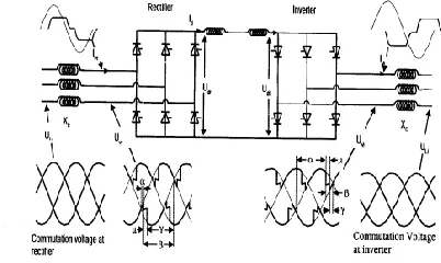
The six-pulse converter bridge shown in the fig.3.1 is used as the basic converter unit of HVDC transmission rectification where electric power flows from the ac side to the DC side and inversion where the power flow is vice versa. Thyristor valves conduct current on receiving a gate pulse in the forward biased mode. The thyristor has unidirectional current conduction control and can be turned off only if the current goes to zero in the reverse bias. This process is known as line commutation. Inadvertent turn-on of a thyristor valve may occur once its conducting current falls to zero when it is reverse biased and the gate pulse is removed. Too rapid an increase in the magnitude of the forward biased voltage will cause the thyristor to inadvertently turn on and conduct [1]. The design of the thyristor valve and converter bridge must ensure such a condition is avoided for useful inverter operation.
[image:2.612.335.536.539.659.2]International Journal of Emerging Technology and Advanced Engineering
Website: www.ijetae.com (ISSN 2250-2459, Volume 2, Issue 4, April 2012)185
IV. REVIEW OF MULTI-PULSE CONVERTERS
A large number of publications have appeared in the field of multi-pulse converters, many giving new concepts and verifying their claims by simulations and experimental work. Paice [1] proposed maximizing the efficiency of a 12 pulse AC-DC converter based on a hexagonal autotransformer arrangement. Choi [2] in his paper has presented new autotransformer arrangements with reduced KVA capacities are presented for harmonic current reduction and to improve AC power quality of high current DC power supplies. Simulation results are given in the paper. Falcondes and Babri [3] has proposed a new isolated high power factor 12 KW power supply based on 18-pulse transformer arrangement .the topology used involves a simple control strategy .simulations and experimental results are given in paper.
S.Kim Etal [4] has given an analysis and design of a passive and novel interconnection of a star/delta transformer approach to improve power factor and reduce harmonics generated by a three phase diode rectifier. Chen Etal [5] has proposed a new passive 28-step current shaper for three phase rectification .with a phase shifting transformer on the ac side, per phase input current is shaped into sinusoidal waveform. Tolbert [6] his work provides the cascade inverter for large automotive drives. Here back to back diode clamped converter is used, simulation and experimental results are given in paper. This chapter presented a review of available literature on power quality improvement pertaining to AC/DC converters. The next chapter presents a detailed study of multi-pulse converters.
A. Multi-Pulse methods
The term multi-pulse method is not defined precisely. In principle, it could be imagined to be simply more than one pulse. However, by proper usage in the power electronics industry, it has come to mean converters operating in a three phase system providing more than six pulse of DC per cycle.
Multi-pulse methods involve multiple converters connected so that the harmonics generated by one converter are cancelled by harmonics produced by other converters. By this means, certain harmonics related to number of converters are eliminated from the power source. In multi-pulse converters, it is assumed that the DC link uses a filter such that any ripple caused by the DC load does not significantly affect the DC current.
Multi-pulse systems result in two major accomplishments namely,
1. Reduction of ac input line current harmonics.
2. Reduction of DC output voltage ripple.
Reduction of ac input line current harmonics is important as regards the impact the converter has on the power system.
Multi-pulse methods are characterized by the use of multiple converters or multiple semiconductor devices with a common load.
Phase shifting transformers are an essential ingredient and provide the mechanism for cancellation of harmonic current pairs, e.g. the 5th and 7th harmonics or the 11th and 13th so on. Thus for harmonic current reduction the multi-pulse converters are fed from phase shifting transformers. The phase shift has to be appropriate.
B. Zig-Zag Phase shifting transformer
The Zigzag Phase-Shifting Transformer implements a three-phase transformer with a primary winding connected in a zigzag configuration and a configurable secondary winding. The model uses three single-phase, three- winding transformers. The primary winding connects the windings 1 and 2 of the single-phase transformers in a zigzag configuration. The secondary winding uses the windings 3 of the single phase transformers and they can be connected in one of the following ways: Y with accessible neutral Grounded Y Delta (D1), delta lagging Y by 30 degrees Delta (D11), delta leading Y by 30 degrees. If the secondary winding is connected in Y, the secondary phase voltages are leading or lagging the primary voltages by the Phi phase angle specified in the parameters of the block. If the secondary winding is connected in delta (D11), an additional phase shift of +30 degrees is added to the phase angle. If the secondary winding is connected in delta (D1), a phase shift of -30 degrees is added to the phase angle.
V. MAT LAB SIMULATION
A. Twenty-four pulse converter (un-controlled)
International Journal of Emerging Technology and Advanced Engineering
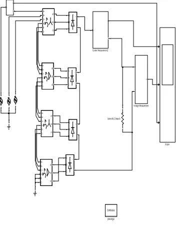
Website: www.ijetae.com (ISSN 2250-2459, Volume 2, Issue 4, April 2012)186 One approach is to provide 15 degrees phase shift windings on the two transformers of one of the two twelve pulse converters. Another approach is to provide phase shift windings for +7.5 degrees phase shift on the two transformers of one twelve pulse converter and -7.5 on the two transformers of the other two twelve pulse converters as shown in the fig. The latter is preferred because it requires transformers of the same design and leakage inductances. It is also necessary to shift the firing pulses of one twelve pulse converter by 15 degrees with respect to others.
All four six-pulse converters can be connected on the DC side in parallel, i.e., twelve phase legs in parallel. Alternatively all four six-pulse converters can be connected in series for high voltages or two pair of twelve pulse series converters may be connected in parallel. Each six-pulse converters will have a separate transformer, two with wye-connected secondaries and the other two with delta-connected secondaries. Primaries of all four transformers can be connected in series as shown in Fig.. In order to avoid harmonic circulation current corresponding the twelve pulse order i.e., 11th, 13th, 23rd, 25th
Continuous pow ergui
A+ B+ C+ A- B-
C-a3 b3 c3
A+ B+ C+ A- B-
C-a3 b3 c3 A+ B+ C+ A- B-
C-a3 b3 c3
A+ B+ C+ A- B-
C-a3 b3 c3
v +
-Voltage Measurement
A B C + -A B C + -A B C + -A B C +
-Series RLC Branch
Scope
i
+
-Current Measurement2
i
+
[image:4.612.333.532.146.510.2]-Fig. 5.1.Uncontrolled 24 pulse converter
Fig. 5.2 Uncontrolled 36 pulse converter
B.
Simulation of Controlled Multi-Pulse Converters
[image:4.612.75.252.405.631.2]International Journal of Emerging Technology and Advanced Engineering
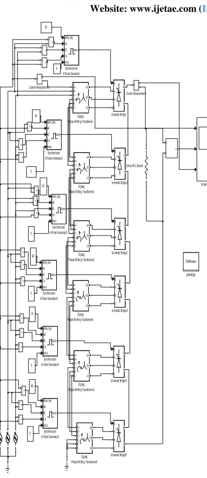
Website: www.ijetae.com (ISSN 2250-2459, Volume 2, Issue 4, April 2012)187 Continuous powergui A+ B+ C+ A- B- C-a3 b3 c3 Zigzag Phase-Shifting Transformer5 A+ B+ C+ A- B- C-a3 b3 c3 Zigzag Phase-Shifting Transformer4 A+ B+ C+ A- B- C-a3 b3 c3 Zigzag Phase-Shifting Transformer3 A+ B+ C+ A- B- C-a3 b3 c3 Zigzag Phase-Shifting Transformer2 A+ B+ C+ A- B- C-a3 b3 c3 Zigzag Phase-Shifting Transformer1 A+ B+ C+ A- B- C-a3 b3 c3 Zigzag Phase-Shifting Transformer v + -v + -v + -v + -v + -v + -v + -v + -v + -v + -v + -v + -v + -v + -v + -v + -v + -v + -v + -g A B C + -Universal Bridge5 g A B C + -Universal Bridge4 g A B C + -Universal Bridge3 g A B C + -Universal Bridge2 g A B C + -Universal Bridge1 g A B C + -Universal Bridge alpha_deg AB BC CA Block pulses Synchronized 6-Pulse Generator5 alpha_deg AB BC CA Block pulses Synchronized 6-Pulse Generator4 alpha_deg AB BC CA Block pulses Synchronized 6-Pulse Generator3 alpha_deg AB BC CA Block pulses Synchronized 6-Pulse Generator2 alpha_deg AB BC CA Block pulses Synchronized 6-Pulse Generator1 alpha_deg AB BC CA Block pulses Synchronized 6-Pulse Generator
Series RLC Branch
[image:5.612.57.267.116.600.2]Scope i + -Current Measurement1 i + -Current Measurement 70 0 0 60 50 0 0 40 80 0 0 30
[image:5.612.327.560.149.309.2]Fig. 5.3.Controlled 24 pulse converter
Fig. 5.4 Uncontrolled 36 pulse waveform of input current, output
[image:5.612.327.564.361.491.2]voltage, output current
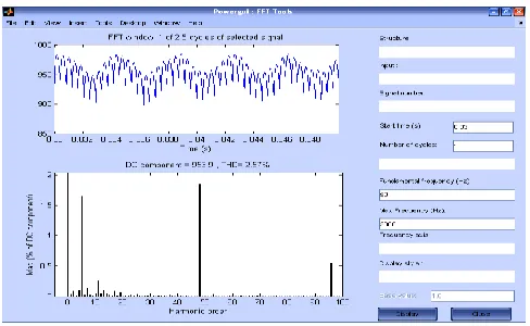
Fig. 5.5 Uncontrolled 36 pulse THD for input current
[image:5.612.325.564.518.638.2]International Journal of Emerging Technology and Advanced Engineering
Website: www.ijetae.com (ISSN 2250-2459, Volume 2, Issue 4, April 2012) [image:6.612.321.562.105.284.2]188 Fig. 5.7 Controlled 36 pulse waveform of input current, output
[image:6.612.55.282.139.285.2]voltage, output current
Fig. 5.8 Controlled 36 pulse THD for input current
[image:6.612.326.563.332.481.2]Fig.5.9 Controlled 36 pulse THD for output voltage
Fig. 5.10 Controlled 48 pulse Output waveform of input current,
output voltage, output current
Fig. 5.11 Controlled 48 pulse THD for input current
Fig.5.12 Controlled 36 pulse THD for output voltage
[image:6.612.50.285.347.492.2] [image:6.612.323.567.515.665.2] [image:6.612.47.290.524.685.2]International Journal of Emerging Technology and Advanced Engineering
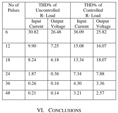
Website: www.ijetae.com (ISSN 2250-2459, Volume 2, Issue 4, April 2012) [image:7.612.65.271.288.485.2]189 The uncontrolled 36 pulse converter input current, output voltage and current shown in Fig. 5.4 the corresponding THD% has been show in Fig.5.5 and Fig.5.6 which is observed that the THD in input current is little high as compare to output voltage. For the same controlled converter 36 pulse as has been shown in Fig. 5.7, and corresponding THD shown in Fig. 5.8 and Fig. 5.9 the comparative THD in both controlled and uncontrolled shown in table I from this, the THD% is reduces for increasing number of pulses both in controlled and uncontrolled converters.
Table I. Comparison of THD% in uncontrolled and controlled converter
No of Pulses
THD% of Uncontrolled
R- Load
THD% of Controlled R- Load Input
Current
Output Voltage
Input Current
Output Voltage 6 30.82 26.48 36.09 25.82
12 9.90 7.25 15.08 16.07
18 8.24 6.18 13.34 18.07
24 1.87 0.36 7.34 7.88
36 0.26 0.16 4.30 3.36
48 0.21 0.14 3.21 2.57
VI. CONCLUSIONS
The various multi-pulse configurations, mainly non-isolated were simulated using the software SIMULIN/MATLAB and the results have been presented. The effect of load variation on different multi-pulse converters reveals that with RL, load because of inductance there is smoothing effect on current, therefore current THD decreases; whereas on RC load, the effect of capacitor is to reduce voltage ripple and gives a smooth DC output. The effect is similar for different multi-pulse converters.
The main objective of the present work is to investigate the performance of controlled and un-controlled multi-pulse converters. These converters are studied in terms of harmonic spectrum of ac mains current, output voltage THD. It is concluded that in general with increase in number of pulses in multi-pulse case the performance parameters of these converters are remarkably improved.
VII. REFERENCES
[1] D.A.Paice. ―Auto connected hexagon transformer for a 12-pulse converter‖. Patent number: 5148357. 1992.
[2] Choi dewan, enjeti, pitel ―autotransformer configurations to enhance utility power quality of high power AC/DC rectifier systems.‖1996 IEEE.
[3] Babri Ivoand Jones, ―a new three –phase low THD supply with High –frequency isolation and 60v/200A regulated DC supply‖. 2001. IEEE
[4] S.Kim, Enjeti,‖A new approach to improve Power Factor and reduce Harmonics in a Three-Phase Diode Rectifier Type Utility Interface‖IEEE trans.on Industry appl,Vol.30,No.6,NOV/DEC 1994.
[5] Chen and Hong, ―A new passive 28-step current shaper for three-phase rectification.‖IEEE transactions on industrial electronics, vol.47, No.6, December 2000
[6] N.R.Zargari etal, ―A multilevel thyristor Rectifier with improved power factor‖ IEEE trans.on industry applications, vol.33.No.5, SEPT/OCT. 1997.
[7] D.A.Paice, Power Electronic Converter Harmonics- Multipulse Methods for Clean Power. New York: IEEE Press, 1996..
[8] N.Mohan, TUdeland and W.Robbins, Power Electronics Converters, Applications and Design, Second Edition, New York: John Wiley & sons, 1995