Aspects
of
I
ntegrated
D
esign
of
S
tructures:
P
arametric
M
odels,
C
reative
S
pace
and
L
inked
K
nowledge
Abstract
In the construction industry, collaborative working methods with overlapping domains have been developing side by side with information and commu-nication technology. Recently, efforts have been made to combine these methods in order to facilitate the integration of disciplines. Research on collaborative work has resulted in the promising “integrated project delivery” methodology, whereas research on information and communication technology has resulted in building information modelling. In this paper, we propose three principles for integrated design: “parametric models”, “creative space” and “linked knowledge”. These principles have been derived during the course of the TailorCrete Project. The project involves contributions from architects, structural engineers, contractors and building material manufacturers, as well as scientists of the built environment. All principles are elaborated upon with regard to their connection to integrated design and how they are carried out in practice; the elaboration is based on results collected from the TailorCrete project and from research results found in the literature. This paper concludes that parametric models, creative space and linked knowledge are the three main aspects that should be pursued in order to achieve and implement a practical integrated design process.Keywords
design process, complex shapes, re-inforced concrete, system engineering, architectual engineering, structural architecture, computer aided design, knowledge-based engineering, generative design1
Introduction
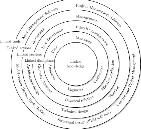
The success of a complex construction project derives from a well-planned design and is dependent on highly trained specialists. A well-integrated design results from a design team capable of grasping the factors impact-ing a chosen strategy. These factors derive from the flow of information at all levels of the construction in-dustry and the understanding of challenges met in the
separate domains of each discipline. Figure 1 illustrates the interacting disciplines and actors who process, de-velop and carry out the communication of the project. Furthermore, the communication domain is divided into sub-domains of each discipline that address the link-age of services, actions and tools. Knowledge sharing
M o d el cr ea tor (R h in o,R ev it,T ekla)
Structural design (FEMsoftw
are) Con stru ctio nP roje ct M a n ag e m en t Project Ma nagemen t S oftw are Ass et Man agem
ent S oftwa re A rch it ec tu ral d esig n Technical design Pla nn ing Management Inv estm ent G eom et ry, fun ctio n
Technical solution
[image:1.595.315.550.369.583.2]Eff ecti ve pro du ctio n Effective mana gem ent Low dist urba nce A rch it ec ts Engineers Con tra cto rs Managers Use rs Linked disciplines Linked services Linked actions Linked tools Linked knowledge
Figure 1. Communication in civil engineering and levels of
com-munication vehicles.
across domains has been debated for a long time, but recently integrated design and collaborative design have emerged as promising working methodologies [1,2]. Al-though the implications have been investigated [3], the research needs to put more efforts into discussing the ac-tual principles of integrated design. However, there have been suggestions of formal approaches to which this pa-per attempts to contribute, including Mora [4] who tried to bridge the “no man’s land” between traditional dis-ciplines and the architectural domain.
The aim of this study has been to identify the main principles of integrated design of structures and to pro-pose practical methods that by which a learning culture in a project organisation may be promoted.
Rasmus Rempling
*, David Fall, Karin Lundgren
Chalmers University of Technology, Civil and Environmental Engineering, Structural Engineering, SE-41296 Gothenburg, Sweden
Copyright © 2015 by authors, all rights reserved. Authors agree that this article remains permanently open access under the terms of the Creative Commons Attribution License 4.0 International License
Civil Engineering and Architecture 3(5): 143-152, 2015
This study was part of the TailorCrete Project1
in-cluding the contribution of scientists, architects, con-tractors, and structural engineers. Although the focal point has been on the interaction between structural en-gineers and other actors, a need for generalisation on a higher level has emerged. The main contribution of the project partners turned out to be the case study exam-ple used for the automated routine design methodology. The case was a double curved wall constructed in Va-lencia, Spain.
2
Creative space, communication
technology and team
integra-tion
The researcher Tatum [5] highlights the importance of technical support activities that involve all actors in order to ensure an effective construction process. How-ever, to expand the traditional concept of construction engineering the activities need to include integration and innovation, as well as making the pre-construction ac-tivities more prominent. Although his research early pointed out the benefits of automating the design and building activities, this goal has not yet been reached [6]. The information that is communicated among the ac-tors and the possibility of integration depend on the level on which the integration is made. The researcher Moum [7] defines three hierarchical project levels: macro-, me and micro-level in order to represent different so-cial constructions. The macro-level incorporates all par-ticipants of a construction project: architects, engineers, contractors and users. This conglomerate of stakehold-ers with separate interests and expectations is boiled down to a design team with the mandate to uncovering the mutually beneficial expectations of the stake-holders (meso-level). Finally, Moum defines the micro-level as the collaborative space between the architect and the engineer. This framework has then been applied to a number of projects in order to study their level of inte-gration, the impact of information and communication technology (ICT) on the progress of these projects, as well as highlighting the non-technical parameters influ-encing integration. Moum’s study focused on the micro-level and concluded that if the understanding of aims and intentions were shared and the skills of the ICT software were substantial, the collaboration and inte-gration of architects and engineers would progress. In addition, her results highlighted the fact that soft non-technical parameters, such as an architect’s sources of inspiration, are easily punctuated by the introduction of ICT and that these parameters must be better under-stood in order to attain a successful implementation and use of ICT [7].
The introduction and adoption of new technologies have been proven difficult to manage and not fast enough. In [8,9] strategies for the adoption of new tech-nologies are considered necessary and the adoption of new technology depends on four drivers: competitive ad-vantage, process problems, technology opportunity and external requirements. In their study, they conclude
1http://www.tailorcrete.com/
that if these four factors were to increase, the rate of adoption would increase as well [8,9]. However, the fac-tors are client- and top-management dependent, which may lead to implications of social integration on the micro-level that are not easily predictable. In addition, the potential opportunities and pitfalls of such integra-tion have been studied in a series of eleven case stud-ies [10].
The results of [7] point out that the integration of the architect and the engineer implies that the traditional domains of these professionals overlap. Such overlap-ping domains were further addressed by Mora and co-workers at the University of Quebec [11] who concluded that improved engineering feedback would be required early in the design process, which may be achieved by an improved collaboration between the architect and the engineer. Increased feedback would require overlapping domains that constitute a space in which the engineer can lay out a structural system in an architectural con-text [11]. In addition, the work of the engineer and its quality is highly dependent on the amount, quality and type of information the architect provides.
Mora [11] laid out the representation of the informa-tion into separate domains in the form of two types of entities: functional and physical. Functional enti-ties refer to what the object is intended accomplish, whereas physical entities make up the structural compo-nents providing the function. The architectural domain was concluded to consist of purely functional entities describing the intentions of the architect complemented by the physical entities represented by the structural domain [11]. Consequently, the engineer should have the opportunity to smoothly transition from the phys-ical structural representation to the functional, a tran-sition that would depend on the need for high quality information [7].
According to Mora [11] the overlapping of domains should be strictly carried out during the early stage of the design process, defined as the “conceptual stage”. Mora defines building design process by three stages: conceptual design, preliminary design and detailed de-sign. Krish [12] chose a more general definition of the design process but addressed the conceptual stage as an “early stage of design”. In seeking a definition of this flexible and creative stage of the design process, Verha-gen [13] chose to name it the “innovative design stage” as opposed to the “routine design stage”.
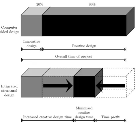
In conclusion, these research results highlight the fact that if the routine design activities were to a higher de-gree automated, together with innovative tools and pro-cesses, the innovative stage might become decisive. This conclusion is important in order to reach an optimal so-lution that might create a larger soso-lution space, as well as narrowing the problem space early during the process (Figure 2).
2.1
Main methodologies for social integrationof meso-level collaboration
20%
Computer aided design
80%
Innovative
design Routine design
Overall time of project
Integrated structural design
Increased creative design time
Minimised routine
[image:3.595.63.299.40.253.2]design time Time profit
Figure 2. To gain time, all disciplines should strive for an
au-tomation of routine tasks, such as reinforcement design of rein-forced concrete structures, redrawn from [13].
Computer-aided design (CAD) has become omnipo-tent. In today’s design projects, the architects and en-gineers use advanced software and algorithms to inves-tigate a variety of design alternatives. In certain cases computer-aided design makes use of automated routine design tasks, but only few integrate domains, as re-ported in [14]. On the other hand, there is a continuous growth of the stakeholders requirements. Today, stake-holders demand specific industrialised solutions while quality is maintained. Verhagen and co-researchers [13] have studied mass customisation from the viewpoint of knowledge-based engineering. In the knowledge-based engineering methodology, the overlapping of domains missing in the CAD process are considered to be inte-grated by a centralised representation of the knowledge [13,15] and [16]. In the construction industry, such cen-tral representation of knowledge is referred to as “build-ing information modell“build-ing”. The benefit of central rep-resentation of knowledge offers improved opportunities for overlapping domains that might generate alternative solutions.
However, the increase of alternative solutions calls for methodologies that are capable of selecting from a num-ber of alternatives. Researchers from Korea [17] pro-posed a design procedure that focuses on the selection of alternatives and the integration of actors from different disciplines. These researchers concluded that through the integration of actors and systematic modelling of alternatives, the design might be improved and the pro-cedure become more flexible, which would help decision-making [17]. Krish [12] has taken this further, by intro-ducing a practical and generative design method sprung from the development of procedural and parametric sign processes. This method focuses on the creative de-sign stage and combines functional and physical entities, enabling specialists to render opinions while computer algorithms perform routine design tasks [12].
2.2
The incompatible purposes ofgeometri-cal and numerigeometri-cal representations of dis-ciplines
Representations of structural objects have mainly been used for visualisation and production purposes and have been presented in a form suitable for the commu-nication of abstract and concrete ideas. The task of an architect is to present a model that gives clients an im-age of the projected idea, whereas the purpose of an engineer is to convert such an image into a structure. In recent years, the use of computer models has been opening the doors to the integration of different disci-plines [1,3,17–31].
While, the need for integrating disciplines remains, the integration through computer software has become a hindrance due to the lack of available and adequate computer software, as well as the diverging purposes of the models. In Figures 3 and 4, these diverging purposes are exemplified. The geometrical and functional mod-els are used for the visualisation and division of space, whereas the structural models are used for calculation purposes. In order to visualise an object in the func-tional space, height, width and depth are needed, while in order to perform calculations in a structural space, the same parameters are included as sectional parame-ters: i.e. stiffness matrix, moment of inertia and first moment of area.
Width Length
Height
nyx nx
vx
mx myx
ny nxy
vy my
mxy y
x z
[image:3.595.313.552.385.483.2]a b
Figure 3. The purpose of a geometrical representation (a) is to
divide space and define the functions of a structure, whereas the purpose of the numerical representation (b) is to idealise a struc-tural system and extract stress components that may be used for structural design. The geometrical representation of shell struc-tures is mainly constructed by solids (◦) whereas the numerical representation is idealised by shell elements () as thin structural elements.
a b
Figure 4. In the structural representation, the lack of physical
meaning of objects results in uncoupled elements (b) whereas in reality solids are firmly connected (A). The connection of elements () is a necessity for the performance of structural analyses.
[image:3.595.314.551.588.739.2]2.3
Collaborative working in the construction industryChanges and unexpected hurdles are commonplace in any project, yet they cause stress and conflict. Col-laborative working is generally accepted, including in-teraction with legislators and governmental authorities to prevent project delay. Generally, a successful col-laborative design process requires a combination of fac-tors, including early involvement, a focus on value, the measurement of performance and long-term trusting re-lationships. Within a collaborative design team, open communication is vital to a successful project. The sci-entific community [32] has reached a consensus on the fact that “Integrated Project Delivery” is the preferred organisational structure.
Integrated project delivery is based on a team that shares the project contract and, therefore, assumes a joint risk for the project. However, as pointed out by [2], it is not the shared contract in and of itself, but rather the level of devotion to the project goals that is beneficial to the successful completion of the project.
The integration of collaborative tools into any form of multi-discipline project delivery is highly desirable. Researchers at TongJi University [21] suggest a combi-nation of building information modelling and Integrated Project Delivery to create an overall method that up-grades the poor performance of the industry. They high-light the effectiveness of this combination of tools and processes but unfortunately do not complement their proposal with practical implementation [21]. However, these types of initiatives are critical in order to attain a more creative design process.
How can trust be created among team members? And, how can team members become comfortable in their roles and responsibilities? In a study of Tatum [33], construction engineering was identified as a series of ac-tivities that includes a productive environment and the transfer of skills. Such construction engineering activi-ties were considered paramount for project success and increase most likely the potential for integration [33].
In this paper, we are proposing linked knowledge to be a key aspect leading to collaborative working. By “linked knowledge”, we refer to the understanding and specific information that link the disciplines in a specific project.
All project delivery methods share the communica-tion of informacommunica-tion. Further, all methods underline that project team members should strive to achieve and reach project goals, a task requiring an understanding of the strategic goals of the other disciplines represented on the project team.
If the “understanding” of strategic goals were deliv-ered with project specific “information”, shared knowl-edge might be created; we propose that understanding and information are specified by linked knowledge of each discipline, respectively.
3
Linking knowledge for
collabo-rative creative thinking
The researcher Johansson [34] at the Chalmers Uni-versity of Technology has performed an depth in-vestigation of the factors that facilitate and hinders the sharing of knowledge across professional boundaries in the construction field. She pointed out that di-verging knowledge and poor information-sharing prac-tices were major hurdles. The diverging knowledge was mainly attributed to diverging perspectives and strategic goals, whereas traditional communication ve-hicles such as project meetings, document circulation and drawings resulted in poor communication practices. The differing perspectives and diverging strategic goals were mainly attributable to organisational tradi-tion and type of profession. If practitradi-tioners were lib-erated from their organisations and professional mind-sets of “how things should be done”, the focus on and willingness to negotiate a solution to common problems immensely increased [34].
In opposition to [34], Sense [35,36] examined how project teams may serve as melting pots for multi-disciplinary knowledge in order to unlock learning cul-tures and suggested that knowledge creation within a project team should take on the role of an organised project action.
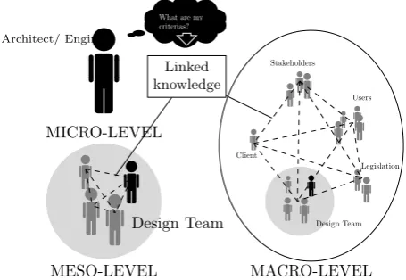
We propose linked knowledge as a solution in order to make knowledge creation into an organised project ac-tion in design projects. Linked knowledge implies infor-mation and understanding of one’s own discipline need to be communicated to other disciplines. In addition to understanding strategic goals and perspectives (personal and organisational), information that is possible versus impossible to digitise (e.g. reinforcement amount and type versus policy documents) should be identified early on by project team members, preferably in the context of a so-called “ individual ideation process” [37]. This linked knowledge is changing with the receiving partner or level, as depicted in Figure 5, in which the proposed knowledge linkage is added to the framework developed by [27].
MESO-LEVEL
Design Team What are my criterias?
MICRO-LEVEL Architect/ Engineer
Linked knowledge
Design Team
MACRO-LEVEL Users Stakeholders
[image:4.595.323.551.572.729.2]Legislation Client
Figure 5. The architect or engineer needs to identify the project
4
Creating space for
collabora-tive creacollabora-tive space
As stated in the previous section and emphasised by [35,36], today’s project arrangement offers little room for creative space in success of either length of project time or budget. Except for exceptional circumstances, stakeholders are not keen on giving additional financing for finding optimised solutions. In order to create space, the period, systems, processes and products of a project need to be developed.
Within the TailorCrete Project, researchers, archi-tects, structural engineers and contractors strove to find new industrial technologies for tailor-made concrete structures manufactured at mass customised prices. During the project, architectural free-form concrete structures met industrialised techniques and processes to arrive at such methodologies as digital design, rein-forcement, automation technologies in construction and advanced casting techniques.
In the following sections, the aspects as a result of the project are presented.
4.1
Integrated parametric design approachIn any design task, the configuration of the geometri-cal model depends on the complexity of the structural system that should be numerically analysed. In this project, parametric design is defined as a collaboration between architects and structural engineers by means of key parameters, e.g. column size, slab thickness and wall height.
In the proposed parametric design approach, it is sug-gested that the architect is responsible for the geometri-cal model, which should be based on the key parameters provided by the structural engineer.
In Figure 6, three parametric design approaches (A, B, C) are illustrated with increasing complexity of the structural system. The difference in correlating the models between the alternative approaches is caused by the available numerical simplification of the load-carrying system. At the same time, the choice of model depends on the context of the structural member. This complexity shows the importance of integrating the dis-ciplines and of communicating the knowledge linkage.
The approaches are described below and are illus-trated in Figure 6.
A The first approach is the most straight-forward in which the geometrical model correlates with the nu-merical model. In addition to the power of para-metric objects, this approach results in a flexible design process by which routine design tasks can be automated to clear space for the innovative stage. Nilsson and Nilsson [38] studied this correlation in the context of linking tools and concluded that an existing compatibility increased flexibility and facil-itated communication.
B Should the numerical analysis need to be idealised by shell elements to compute in-plane stresses, there would no longer be a correlation between the geo-metrical and numerical models. However, the sec-tional and numerical models still correlate and as
in the first approach, the sectional model has the advantage of being parametric.
As a matter of fact, the skill of modelling the ge-ometrical model was increased together with the need for iterations between the architectural and structural domain, i.e. in the first approach, the numerical connections were defined between struc-tural members of the geometrical model. In this ap-proach, the numerical connection exists in the sec-tional model, albeit without geometrical meaning. There is no obvious approach by which this task may be automated and more development is called for.
C Normally, there is minor or no integration of do-mains in today’s design project and the approach with no direct correlation between any of the mod-els is the most common. Architects tend to model the geometry by non-parametric volumes followed by engineers who remake these models to include the parameters needed for numerical computations. In this approach, the automation of routine design tasks is minimal. If the numerical computation could be effectively performed by means of solid el-ements, the geometry might be translated or even meshed in the most common modelling software; however, this is normally not the case. In many practical instances, the numerical models need to be represented by shell elements. If the numer-ical models were composed of shell elements, the computation of sectional resistance might be auto-mated. An example of automating the computation of needed reinforcement is shown in Section 4.2.
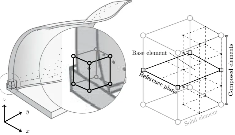
It is tempting to search for a solution outside the three common approaches, A, B, C, by which the numerical analysis would be performed on a solid. However, the complications are still too large to be overcome. An approach that has surfaced lately is the so-called “com-posed solid elements” (Figure 7) that is based on reg-ular solid elements and is specified through a base el-ement referred to as the middle layer, i.e. the same as a shell element. In this way, the composition repre-sents the thickness of an architectural model. Still, this approach merely represents a post-processing analysis, which makes the automation process cumbersome [39].
4.2
Automated routine design tasks based onparametric design principles
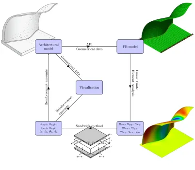
To study the constraints of the most common ap-proach, approachC, a fictitious automatised design pro-cess was conducted. The designed object was composed of a shelter with a double curved shell mounted on a base plate. The material in both sections was reinforced concrete. To be able to calculate sectional forces, the architectural model needed to be converted to a numer-ical model, which in the current scenario constitutes a shell structure.
The first of several design iterations is presented below and in Figure 8.
1. First, an architectural model was created solely for visualisation. The model was represented by
Increasing complexity of correlated models−→
Approach A Approach B Approach C
Linear element, simple section Linear element, complex section Free form structure
P
arametric
represen
tation
y
x z
y
x z
y
x z
Sectional
represen
tation
E.g.: small sections
y
x z
E.g.: large sections
y
x z
For a free-form structure, no sectional repre-sentation exists
Numerical
represen
tation uz
ux uy
θx
uy
ux uz
θx
y
x z
y
x z
y
[image:6.595.56.552.38.457.2]x z
Figure 6. Illustration of representation of three examples with increasing correlation of complexity on parametric, sectional, and
numerical levels.
y
x z
Solid elemen
t Reference
plane
Base element
Comp
osed
elemen
ts
Reference
plane
y
x
z
Solid
elemen
t
Reference
plane
Base element
Comp
osed
elemen
ts
Reference
plane
Figure 7. The composed element approach that is available in some finite element software uses the results from a representation of
[image:6.595.113.497.507.728.2]Uniform Rational B-Spline (NURBS), a very com-mon and widely accepted geometric representation.
2. However, NURBS have no parametric intelligence that may be used for computing the sectional forces. Therefore, a conversion from an architectural to a numerical model was required. This conversion was achieved by making a script (developed in the application-programming interface of the software used).
3. The script generated an input file to the engineering framework holding the mid-surface data of the two shells. This file was imported and meshed to create a model suitable for finite element analysis.
4. The finite element solver computed the sectional forces by means of Linear Finite Element Analysis.
5. The sectional forces were used by an engineer to compute the sectional resistance and the need for reinforcement through a rational design method for conventional reinforcement as presented in [40].
6. The amount of required reinforcement could then be estimated by the number of bars and sent back to the architectural model.
7. The solution could be optimised by several itera-tions.
In the specific case-study shown in Figure 8, the ar-chitectural software Rhino [41] and the finite element solver DIANA [39] were used.
The process of adapting the architectural model to the numerical model identified several contextual condi-tions related to the load carrying system, e.g. boundary conditions, the connections between structural members and loading conditions:
• The supports were idealised by boundary conditions specific to each case. Depending on the situation, the boundaries could be considered fixed in the ver-tical direction, but could not be derived from the architectural model.
• In the architectural model, the structural mem-bers of the wall were connected, but when the mid-surface of the two shells were extracted, this con-nection was lost. To obtain a correct response to the numerical computation, these shells must be bound together by rigid connections tying together the corresponding nodes in the two shells so that the response in the two nodes would be the same. However, the idealisation of this connection would entirely depend on the scenario and the load carry-ing system viewed in Figure 4.
• In most cases, load carrying systems made of con-crete must support several types of loads, includ-ing environmental, external and restraint loads. These loads can be combined into load combina-tions supported by a structure. Currently, these load-carrying conditions are not supported in the architectural domain and must thus be applied in the structural domain.
5
Conclusions
A general industrialised design process must permit a communication overlap between micro-level domains, such as the collaboration between the architect and the structural engineer. In addition, the overlap should be flexible so that a transition is made possible between the two domains. This transition is critical to the structural engineer who must find a physical solution that meets the functional requirements laid out by the architect.
The overlapping domains and flexible transitions will drive the architect to a knowledge-based workflow in which he should lay out the functional system within an engineering context. With the introduction of ICT, the workflow is capable of integrating the output of the architect and the engineer. To make such integration practical, a prerequisite would be a procedurally based process, such as a parametric design process. With a procedural-based process, in which a parametric object represents each physical and functional entity, the pre-requisites of the architectural and engineering domains can be derived, respectively and independently. Conse-quently, ICT tools specific to the separate domains will not affect other domains.
In addition, the design process should aim at increas-ing the time-space for the innovative stage by usincreas-ing ICT to automate routine design tasks, such as computing the need for reinforcement in a concrete structure.
In this project, three aspects of the integrated de-sign of structures have been identified: the parametric design approach, the time-space dedicated to creativ-ity and linked knowledge. Practical methods have been presented for how to unlock a learning culture in the common design project organisation. These proposed principles identify the fundamental needs for collabora-tive work between disciplines:
• parametric design - how the software of different disciplines should interact via project-specific key parameters;
• linked knowledge - in order to find key parameters, the information and understanding of the objectives of different disciplines need to be shared among team members;
• creative space - there is neither time nor financial space to share information and understanding. Au-tomation of routine design task is proposed as a measure to increase the creative space in general projects.
The opportunities for linking digitised information from different domains and the parametric structural components contribute to making the parametric design approach beneficial. In certain situations, the correla-tion between the parametric and structural representa-tion does not exist, which results in a higher demand for technical skills when using ICT software, a solution to which has been presented.
Gathering experts together early in the design pro-cess requires an additional investment. Funding that can be motivated by large project budgets. However, or-dinary projects normally lack the extra funding needed
dv tt
tb
y x
vx −mx
dv+nx 2
mx dv+nx
2 vy
mxy dv+nxy
2 my dv+ny
2 −mxy
dv+nxy 2 −my
dv+ny 2 Architectural
model FE-model
nxx,nyy,nxy, mxx,myy, mxy,qxz,qyz asxb,asyb,
asxt,asyt, tb,tt,θb,θt
Linear
Finite
Elemen
t
Analysis
Sandwich method Visualisation
API Geometrical data
Reinforcemen t
amoun ts Geometrical
data
Reinforcemen
t
amoun
[image:8.595.89.492.45.396.2]ts
Figure 8. (a) Geometrical representation of shell structure extracted from Rhino, (b) representation after decomposition to shell
structure by using a script developed within an application-programming interface and (c) numerical results of stress used for design of reinforcement.
but make up a major part of the construction indus-try. It is important to create timesavings for all types of projects and our disciplines should strive to automate repetitive tasks, as illustrated by the reinforcement de-sign example.
It is also important to foster experts to define their linked knowledge, i.e. the mutual information and un-derstanding of strategic goals to make knowledge cre-ation better structured and organised.
Acknowledgements
The European Community’s Seventh Framework Pro-gramme funded this research under grant agreement NMP2-LA-2009-228663 (TailorCrete). More informa-tion on the TailorCrete Project may be found at www.tailorcrete.com.
REFERENCES
[1] M Rekola, J Kojima, and T Makelainen. Towards Inte-grated Design and Delivery Solutions: Pinpointed Chal-lenges of Process Change. Archit. Eng. Des. Manage. (UK), 6(4):264 – 278, 2010.
[2] Aran McCarthy. Collaborative Project Delivery Better than IPD - Cauffman.pdf. DesignIntelligence, 16(6):8 pp. –, 2011.
[3] R Owen, R Amor, and M Palmer. Challenges for In-tegrated Design and Delivery Solutions. Archit. Eng. Des. Manage. (UK), 6(4):232–240, 2010.
[4] Rodrigo Mora, Girma Bitsuamlak, and Miljana Hor-vat. Integrated life-cycle design of building enclosures. Building and Environment, 46(7):1469–1479, July 2011.
[5] C B Tatum. Building Better : Technical Support for Construction. Journal of construction engineering and management, 131(1):23–33, 2005.
[7] Anita Moum. Design team stories: Exploring interdisci-plinary use of 3D object models in practice.Automation in Construction, 19(5):554–569, 2010.
[8] P Mitropoulos and C B Tatum. Technology adop-tion decisions in construcadop-tion organizaadop-tions. Jour-nal of construction engineering and management, 125(October):330–339, 1999.
[9] P Mitropoulos and C B Tatum. Forces driving adop-tion of new informaadop-tion technologies. Journal of con-struction engineering and management, 126(5):340– 348, 2000.
[10] Hugues Rivard, Thomas Froese, Lloyd M Waugh, Tamer El-diraby, Rodrigo Mora, Heli Torres, and So-haib Munir Gill. Case studies on the use of information technology in the Canadian construction industry. IT-con, 9:19–34, 2004.
[11] R.a Mora, H.a Rivard, and C.b B´edard. Computer representation to support conceptual structural design within a building architectural context. Journal of Computing in Civil Engineering, 20(2):76–87, 2006.
[12] S Krish. A practical generative design method. CAD Computer Aided Design, 43(1):88–100, 2011.
[13] Wim J C Verhagen, Pablo Bermell-Garcia, Reinier E C van Dijk, and Richard Curran. A critical review of Knowledge-Based Engineering: An identification of re-search challenges. Advanced Engineering Informatics, 26(1):5–15, 2012.
[14] A Z Sampaio. Geometric modeling of box girder deck for integrated bridge graphical system. Automation in Construction, 12(1):55–66, 2003.
[15] Richard Curran, Wim J.C. Verhagen, Michel J.L. van Tooren, and Ton. H. van der Laan. A multidisciplinary implementation methodology for knowledge based engi-neering: KNOMAD.Expert Systems with Applications, 37(11):7336–7350, November 2010.
[16] Pablo Bermell-Garcia, Wim J.C. Verhagen, Simon Astwood, Kiran Krishnamurthy, Jean Luc Johnson, Domingo Ruiz, Gary Scott, and Richard Curran. A framework for management of Knowledge-Based Engi-neering applications as software services: Enabling per-sonalization and codification.Advanced Engineering In-formatics, 26(2):219–230, April 2012.
[17] S.-I. Seung-Il Lee, Jun-Seo J.-S. Bae, and Young Sang Cho. Efficiency analysis of Set-based Design with struc-tural building information modeling (S-BIM) on high-rise building structures. Automation in Construction, 23:20–32, May 2012.
[18] M K Parfitt, R J Holland, and R L Solnosky. Re-sults of a pilot multidisciplinary BIM - enhanced in-tegrated project delivery capstone engineering design course in architectural engineering. InAEI 2013. Build-ing Solutions for Architectural EngineerBuild-ing. ProceedBuild-ings of the 2013 Architectural Engineering National Confer-ence, pages 43–52, Reston, VA, USA, 2013.
[19] Mohamed El-Mekawy.Integrating BIM and GIS for 3D City Modelling: The Case of IFC and CityGML. PhD thesis, KTH, 2010.
[20] Ruben de Laat and L´eon van Berlo. Integration of BIM and GIS: The development of the CityGML GeoBIM ex-tension. InAdvances in 3D Geo-Information Sciences, pages 211–225. Springer, 2011.
[21] Yang Zhang, Guangbin Wang, and Zhang Yang. Co-operation between building information modeling and integrated project delivery method leads to paradigm shift of AEC industry. InProceedings of the 2009 Inter-national Conference on Management and Service Sci-ence (MASS), pages 4 pp. –, Piscataway, NJ, USA, September 2009. Ieee.
[22] Pieter Pauwels, Ronald De Meyer, Jan Van Campen-hout, Ronald De Meyer, and Jan Van Campenhout. In-teroperability for the Design and Construction Industry through Semantic Web Technology. In SAMT, pages 143–158, 2010.
[23] C B Tatum. Integrated construction engineering activ-ities to satisfy challenging project objectives. In Pro-ceedings of the 2012 Construction Research Congress, pages 139 – 148, Reston, VA, USA, 2012.
[24] Garc´ıa ´A L Feito F R Dom´ınguez B. Semiautomatic de-tection of floor topology from CAD architectural draw-ings. CAD Computer Aided Design, 44(5):367–378, 2012.
[25] Gursans Guven and Esin Ergen. Identification of lo-cal information items needed during search and rescue following an earthquake.Disaster Prevention and Man-agement, 20(5):458–472, August 2011.
[26] Milica Pejanovi´c Igor Svetel, Igor Svetel, and Milica Pe-janovic. The Role of the Semantic Web for Knowledge Management in the Construction Industry. Technical Report 3, 2010.
[27] Anita Moum. A framework for exploring the ict impact on the architectural design process. ITcon, 11(May):409–425, 2006.
[28] M.P. Nepal, S Staub-French, J Zhang, M Lawrence, and R Pottinger. Deriving Construction Features from an IFC Model. InCongr`es annuel 2008 de la SCGC CSCE 2008 Annual Conference, pages 1–11, 2008.
[29] Andres Cavieres, Russell Gentry, and Tristan Al-haddad. Rich Knowledge Parametric Tools for Concrete Masonry Design Automation of Preliminary Structural Analysis , Detailing and Specifications. In 26th In-ternational Symposium on Automation and Robotics in Construction (ISARC), pages 544–552, Austin, Texas, United States, 24-27 June, 2009.
[30] Andres Cavieres, Russell Gentry, and Tristan Al-Haddad. Knowledge-based parametric tools for con-crete masonry walls: Conceptual design and prelimi-nary structural analysis. Automation in Construction, 20(6):716–728, October 2011.
[31] Ghang Lee, Rafael Sacks, and Charles M. Eastman. Specifying parametric building object behavior (BOB) for a building information modeling system. Automa-tion in ConstrucAutoma-tion, 15(6):758–776, November 2006.
[32] The American Institute of Architects (AIA). Integrated Project Delivery: A Guide. Technical report, American Institute of Architects, Chicago, 2007.
[33] C B Tatum. Core Elements of Construction Engi-neering Knowledge for Project and Career Success. Journal of construction engineering and management, 137(10):745–750, 2011.
[34] Karin Johansson. Knowledge Sharing Across Profes-sional Boundaries in Construction: Facilitators and Hindrances. Licenciate, Chalmers University of Tech-nology, 2012.
[35] Andrew J Sense. Knowledge Creation Spaces: The Power of Project Teams. In Dimitris Karagiannis and Zhi Jin, editors, Knowledge Science, Engineering and Management, volume 5914 of Lecture Notes in Com-puter Science, pages 347–357, Berlin, Heidelberg, 2009. Springer Berlin Heidelberg.
[36] Andrew J. Sense. The project workplace for organiza-tional learning development. International Journal of Project Management, 29(8):986–993, 2011.
[37] Yehuda E. Kalay. Architecture’s New Media: Princi-ples, Theories, and Methods of Computer-aided Design.
2004.
[38] Martin Nilsson and Martin Svennered. Integrerad ar-betsprocess mellan projekt¨or och konstrukt¨or (Inte-grated workflow between project managers and struc-tural engineers). Master’s thesis, Chalmers University of Technology, 2012.
[39] TNO. Diana Finite Element Analysis, User’s Manual. Delft, 1998.
[40] David Fall. Reinforcement in Tailor-made Concrete Structures. Licenciate thesis, Chalmers University of Technology, 2011.