Bing Dai
THE PRODUCT AUTHENTICATION
APPLICATION DESIGN BASED ON
NFC
Technology and Communication
This is my graduation thesis in the school of Technology in VAMK, Vaasa University of Applied Science. I started to implement my final project in December, 2014 and fulfilled it on February 9th, 2015.
First of all, I wish to express my sincere gratitude to my supervisor, Dr. Chao Gao. I am extremely grateful to him and appreciate his professional, valuable guidance and kindly encouragement during my whole work. He inspired me to begin this thesis project and gave me patient assistance to overcome the difficulties when I conducted myself in this project. Without his support, I could not have finished my thesis project and final presentation on time.
And then my thanks go to my parents and my special one Wenjie Li, for their always being there for me and show me their unceasing love. During the life in Finland, they always stood by my side and gave me confidence to continue my study, so that I could smoothly complete my study here throughout the entire double degree program. Thank you and I love you all.
Finally, my thanks are extended to all my dear friends and the people who helped me a lot in my whole school life. Hope all of you can have a good future and own a wonderful life. If there is luck, we’ll come across again.
Vaasa, Finland, 16/03/2015
VAASAN AMMATTIKORKEAKOULU UNIVERSITY OF APPLIED SCIENCES Information Technology
ABSTRACT
Author Bing Dai
Title The Product Authentication Application Design
Based on NFC
Year 2015
Language English
Pages 64
Name of Supervisor Chao Gao
With the enormous development in the field of NFC (Near Field Communication) technology and the wide use of Android phones, people nowadays are able to accessible to NFC equipped phone. Users are able to handle varied comprehensive tasks in daily life. For example, the images, electronic business cards or other files on one phone can be exchanged to another phone quite easily and fleetly via the NFC communication. Meanwhile, unlike other wireless technologies, NFC focuses on the security control issue, the owners can use NFC-enabled phone to pay wirelessly or transfer encrypted files.
My objective in this thesis project was to explore the possibility of NFC technology in product authentication. I did this by developing two NFC applications on the Android system and process specific information through a NFC tag. A Professional Hypertext Preprocessor program will be running on the server to verify the data on the tag. For the sake of implementing this application, we needed to design an authentication algorithm and test the program within WIFI environment.
The project result indicates that NFC-enabled phone is easy to use and the process of communication through the NFC technology is secure and reliable. There is still space for development and broad potential market for the NFC-enabled phone and NFC technology.
CONTENTS
PREFACE ABSTRACTLIST OF FIGURES AND TABLES LIST OF APPENDICES
1 INTRODUCTION ... 10
1.1 Motivation and Objective of the Project ... 10
1.2 Overall Architecture of the Project ... 11
1.3 Structure of the Thesis ... 13
2 BACKGROUND ... 14
2.1 NFC Technology ... 14
2.1.1 Radio Frequency Identification ... 15
2.1.2 The Differences between RFID and NFC... 16
2.1.3 NFC Operating Modes ... 17
2.1.4 Operating Principle of NFC Reader/Writer Mode ... 19
2.2 NFC Tag ... 20
2.2.1 NFC Tag Basics ... 20
2.2.2 NFC Tag Type ... 21
2.3 NFC Data Exchange Format ... 22
2.4 Record Type Definition ... 23
2.5 How NFC Tags Are Mapped To URI Type ... 23
2.6 Android Basics in NFC Development ... 25
2.6.1 Android Activity ... 26
2.6.2 Intent and Intent-Filter ... 28
2.6.3 How NFC Tags Are Dispatched to Application ... 28
3 IMPLEMENTATION ... 30
3.1 Development Environment ... 30
3.1.1 JDK Configuration ... 30
3.1.3 Development Tools ... 36
3.2 Supportive Theory of Implementation ... 38
3.2.1 NFC API ... 38
3.2.2 NFC Foreground Dispatch System ... 39
3.2.3 NFC Tag Dispatch System ... 39
3.3 Development Procedure ... 41
3.3.1 Before Programming... 42
3.3.2 Requesting NFC Access in the Android Manifest ... 43
3.3.3 Filtering for NFC Intents ... 43
3.3.4 NFC Foreground Dispatch System Implementation ... 44
3.3.5 NFC Tag Write Operation Steps ... 45
3.3.6 NFC Tag Read Operation Steps... 48
3.3.7 PHP Server Implementation ... 51
3.4 Flowchart of the Program ... 52
3.4.1 Writing Tag Module Flowchart ... 52
3.4.2 Reading Tag Module Flowchart ... 53
3.4.3 PHP Server Flowchart ... 54
4 TEST AND RESULT ... 56
4.1 Functional Test ... 56
4.1.1 Writing Tag Application Test ... 56
4.1.2 Reading Tag Application Test ... 58
4.2 Result ... 60
4.3 Summary ... 61
5 CONCLUSION ... 62
LIST OF FIGURES AND TABLES
Figure 1 Overall Architecture of the Project 11
Figure 2 RFID System Overview 16
Figure 3 NFC Operating Mode 18
Figure 4 Schematic Diagram of Operating Principle in Reader/Writer Mode 19
Figure 5 NDEF Structure 22
Figure 6 Structure of NDEF Message and NDEF Record 25
Figure 7 The Activity Lifecycle 27
Figure 8 NFC Tag Dispatch System 29
Figure 9 Environment Variables Setting 31
Figure 10 JDK Path Configuration 31
Figure 11 Java Class Path Setting 32
Figure 12 Version of Installed JDK 32
Figure 13 Android SDK Manager 34
Figure 14 Download the ADT Plugin 35
Figure 15 Configure the ADT Plugin 35
Figure 16 New Android Project 36
Figure 17 NFC Tag 37
Figure 19 NFC Function Enable 42
Figure 20 Developer Options Selection 42
Figure 21 Writing Module Flowchart 53
Figure 22 Reading Tag Module Flowchart 54
Figure 23 PHP Server Flowchart 55
Figure 24 Writing Tag Application UI 56
Figure 25 Prompt Window Of Writting Application 57
Figure 26 Writing Data Confirm 57
Figure 27 Error Prompt Message 58
Figure 28 Reading Tag Application UI 59
Figure 29 Prompt Window Of Reading Application 59
Figure 30 Quality Product Result 60
Figure 31 Fake Products Result 60
Table 1 TNF Field Value 24
Table 2 Activity State 26
LIST OF ABBREVIATIONS
ADT Android Development Tools
API Application Program Interface
ECMA European Computer Manufacturers Association
HF High Frequency
JDK Java Developer’s Kit
LF Low Frequency
MIME Multipurpose Internet Mail Extensions
NDEF NFC Data Exchange Format
NFC Near Field Communication
OS Operating System
PC Personal Computer
PHP Professional Hypertext Preprocessor
RF Radio Frequency
RFID Radio Frequency Identification Devices
RTD Record Type Definition
SDK Software Development Kit
SN Sequence Number
UHF Ultra-high Frequency
UI User Interface
URL Uniform Resource Locator
URI Uniform Resource Identifiers
1
INTRODUCTION
The introduction chapter contains the motivation, objective and overall architecture of this project, and also includes the structure of the entire thesis.
1.1 Motivation and Objective of the Project
As the worldwide manufacturing industries develop at a staggering rate, the counterfeit and imitation commodities have become an increasingly non-ignorable issue. There is a growing awareness that people’s life today is surrounded with various fake items and piracy. The counterfeit and shoddy products not only severely damage economy benefit of the development companies and producers, but also violate the customer’s interest to a great extent. More importantly, since plenty of the sham goods is of poor quality and produced within insanitary environment, their insecure and unhealthful quality might harm the personal safety of the users. Therefore, a convenient, easy-to-use as well as inexpensive detection tool is in great demand for the product authentication. Smartphones perfectly satisfies all the requirements.
In the contemporary age, smartphones are widely used in all around the world. Also, there is a large amount of applications on the Internet for people to download and use. In other words, the product authentication application on cell phone owns a tremendously huge market demand in our daily life. Considering the issue of safety performance, utilization rate and maturity of the technology, as well as budgeting control problem, the NFC technology was selected to implement this authentication application.
Here the motivation of this thesis project is specified. First of all, the project focuses on the NFC product authentication problem, and in this case we suggest using NFC technology to solve it. Furthermore, applying the NFC technology to read/write a NFC tag and transfer encrypted information with it. Finally, we can
gain a better understanding of the NFC technology and Android programming.
As for objective of implementing the project, the aim was to accomplish two Android applications, one to act as a tag writer, writing specified information into a NFC tag, the other one act as a tag reader, and the reader application can scan the tag and read its content. With the use of the reader application the obtained product information will be sent to the server side automatically to authenticate. The product’s ID and its correspondent SN (sequence number) comprise the information. The server-side solution is minimized as a PHP program to merely demonstrate the idea. In real situations, the server side should be accomplished with a database for ID and SN generation and authentication. In this case, we selected to use a predefined authentication algorithm to verify the unique SN of product ID.
The project was coded in Java and our code was dedicated to the Android system, also a NFC-enabled phone and a NFC tag were required.
1.2Overall Architecture of the Project
Figure 1 is the overall architecture of this project. As we can see, the whole project is divided into three parts, NFC tag writer application, NFC tag reader application and PHP server. Both of the writer and reader applications were built in Eclipse, while the PHP server was implemented using a text editor (such as Notepad++) and launched on www.cc.puv.fi, which hosts students’ homepage.
Eclipse was used to program and test the writer and reader applications on account of its powerful executive function and excellent platform porting feature. Moreover, after installing the Android SDK (Software Development Kit) and ADT (Android Development Tools), Eclipse is able to develop Android application. Besides, Notepad++ is a lightweight development tool which is quite suitable for the small server program.
After the program was finished, the APK (Application Packages) of the Android application was downloaded to an Android smartphone. In this case, we assumed that each product had a random identification number and only one sequence number, while SN was generated by the writer via specific authentication algorithm. Based on the two numbers the authenticity of the product could be verified.
Here comes the explanation of the overall architecture. By executing the writer APK on the Android phone, an ID and its unique SN will be given and inserted into a PHP server link, and the whole link is being saved as NFC message. In order to verify the product ID and SN, a physical NFC tag is required to act as a data storage container, where the message will be written. After completing the writing data function, the reader application is opened and the message is read, and then the link will be gained by the reader. Next, the product ID and SN are transmitted to the PHP server, which is used for authenticating the accepted data. The server side calculates the SN of the received ID based on the previously selected algorithm. If the result is equal to the received SN, it indicates that the
receiving SN is correct and the product is genuine, then the correct authentication message will be returned to the reader application. Otherwise, the error message will be returned to warn the user that the product is counterfeit.
1.3 Structure of the Thesis
This thesis proceeds as follows: Chapter 1 describes the motivation, objective and overall architecture of the project. Chapter 2 introduces the related background knowledge about developing this project. Next, Chapter 3 focuses on the implementation of the project in details, while the Chapter 4 illustrates the test procedure and result. Chapter 5 draws a conclusion in the end.
2
BACKGROUND
This chapter introduces the background knowledge of the technologies used in the project, including NFC, RFID (Radio Frequency Identification Devices), NFC tags, NDEF (NFC Data Exchange Format) protocol, and RTD (Record Type Definition) protocol, how NFC tags are mapped to related data types and Android OS.
2.1 NFC Technology
NFC (Near Field Communication) is a set of short-range wireless RFID technology that enables simple and safe two-way interactions between electronic devices. It allows the customer to perform contactless transactions, access digital content, and connect electronic devices with a single touch. Users can share business cards, make transactions, access information from a smart poster or provide credentials for access control systems with a simple touch. /1/ The data interaction in NFC usually proceeds between a NFC tag and a smartphone, or between two smartphones.
Early in the development stage of the NFC technique, it was approved as an ISO/IEC international standard on December 8, 2003, and later as an ECMA (European Computer Manufacturers Association) standard. Typically, NFC operates at 13.56MHz on ISO/IEC 18000-3 air interface at rate ranging from 106kbps to 424kbps. The transmission distance of it approaches 10cm or less. NFC can be compatible with existing contactless smart card infrastructure and run on various operating systems. Nowadays NFC the technology is being widely supported by an increasingly number of manufacturers. /1/;/2/
The reason why we choose NFC to implement this project is depends on three major factors: security, convenience and budget control. To briefly explained it, for the security issue, nowadays the NFC technology is widely used in the
mobile payment system, as well as various bus card or ticketing, while other wireless technology cannot achieve and support. Besides, since NFC is an extremely short range wireless technology (up to 10cm), it ensure the data’s secure transmission to a considerable extent. As for the convenience issue, there are a growing number of phones in the current mobile phone market which can support NFC communication effectively. We can easily implement the project by using NFC-enabled phone. Finally, in terms of budget control issue, except NFC-enabled phone we could also easily obtain affordable NFC tag from the electronic shop or shopping website, the details of the price will be given in Section 2.2.1.
As to the derivation of this technology, NFC is based on the existing RFID standards. On account of NFC traces its root back to RFID, the following section will briefly introduce RFID at first, and then describe the difference between RFID and NFC, further information about the NFC technique details will be explained at the end.
2.1.1 Radio Frequency Identification
RFID (Radio Frequency Identification) is a kind of wireless technology that combines the use of electrostatic coupling or electromagnetic in the RF (Radio Frequency) part of the electromagnetic spectrum to a particularly identified object, animal, or human being. RFID allows a reader to send radio waves to a passive electronic tag for identification, authentication and tracking. /2/;/3/
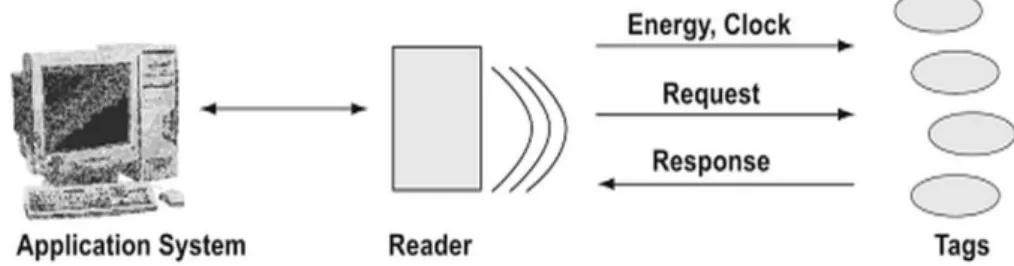
As Figure 2 shows, a complete RFID system consists of three major components in general: a transponder (RF tag or label) with data memory, a reader with antenna and a host with appropriate application which is applied to process data. The operation principle of RFID is shown in Figure 2 and illustrated as follows: (1) data are stored in tiny electronic microchips of transponders, which are
embedded in or labeled on the desired objects; (2) communication between the transponder and a reader is by radio or electromagnetic waves; (3) when the transponders pass through an electromagnetic zone, the reader transmits radio wave energy with center frequency to the transponders, which is called a reader activation signal; (4) the signal actives the transponders to send data to the reader; (5) the reader receives the decodes data; (6) decode data are then transmitted to the computer system for processing.
There are four typical frequency ranges that RFID systems run: LF (low frequency) ranging from 125 kHz to 134.2 kHz, HF (high frequency) operating at 13.56 MHz, UHF (ultra-high frequency) ranging from 860MHz to 960 MHz, and microwave frequency starting from 3.1 GHz and up to around 10 GHz. /4/
Figure 2. RFID System Overview /4/
2.1.2 The Differences between RFID and NFC
According to the RFID frequency bands, the data transfer distance from the RF tag to the reader is ranges from 10cm to 200m. NFC, which is based on the RFID theory, is a new version of RFID. Typically, it is used in an extreme short distance to transfer data. NFC has something in common with RFID, while there are also differences. The comparison is indicated as follows. /5/
Similarity
the radio frequency of frequency spectrum to deliver information. /6/
Both of NFC and RFID operate at the 13.56MHz frequency.
Differences /7/
Since NFC only operates at 13.56MHz frequency and RFID operates distance range from 125 kHz to 10GHz, NFC is a short range (up to 4 inches/10cm) communication technology, while RFID tags can be scanned from a greater distance of up to 300 feet (100 meters).
NFC is capable of two way communication, whereas RFID is a one way communication technology.
NFC can act as both a tag reader and tag writer, this important character allows it to proceeds peer-to-peer (P2P) communication.
Multiple RFID tags can be scanned by one reader device at once, but only one NFC tag at a time.2.1.3 NFC Operating Modes
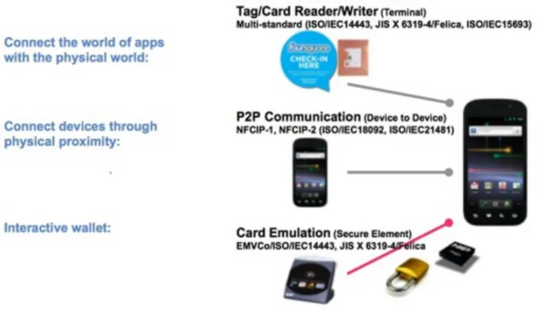
NFC-enabled devices can support three operating modes as Figure 3 shows: reader/writer mode, peer-to-peer mode and card emulation mode. The NFC Forum technical specifications unlock the full capabilities of NFC technology for the different operating modes and are based on the ISO/IEC 18092 NFC IP-1, JIS X 6319-4 and ISO/IEC 14443 contactless smart card standards (referred to as NFC-A, NFC-B and NFC-F in NFC Forum specifications). /1/ In this case we selected reader/writer mode to implement the project.
Figure 3 NFC Operating Mode /1/
Reader/Writer Mode
Reader/Writer mode enable NFC-enabled device is able to exchange data with NFC Forum-mandated tags, such as a tag embedded in a NFC smart poster. It means that in the reader/writer mode, when a NFC tag is put close enough to a NFC device, the device can read data from the tag as well as store data into the tag. The reader/writer mode on the RF interface conforms to the ISO 1443 and FeliCa schemes. /1/
Peer-to-Peer Mode
In the Peer-to-peer mode, two NFC devices are able to communicate with each other to exchange data and share files, so that users of NFC devices can exchange information promptly. For example, users can realize music download, share Bluetooth or WiFi set up parameters or exchange data such as digital photos, videos or phone address book. The Peer-to-Peer mode is standardized on the ISO/IEC 18092 standard. /1/
Card Emulation Mode
The card emulation mode treats NFC devices as smart cards, allowing users to perform transactions such as credit card or bus card. With just a single
touch the function of purchases, ticketing, and transit access control can be fully achieved. An external reader is required when the NFC device acts like a traditional contactless smart card. /1/
The card emulation mode enables ticketing and contactless payments by the NFC-enabled devices without changing existing infrastructure. /1/
2.1.4 Operating Principle of NFC Reader/Writer Mode
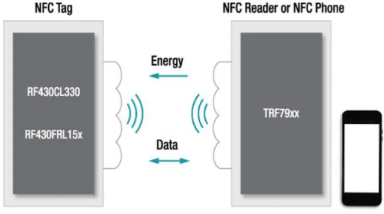
Since we selected the reader/writer mode to implement this project, so in this section, the details of how the reader/writer mode works are explained. When a NFC application starts to work, the reader phone generates a RF sine wave to release energy to the tag and retrieve data from the tag. The sine wave is transmitted at 13.56MHz frequency and it will form an area of magnetic flux.If there is any tag close to the magnetic flux area, the tag will get energy from it and then generate a counter frequency, which can modify the frequency properties of the original sine wave created by phone. After the phone detects the modification it confirms that there is a tag nearby. With the target tag lock-in, data will be transferred between the phone and the tag respectively by the radio wave. Figure 4 shows the general idea of the operating principle of the reader/writer mode.
2.2 NFC Tag
This section gives basic ideas of NFC tag at first, and then introduces the NFC tag type.
2.2.1 NFC Tag Basics
NFC tags, sometimes referred to as smart tags, are embedded chips with little aerials that can go in just about anything and transfer the data or instructions on them via NFC. /9/ It is known as a small memory device, like a USB sticker or wristband, and has its own storage structure and tag type. There are no batteries in the NFC tags, they draw power from a nearby active NFC device or other smartphone.
NFC Forum defined 4 types, from type 1 to type 4. We can store different data types on a NFC tag, such as a URL (Uniform Resource Locator) which goes to a webpage or to an application, contact info, phone number, or even commands and settings that the reading device could execute upon contact. The capacities of a tags depend on the tag type and its configuration, different tag type have different memory capacities. The minimum capacity of one NFC tag is 48bytes, and the maximum of current day is about 8 kB. Besides, NFC tags are affordable and achievable in daily life since it can be bought in Ebay or Amazon. /1/;/10/
In order to set up communication with the active NFC reader/writer, the passive NFC tag was defined. The NFC forum introduced their first standardized technology architecture and standards for NFC compliant devices in June 2006. This included the NDEF (NFC Data Exchange Format), and RTD (Record Type Definitions). /11/ The following section in Chapter 2 introduces NDEF and RTD in details.
2.2.2 NFC Tag Type
According to the NFC forum, there are four basic tag types that have been defined. The different NFC tag type definitions are as follows: /11/
Type 1
Type 1 Tag is based on ISO/IEC 14443A. Tags are read and re-write capable; users can configure the tag to become read-only. Memory availability is 96 bytes and expandable to 2 Kbyte.
Type 2
Type 2 Tag is based on ISO/IEC 14443A. Tags are read and re-write capable; users can configure the tag to become read-only. Memory availability is 48 bytes and expandable to 2 Kbyte.
Type 3
Type 3 Tag is based on the Japanese Industrial Standard (JIS) X 6319-4, also known as FeliCa. Tags are pre-configured at manufacture to be either read and re-writable, or read-only. Memory availability is variable, theoretical memory limit is 1MByte per service.
Type 4
Type 4 Tag is fully compatible with the ISO/IEC 14443 standard series. Tags are pre-configured at manufacture to be either read and re-writable, or read-only. The memory availability is variable, up to 32 Kbytes per service; the communication interface is either Type A or Type B compliant.
ISO/IEC 14443 Type A based on the ISO/IEC 14443 standards. NFC devices implement native support for ISO14443-A tags. The NFC Forum refers to theses
tag as Type 1, Type 2 and Type 4. /11/
2.3 NFC Data Exchange Format
NDEF is a lightweight, binary message format that can be used to encapsulate one or more application-defined payloads of arbitrary type and size into a single message construct. The NDEF specification defines a message encapsulation format to exchange information. Since Android has the most support for the NDEF format, which is defined by the NFC forum, and it is the most universal exchange data format when transferring data via NFC technology, besides it is highly recommend by the Android developer office website, so we utilized the NDEF format to implement data exchange between NFC tags and an Android device in this project. /1/; /12/
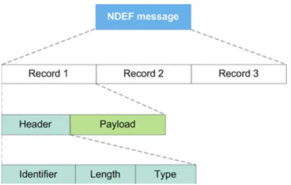
As shown in Figure 5, an NDEF message is composed of numerous records.The record amount in an NDEF message depends on the tag type and calling application. As for this project, only one NDEF record was used to store the verify link. Each NDEF record contains a header and a payload, the payload is described by type, length and an optional identifier encoded in an NDEF record header structure. The payload can be of one of a variety of different types: text, URL, MIME (Multipurpose Internet Mail Extensions) media, or NFC-specific data type. For NFC-specific data types the payload contents must be defined in a NFC Record Type Definition file, RTD.
2.4 Record Type Definition
As described in Section 2.2.3, the data type used in the payload of NDEF record is defined by the NFC forum on the Record Type Definitions (RTDs) technical specification in advance.
The format and rules built for standard record types are specified by the RTD specification in the NFC Forum.This specification provides a way to efficiently define record format for a new application and allows users to create their own applications based on the NFC Forum specification. Five specific RTDs (text, URI (Uniform Resource Identifiers), smart poster, generic control and signature) are used to build standard record types. RTDs have their own mapping object in the Android intent filter, which explained in the later section. /13/
Since we needed to transfer a specified link to the NFC tag, in this project we applied the URI format to define the data type. The URI RTD technical specification defined in the NFC forum provides an efficient way to store URI by using the RTD mechanism and NDEF format.
2.5 How NFC Tags Are Mapped To URI Type
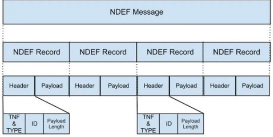
In this section we combine NDEF and RTD together to describe how NFC tags are mapped to the URI type. As we explained in the previous section, data is stored in the NFC tag via the NDEF format, and the data type is defined by the RTD. More specifically, NDEF record is encapsulated inside a message that contains one or more records. Each NDEF record must be well-formed according to the specification of the type of record that we want to create. The structure of NDEF message and NDEF record is shown as Figure 6.
Next comes to how Android handles NDEF formatted tags. When an Android device scans a NFC tag containing NDEF formatted data, it parses the message
and tries to figure out the data’s Multipurpose Internet Mail Extensions (MIME) type or identifying URI. To do this, the system reads the first NdefRcord inside
the NdefMessage to determine how to interpret the entire NDEF message (an
NDEF message can have multiple NDEF records). In a well-formed NDEF message, the first NDEF record contains the following fields: /12/
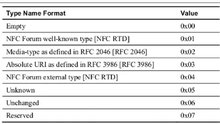
3-bit TNF (Type Name Format)
The 3-bit TNF describes the type of the record. The field value of TNF is show in Table 1. To implement the project, TNF_WELL_KOWN, the NFC Forum well-known type was selected to define RTD_URI, so that the transfer data can be stored as a link in NDEF format.
Table 1 TNF Field Value /12/
TYPE_LENGTH
The TYPE_LENGTH field is an unsigned 8-bit integer that specifies the length in octets of the TYPE field. The TYPE_LENGTH field is always zero for certain values of the TNF field
ID_LENGTH
in octets of the ID field. This field is present only if the IL flag is set to 1 in the record header. An ID_LENGTH of zero octets is allowed and, in such cases, the ID field is omitted from the NDEF record.
PAYLOAD_LENGTH
The PAYLOAD_LENGTH field is an unsigned integer that specifies the length in octets of the payload field. The size of the PAYLOAD_LENGTH field is determined by the value of the SR (Short Record) flag. If the SR flag is set, the PAYLOAD_LENGTH field is a single octet representing an 8-bit unsigned integer. If the SR flag is clear, the PAYLOAD_LENGTH field is four octets representing a 32-bit unsigned integer.
Figure 6 Structure of NDEF Message and NDEF Record /1/
2.6 Android Basics in NFC Development
This project was implemented through the Android OS (Operating System) on account of its widely used, powerful portability and operation flexibility. Moreover, since 2010 the first Android NFC phone Samsung Nexus S has been published, nowadays the majority of Android-based devices support the NFC functionality, therefore, we exploited Android OS as a development platform. /14/
Here we introduce some vital concepts of Android basics in NFC development before we start programming.
2.6.1 Android Activity
An activity is an application component in the Android OS, it can provide a screen with which users can interact in order to do something, such as dial the phone, take a photo, send an email, or view a map. It is one of the most important components in the Android system. Each activity is given a window in which to draw its user interface. The window typically fills the screen, but may be smaller than the screen and float on top of other windows. /15/
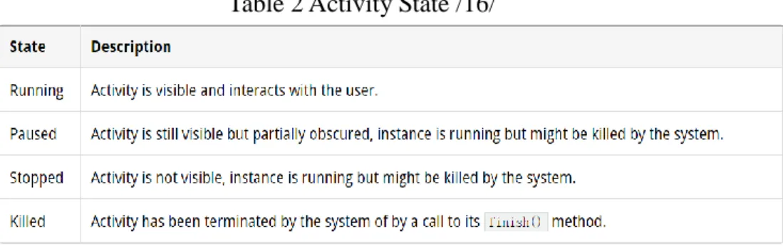
There are four states on an activity when it is interacting with the user. Table 2 describes these states.
Table 2 Activity State /16/
From created to destroy, an Android Activity has a lifecylce during which it performs a few things.
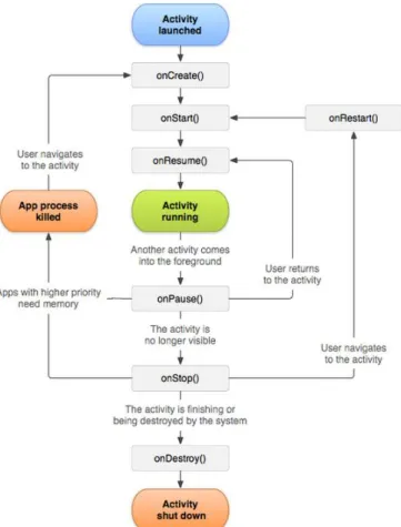
An activity contains seven callback methods during its lifecycle, which are onCreate(), onStart(), onResume(), onPause(), onRestart(), onStop(), onPause(), and onDestroy().
Figure 7 shows the important stat paths of an Activity. The square rectanges represent callback methods that can be implemented to perform operations when the Activity moves between the states. The colored ovals are the major state the
Activity can be in. /15/
Figure 7 The Activity Lifecycle /15/
Among these predefined lifecycle methods, the most important methods are illustrated in Table 3. /16/
2.6.2 Intent and Intent-Filter
Intents are asynchronous messages which allow application components to request functionality from other Android components. Intents allow user to interact with components from the same applications as well as with components contributed by other applications. For example, an activity can start an external activity for taking a picture. /17/
An intent filter declares the capabilities of its parent component – what an activity or service can do and what types of broadcasts a receiver can handle. It opens the component to receiving intents of the advertised type, while filtering out those that are not meaningful for the component. /18/
Intents are divided into two types, explicit type and implicit type. With an explicit intent to start service or an activity, the application components specified in the Intent object will be immediately started by the system. While with an implicit intent, the Android system finds the appropriate component to start by comparing the contents of the intent to the intent filters declared in the manifest file of other applications on the device. If there is any intent that matches an intent filter, the system starts that component and delivers the intent object to it. If multiple intent filters are compatible, the system displays a dialog so the user can pick which app to use. More generally, for the convenience of testing the application, an explicit intent will be chosen to implement the development. /19/
2.6.3 How NFC Tags Are Dispatched to Application
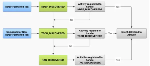
After data has already been stored in the NFC tag, there will be a tag dispatch system (will be described in Chapter 3) to create an intent to encapsulates the tag and its carry data. Then the system sends the encapsulated intent to an interested application that filters for the intent. The tag dispatch system defines three
intents, which are stored in priority. The structure can be seen in Figure 8. /20/
1. ACTION_NDEF_DISCOVERED: This intent is used to start an Activity when a tag that contains an NDEF payload is scanned and is of a recognized type. This is the highest priority intent, and the tag dispatch system tries to start an Activity with this intent before any other intent, whenever possible.
2. ACTION_TECH_DISCOVERED: If no activities registered to handle the
ACTION_NDEF_DISCOVERED intent, the tag dispatch system tries to start an application with this intent. This intent is also directly started (without starting ACTION_NDEF_DISCOVERED first) if the NDEF data contains in the tag cannot be mapped to MIME type or URIor if the tag does not contain NDEF data but is of a known tag technology.
Actually this kind of intent can define a more accurate data type by setting up an XML file to filter the suitable data, so in this case the ACTION_TECH_DISCOVERED was used to encapsulate NFC tag.
3. ACTION_TAG_DISCOVERED: This intent is started if no activities
handle the ACTION_NDEF_DISCOVERED or
ACTION_TECH_DISCOVERED intents.
3
IMPLEMENTATION
Chapter 3 comprehensively introduces the implementation of the entire project, which includes the development environment, supportive theory, implement procedure and flowchart of each module.
3.1 Development Environment
To implement this application, specified hardware and software were required. In this section, the configuration of the development environment, all the implementation tools and the languages are described.
3.1.1 JDK Configuration
The Android application program is coded in JAVA and hence a JDK (Java Developer’s Kit) needs to be installed, also related environment variables needs to be configured. How to configure JDK in computer is demonstrated step by step as follows.
1. JDK Set Up
The JDK package was downloaded from ORACLE’s official website
http://www.oracle.com/technetwork/articles/Javase/index-jsp-138363.html
and installed on the computer. The path of JDK installation directory needed
to be remembered, in this case the path was
C:\ProgramFiels\Java\jdk1.7.0_45\
2. Setting Path and Class path for Java
The “Control Panel\System and Security\System” was opened and the “Advanced system settings” was found, “Environment Variables” was clicked in the System Properties window to set the path. Figure 9 is the
screenshot of the procedure.
Figure 9 Environment Variables Setting
A new variable “PATH” was created in the “System Variables” window if there does not exist one. Here we needed to fill the JDK’s bin directory path, which was under its installation directory. The setting of new system variable is shown in Figure 10.
A new variable “CLASS” was created in the “User variables” window and filled the JDK’s lib directory as Java’s class path like Figure 11 shows.
Figure 11 Java Class Path Setting
3. Verifying Configuration
After all the variable settings were accomplished, we opened the cmd.exe to verify JDK configuration status. With the command “Java” and “Javac” we could specify whether the configuration was complete or not. Here we used “Java –version” to check the installed JDK’s version. The result is shown in
Figure 12.
3.1.2 Configuration of Android Developing
After Java configuration, we downloaded and installed the Android Software Development Kit (SDK), then set up Android Development Tools (ADT) on Eclipse, and then installed the corresponding smartphone driver.
Before we started to configure SDK or ADT, we needed to ensure that Eclipse was installed.
Android SDK Configuration
1. Download the SDK Starter Package
Firstly we downloaded the SDK starter package from its website:
https://developer.android.com/sdk/index.html, then with the extract package we could install the release directory into our designated location. After that we ran the SDK setup.exe, and through the instructions of its prompt window we could successfully install it.
2. Available Package
By running the setup.exe, an Android SDK Manage window showed up as Figure 13. “Available Package” was clicked and the packages were download and its related document or other packages that we intended to use. As for this project, we downloaded all the available packages.
Figure 13 Android SDK Manager
ADT Configuration
1. Download the ADT Plugin
As Figure 14 shows, we launched Eclipse at first, and then selected “Install New Software” in the Help menu, clicked “Add” button, an “Add Repository” dialog would appear on the screen, “ADT Plugin” was entered for the Name and https://dl-ssl.google.com/android/eclipse/ for the “Location”. “OK” was clicked and then related developer tools were selected in the Available Software dialog.
Figure 14 Download the ADT Plugin
2. Configure the ADT Plugin
To restart Eclipse, there was a “Welcome to Android Development” window, we selected the “Using existing SDK” button and specified the location of the Android SDK directory that we had already downloaded beforehand. The screenshot is shown in Figure 15.
As Figure 16 shows, with the complete configuration of Android SDK and ADT, now Eclipse was able to handle Android application, we could create a new Android project to start our application.
Figure 16 New Android Project
3.1.3 Development Tools
In this section a list of the development tools used in this project is given.
Hardware
1. PC(Laptop)
Product Model: Dell Ins14VR-368
Operating System: Win 7
2. NFC-enabled phone
Product Model: Samsung Galaxy S4 GT-19502
3. NFC tag
Type A(ISO/IEC 14443 Type A)
Tag Type: NFC Forum Type 2 Tag
Capacity: 142 Byte
Is tag writeable: yes
Bought from eBay /21/, the tag using in this project is shown as Figure 17.
Figure 17 NFC Tag
4. Micro USB cable
Connecting development phone and laptop
Software:
1. Eclipse 4.3
Execution environment: JDK, Android SDK, ADT 23.0.4
Development purpose: implement NFC reader application and writer application
2. Notepad++ V6.6.7
Development Language:
1. Java
2. PHP
3.2 Supportive Theory of Implementation
Before we started to develop the project, it was necessary to be familiar with some technical theories which support the implementation process. Here NFC API, NFC foreground dispatch system and NFC dispatch system are described. The detailed usage of these theories will be explained in the following section.
3.2.1 NFC API
The Android system introduces NFC API after API 9. Currently, there are two packages managing the NFC development in Android system, namely
Android.nfc and Android.nfc.tech.
The Android.nfc.tech package provides access to a tag technology’s features, which vary by the type of the tag. The technology’s features of NFC tags include its independently developed technologies specification (for example ISO 14443-3A or ISO 14443-3B) and its related capabilities (for example Ndef, NdefFormatable). /22/
While the Android.nfc package is mainly used to provide access to NFC functionality, allowing applications to read NDEF message in NFC tags. /23/
Here two main classes we used in this project are introduced: /23/
NdefMessage
Represents an NDEF data message, which is the standard format in which “records” carrying data are transmitted between devices and tags.
The application can receive these messages from an ACTION_TAG_DISCOVEREND intent.
NdefRecord
Represents a record, which is delivered in a NdefMessage and describes the type of data being shared and carries the data itself.
3.2.2 NFC Foreground Dispatch System
The NFC foreground dispatch system is a technology used in the active program (foreground running activity) to handle tag. It allows an activity to intercept intent and claim priority over other activities that handle the same intent. It is quite easy and convenient to obtain an NFC message in the foreground activity by using this system. The foreground dispatch system involves constructing a few data structures for the Android system so that it can send the appropriate intents to the dedicated application. /24/
3.2.3 NFC Tag Dispatch System
The NFC dispatch system is a sort of mechanism that launches application program through a pre-defined tag or NDEF message. An application that wants to handle the scanned NFC tag can declare an intent filter and request to handle the data. That is, when scanning a NFC tag, if the related application has already been registered in the Intent-Filter, then the application would be automatically called to handle the discovered tag. To summarize, the tag dispatch system is able to analyze scanned tags, parses them, and tries to locate applications that are interested in the scanned data. It does this by /20/:
Parsing the target NFC tag and figuring out the MIME type or a URI that identifies the data payload in the tag.
Encapsulating the MIME type or URI and the payload into an intent.
Starting an appreciate activity based on the intent.
To explain it, when an Android-powered device scans an NFC tag containing NDEF formatted data, it parses the message and tries to figure out the data’s MIME type or identifying URI. To do this, the system reads the first NdefRecord
inside the NdefMessage to determine how to interpret the entire NDEF message (an NDEF message can have multiple NDEF records). In a well-formed NDEF message, the first NdefRecord contains TNF, type, ID and payload. /20/
The tag dispatch system uses the TNF and type fields to try to map a MIME type or URI to the NDEF message. If successful, it encapsulates that information inside of ACTION_NDEF_DISCOVERED intent along with the actual payload. However, there are cases when the tag dispatch system cannot determine the type of data based on the first NDEF record. This happens when the NDEF data cannot be mapped to a MIME type or URI, or when the NFC tag does not contain NDEF data to begin with. In such cases, a Tag object that has information about the tag’s technologies and the payload are encapsulated inside of ACTION_TECH_DISCOVERED intent instead. /20/
The basic way the tag dispatch system works is as follows: /20/
1. Try to start an Activity with the intent that was created by the tag dispatch system when parsing the NFC tag (either ACTION_NDEF_DISCOVERED or ACTION_TECH_DISCOVERED)
2. If no activity filters is set for that intent, try to start an Activity with the next lowest priority intent (either ACTION_TECH_DISCOVERED or ACTION_TAG_DISCOVERRED) until an application filter for the intent or until the tag dispatch system tries all possible intents.
3. If no applications filter for any of the intent, do nothing.
3.3 Development Procedure
The project is divided into three modules: writing the NFC tag module, scanning the NFC tag module, and the PHP service module. Figure 18 demonstrates the flow diagram of the entire project. For this project, the tag writer and reader application can be installed in the same phone. To achieve the write tag data or read tag data function, we started the correspondent application at first, and then put the NFC tag close to the Android-based phone to transfer data, lastly checked the received feedback from the application. During the read/write data process, a decision process was found to decide whether the data transmission process was successful or not. If the transfer procedure failed, the application returned a notice message to remind the user. Otherwise the received data would be taken up by the PHP server. If writing data successfully, a successful prompt message would be turned back to the user.
The procedure about how to implement this project will be introduced step by step in the following section.
3.3.1 Before Programming
Before we started to program, several steps needed to be done in advance to ensure the development process work well.
1. Enable the NFC function available in the develop phone. We could check it in the setting system as shown in Figure 19.
Figure 19 NFC Function Enable
2. Open the NFC function and developer options in the setting system as Figure 20 shows, then click “USB debugging” and “Allow mock locations”.
3.3.2 Requesting NFC Access in the Android Manifest
In order to get access to phone’s NFC hardware and cope with NFC intents properly, we needed to declare the permission of NFC function in the Android project’s AndroidManifest.xml file at first:
Declared the permission of NFC hardware in the <user-permission> element.
Defined the minimum SDK version that support the develop application. Generally, API level 9 and upwards level support NFC function, among them API level 10 contains comprehensive reader/writer support as well as foreground NDEF pushing. In this project, the minimum SDK version was 10, while the target SDK version is the newest version 21. /20/
Enabled the APK only available for the NFC-enabled phone by defining the uses-feature element.
3.3.3 Filtering for NFC Intents
As Section 3.2.3 describes, in order to start application when a target NFC tag is scanned, we can filter one, two, or all three of the NFC intents in the
AndroidManifest.xml file. Here we defined ACTION_TECH_DISCOVERED intent in the AndroidManifest.xml to locate the scanned tag. This intent is able to achieve the NFC intent more accurately and expediently, as well as to ensure our application can be called by the system successfully. Meanwhile, an
nfc_tech_filter.xml file needed to be created in the res/xml folder to specify the technologies that the activity supports within a tech-list set. If the tech-list set is a subset of the scanned tag’s supportive technologies, the activity is able to match and handle the discovered tag. To summarize, we needed to complete the following steps:
Declare ACTION_TECH_DISCOVERED intent
Define activity supportive technologies
In this case only tech.MifareClassic technology was being defined, and if this technology is a subset of the scanned tag’s supportive technologies, then the activity is considered as a match of the tag, and the technologies can be called through getTechList().
3.3.4 NFC Foreground Dispatch System Implementation
With the foreground dispatch system we can easily obtain and push NDEF message in the foreground running activity. Here we need to implement foreground dispatch system in both reader and writer application to help us handle the target tag and the NFC message. To enable the foreground dispatch system we needed to go through with the following steps. /23/
Create a PendingIntent object in the onCreate() method to encapsulate data so that the Android system can populate it with the details of the data when it is scanned.
Declare intent filters to intercept ACTION_TECH_DISCOVERED intent
Set up an array of tag technologies mTechList to obtain scanned tag’s technology features, in this case NfcA class in Android.nfc.tech package was used to provide access to NFC-A (ISO 14443-3A) properties and I/O operations on the detected tag. Here we called the Object.class.getName()
method to obtain the class of desire technology.
Overwrite the onPause(), onResume(), onNewIntent() method to enable the foreground dispatch system can be properly called and suspended in the activity.
protected void onResume() { super.onResume();
mNfcAdapter.enableForegroundDispatch(this, pendingIntent,mWriteTagFilters, mTechLists);
}
protected void onPause() { super.onPause();
disableForegroundDispatch(); }
protected void onNewIntent(Intent intent) {
// do something with tag from the intent }
When an activity regained, we enabled the foreground dispatch system in the
onResume() method. enableForgroundDispatch() must be called from the main thread and only when the activity is in the foreground (calling
enableForgroundDispath() in onResume() will guarantees this). When an activity lost, we disabled the system in the onPause() method. The
onNewIntent() method was used to handle the writing data into detected tag function or reading data from the scanned tag function.
As for the details of how we implemented the writing data and reading data function, Section 3.3.5 and Section 3.3.6 will introduce the operation steps specifically.
3.3.5 NFC Tag Write Operation Steps
When the NFC application program detected a NFC tag, it would start the activity which was defined in the AndroidManifest.xml. User can do what he/she wants to do in the activity. If we want to write specific data into a NFC tag, there are three operation steps we should follow:
2. Prepare NDEF data , transfer the specific data into NDEF format
3. Write NDEF data into the detected tag
For the first step, we can obtain a tag object by getting it from the Intent, while Intent involves the related information about the target tag. The tag object is encapsulated in the target tag. As for the other two steps, the communication data used in the NFC technology should be transferred into the NDEF format data in a uniform way in step 2. Step 3 fulfills the process of writing NDEF data into the NFC tag. The two later steps will be explained as follows in details.
Acquire transitive data
To authenticate a product, we can verify its product ID and unique SN, while SN is based on ID and generated via specific algorithm. With a custom algorithm or an encryption and related decryption algorithm only one SN can be determined. Since the algorithm is mastered by the developer so that nobody can obtain the correct decipherment algorithm, this ensures the security of the authentication procedure. Only by using the correct algorithm can we get the correct and matched SN. Therefore, we implemented the related decipherment algorithm on the verify.php to validate the product’s ID and SN.
Here we selected Base64 encoding schemes to encode the ID and then get its sole SN. Actually if we want to ensure the security of the authentication issue another encrypt algorithm should be applied in here. The formula is shown in this way: SN = f(x), while x = ID and f =selected encrypt algorithm. ID can be created through a random function. The source code of this procedure is shown as below:
Random random = new Random();
Long ID = random.nextLong();// get a random value as ID ID = Math.abs(id); //get id’s absolute value
String idString = String.valueOf(id);
String SN = encodeStr(idString); // get ID’s related SN
//encodeStr() is a method that implement encryption algorithm
In this project the validation file verify.php was configured in the VAMK’s official website http://www.cc.puv.fi to verify received ID and SN. The entire link can be shown in this way:
http://www.cc.puv.fi/~e1001920/verify.php?id=xxx&sn=xxx.
Acquire NDEF Message
Before we wrote data into an NFC tag, we needed to convert the data into the NDEF record on the basic of NFC Forum definition. As Section 2.5 describes, in here TNF_WELL_KNOWN was used to define specific RTD to transfer data. Since the data here is a link (URI), so according to the official recommendation we selected RTD_URI record type to create NDEF record. The following code specified the way of using RTD_URI way to obtain efficient NdefRecord object. /20/
String url = "http://www.cc.puv.fi/~e1001920/verify.php?id="+idString+"&sn="+sn; NdefRecord rtdRecord = NdefRecord.createUri(url);
Then the rtdRecord should be encapsulated into an NDEF message object and return to the original function.
return new NdefMessage(new NdefRecord[] { rtdRecord });
So far, NDEF message object NdefMessage has been generated.
Writing NDEF Message into NFC tag
After the link had been transfer into NdefMessage, we could continue to write it into NFC tag. By encapsulating a utility method writeTag() to focus on the
writing procedure, we could easily fulfill the writing data operation. The
writeTag() method requires two parameters, one is a complete NdefMessage and the other one is an Tag object. The main code of this method is as follows:
boolean writeTag(NdefMessage message, Tag tag){
int size = message.toByteArray().length;//get the NFC tag’s memory size Ndef ndef = Ndef.get(tag); // Detected NFC tag and get its //object if (ndef != null) {
ndef.connect(); //connection establishment if (!ndef.isWritable()) {
toast("Error:Tag can not be write");
return false;
} //decide whether the scanned tag is writable or not if (ndef.getMaxSize() < size) {
toast("Error:Data payload is overflow. ");
return false;
}
// data cannot be write into the tag if its size is over the tag memory size ndef.writeNdefMessage(message);
toast("write successful!"); ndef.close(); //connection close
return true;
else{…} } }
3.3.6 NFC Tag Read Operation Steps
In general, reading tag operation includes three main steps as below:
1. Define Tag object to obtain scanned tag’s intent
3. Parse NDEF message to get the raw data
After the three steps we can utilize the raw data to conduct further operation.
Step 1 is about how to get the tag object from the intent, while step 2 receives the NDEF message from the intent and parses it in step 3. Here we briefly explain the latter two steps.
Receive NDEF Message
We can get the NDEF message (NdefMessage) from the scanned tag’s intent, which is written by the Tag writer application. To implement the procedure we defined a resolveIntent() method to deal with the received intent. The main code of the method is as follows:
private void resolveIntent(Intent intent) { String action = intent.getAction();
if (mNfcAdapter.ACTION_TECH_DISCOVERED.equals(action)) { NdefMessage[] messages = null; //defined NdefMessage Object Parcelable[] rawMsgs =
intent.getParcelableArrayExtra(mNfcAdapter.EXTRA_NDEF_MESSAGES); // Received Tag’s information and put it in a Parcelable[] arrary
if (rawMsgs != null) {
messages = new NdefMessage[rawMsgs.length]; for (int i = 0; i < rawMsgs.length; i++) {
messages[i] = (NdefMessage) rawMsgs[i];
// Received NDEF message from Parcelable arrary and cast it into a NdefMessage object
} }else {…….}
Parse NDEF Message
In this step we parse the received NDEF message to get the original data. As described in the background chapter, the NDEF message is composed of a sequence of records, and each record contains a payload and a header. The header is composed of TNF, ID and payload length. Before parsing the NDEF message we should know the payload type of the record, the TNF, in this case the payload type is URI and there is only one record within the NdefMessage. We implemented a parseNdefMessage() and called it in the resolveIntent()
method when the NdefMessage had been dispatch from the intent. Here is the main code in the parseNdefMessage():
private void processNDEFMessage(NdefMessage[] messages) { if (messages == null||messages.length == 0 ) {
toast("NdefMessage is null.");
// check whether NdefMessage is null string or not
}
for (int i = 0; i < messages.length; i++) {
int length = messages[i].getRecords().length; NdefRecord[] records = messages[i].getRecords(); byte[] payload = records[0].getPayload();
//there is only one record in the NdefMessage in this case
for (int j = 0; j < length; j++) {
for (NdefRecord record : records) { if (isUri(record)) {
byte[] payload = record.getPayload();
String prefix =URI_PREFIX_MAP.get(payload[0]); byte[] fullUri =
Bytes.concat(prefix.getBytes(Charset.forName("US-ASCII")), Arrays.copyOfRange(payload,1, payload.length));
Uri uri = Uri.parse(new
String(fullUri,Charset.forName("US-ASCII")));
// parse the byte of uri into Uri object, then the data encapsulated in tag //can be obtained
//doing something here…. }}}}}
The authentication of the product
Now we achieved the encapsulated data from the tag, which is a well-formed
link from the NFC tag, just like
http://www.cc.puv.fi/~e1001920/verify.php?id=xxx&sn=xxx. Next we went to the PHP server side through this URI for further information. With the received URI the phone’s browser would automatically go into the verfy.php page and display the verified result. We implemented this procedure by start a new activity.
Intent intent = new Intent(Intent.ACTION_VIEW,uri); startActivity(intent);
After the new activity started the application redirected to the PHP server side, the product’s ID and SN would be handed over by verify.php.
3.3.7 PHP Server Implementation
Finally we come to the PHP server implementation. Here we used the decipherment algorithm to check whether the SN match the ID or not, which means if ID = decodeBase64(sn) was correct. Then it proves that the ID and SN belong to quality goods, otherwise the wrong SN indicates that it is a counterfeit. The verification result will be given back to the user on the browser. The main body of the verify.php is shown below:
function match($id, $sn){
// define a function to decode Base64 $idStr=base64_encode($id);
$snStr=base64_decode($sn); if(($idStr==$sn)&&($snStr==$id)){ return true;
}
else return false; } // end of function
3.4 Flowchart of the Program
Owing to the situation that this project is divided into three parts, or in other words three modules, writing tag module, read tag module and PHP verify module, so we implemented the three modes respectively. The writing tag project and reading tag project were implemented by using the complete Android activity lifecycle method. This section illustrates the workflow of the three modules with them separate flowchart.
3.4.1 Writing Tag Module Flowchart
As we can see from Figure 21, when the application begins, onCreate() method initialize the UI and defined variables, after the UI initialization if the user wants to write data into an NFC tag, the application will try to detect if the NFC tag exists nearby or not. If the tag is being scanned successfully, the application will call the method to gain NdefMessage and then write it into tag, otherwise it will turn back to detect the tag again. As long as the data is written into the tag successfully, the writer application will feed back a prompt message to the user, and then the application is finished. Or if there is something wrong during the writing data procedure, the user will receive an error message, and then the application will try to write NdefMessage into the tag again. The details about how to implement the writing tag procedure can be checked in the implementation procedure in Section 3.3.5.
Figure 21 Writing Module Flowchart
3.4.2 Reading Tag Module Flowchart
As Figure 22 shows, in the reading tag module, firstly we need to start the application, build up the UI and detected the NFC tag, which are almost the same as writing module’s initial work. However, as for the reader tag application, we intercept the detected tag’s intent, get its internal NdefMessage and then try to parse it. If NdefMessage in the NFC tag is being parsed correctlythen it will be processed by PHP server. A verify.php file running on the server side will handle the receive data and give related feedback to the users, finally the reader application is end. Or it will return an error message to the user and the application ends as well.
Figure 22 Reading Tag Module Flowchart
3.4.3 PHP Server Flowchart
As for the PHP server side shown in Figure 23, it receives ID and SN from the reader application, and decodes the SN according to the specific algorithm. If the verified SN can match the received ID as well as ID can deduce unique SN, then both the ID and SN are correct, which means the carry-in data of the product is valid, and it is a quality product. While if ID and SN cannot match each other, then the product is counterfeit.
4
TEST AND RESULT
With supportive technical principles, methods and implementation, the project was successfully accomplished. In this chapter the way of testing the application and its result will be demonstrated in details.
4.1 Functional Test
In this section, a sequence of measurement was applied to test performance of the two applications.
4.1.1 Writing Tag Application Test
We started the writing tag application at first. The UI of the application is shown in Figure 24.
Figure 24 Writing Tag Application UI
There is only one button in the UI. We clicked the Tag Generate button to write data into an NFC tag. A window appeared in the middle of the application to remind us putting the NFC tag close to the phone. The prompt window can be checked in Figure 25. Usually the tag should be put on the
back of the phone, in its inductor position. The distance of it should keep within1cm or less, otherwise the phone cannot detect the nearby NFC tag. Although the ideal transmit distance of NFC transmission is up to 10 cm, however, due to the fact that the small tag and phone generally have far less range, so in order to achieve a better contact from the phone to the tag, in this case we try to connect the phone and the NFC tag as near as possible.
Figure 25 Prompt Window Of Writting Application
If the writing data operation is successful, a prompt message will be given to the user to express as Figure 26 shows.
If there something wrong happened with the writing process, such as no tag is detected or the connect distance is not short enough, the application will also give an error message to the user and allow them to try to detect tag again until the writing process is successful. The error prompt message is shown in Figure 27.
Figure 27 Error Prompt Message
4.1.2 Reading Tag Application Test
Firstly, we started the reading tag application as Figure 28 shows. It is much like the write application UI, which also includes a scan button under the welcome message.
Figure 28 Reading Tag Application UI
The scan button has to be clicked when we want to read the tag. A window like Figure 29 will show up in the screen to remind us to put the tag close to the phone.
Figure 29 Prompt Window Of Reading Application
If the reading tag operation works successfully, the link stored in the tag will be received by the phone and then applied to the browser automatically.
Otherwise, an error message will be returned to the user. The further information about the verify result will be manipulated by the verify.php and show on the browser finally.
4.2 Result
Finally the verify result of the product displays on the browser in the phone. On one hand, a quality product with valid product ID and SN can pass the authentication of the PHP verify server, and the correspondent product information will be displayed on the browser as Figure 30 shows.
Figure 30 Quality Product Result
On the other hand, if the product is a counterfeit, which do not have correct SN, then it cannot get through the validation of the PHP Server, and the related notice will be given to users as shown in Figure 31.
4.3 Summary
Since each product has its ID and correspondent SN, the unique SN can be treated as a symbol to decide the authenticity of product. In this case correct ID and SN are given by the specific algorithm. Only by using this algorithm can we obtain the correct ID and SN, so the same algorithm is going to be used on the PHP server side to verifying the authentication of product. In other words, verifying the SN is the same as verifying the counterfeit product and quality product.
For purpose of implementing this project, two Android applications were built to transfer data to and from NFC tag, meanwhile the NFC tag is regarded as transfer medium. Finally we constructed the PHP server to verify the received ID and SN. By defining the specific algorithm and using the NFC technology for transmission the security and reliability of the product authentication issue was ensured.