ETSI TS 126 131
V11.0.0
(2012-10)
Universal Mobile Telecommunications System (UMTS);
LTE;
Terminal acoustic characteristics for telephony;
Requirements
(3GPP TS 26.131 version 11.0.0 Release 11)
Reference
RTS/TSGS-0426131vb00
Keywords
LTE,UMTS
ETSI
650 Route des Lucioles
F-06921 Sophia Antipolis Cedex - FRANCE
Tel.: +33 4 92 94 42 00 Fax: +33 4 93 65 47 16
Siret N° 348 623 562 00017 - NAF 742 C Association à but non lucratif enregistrée à la
Sous-Préfecture de Grasse (06) N° 7803/88
Important notice
Individual copies of the present document can be downloaded from:
http://www.etsi.org
The present document may be made available in more than one electronic version or in print. In any case of existing or perceived difference in contents between such versions, the reference version is the Portable Document Format (PDF). In case of dispute, the reference shall be the printing on ETSI printers of the PDF version kept on a specific network drive
within ETSI Secretariat.
Users of the present document should be aware that the document may be subject to revision or change of status. Information on the current status of this and other ETSI documents is available at
http://portal.etsi.org/tb/status/status.asp
If you find errors in the present document, please send your comment to one of the following services:
http://portal.etsi.org/chaircor/ETSI_support.asp Copyright Notification
No part may be reproduced except as authorized by written permission. The copyright and the foregoing restriction extend to reproduction in all media.
© European Telecommunications Standards Institute 2012. All rights reserved.
DECTTM, PLUGTESTSTM, UMTSTM and the ETSI logo are Trade Marks of ETSI registered for the benefit of its Members.
3GPPTM and LTE™ are Trade Marks of ETSI registered for the benefit of its Members and of the 3GPP Organizational Partners.
Intellectual Property Rights
IPRs essential or potentially essential to the present document may have been declared to ETSI. The information pertaining to these essential IPRs, if any, is publicly available for ETSI members and non-members, and can be found in ETSI SR 000 314: "Intellectual Property Rights (IPRs); Essential, or potentially Essential, IPRs notified to ETSI in
respect of ETSI standards", which is available from the ETSI Secretariat. Latest updates are available on the ETSI Web
server (http://ipr.etsi.org).
Pursuant to the ETSI IPR Policy, no investigation, including IPR searches, has been carried out by ETSI. No guarantee can be given as to the existence of other IPRs not referenced in ETSI SR 000 314 (or the updates on the ETSI Web server) which are, or may be, or may become, essential to the present document.
Foreword
This Technical Specification (TS) has been produced by ETSI 3rd Generation Partnership Project (3GPP).
The present document may refer to technical specifications or reports using their 3GPP identities, UMTS identitiesor GSM identities. These should be interpreted as being references to the corresponding ETSI deliverables.
The cross reference between GSM, UMTS, 3GPP and ETSI identities can be found under http://webapp.etsi.org/key/queryform.asp.
Contents
Intellectual Property Rights ... 2
Foreword ... 2
Foreword ... 5
Introduction ... 5
1 Scope
... 6
2 References
... 6
3 Definitions,
symbols and abbreviations ... 7
3.1 Definitions ... 7
3.2 Abbreviations ... 7
4 Interfaces ... 7
5
Narrowband telephony transmission performance ... 8
5.1 Applicability ... 8
5.2 Overall loss/loudness ratings ... 8
5.2.1 General ... 8
5.2.2 Connections with handset UE ... 9
5.2.3 Connections with desktop and vehicle-mounted hands-free UE... 9
5.2.4 Connections with hand-held hands-free UE ... 9
5.2.5 Connections with headset UE ... 10
5.3 Idle channel noise (handset and headset UE) ... 10
5.3.1 Sending ... 10
5.3.2 Receiving ... 10
5.4 Sensitivity/frequency characteristics ... 11
5.4.1 Handset and headset UE sending ... 11
5.4.2 Handset and headset UE receiving ... 11
5.4.3 Desktop and vehicle-mounted hands-free UE sending ... 12
5.4.4 Desktop and vehicle-mounted hands-free UE receiving ... 13
5.4.5 Hand-held hands-free UE sending ... 14
5.4.6 Hand-held hands-free UE receiving ... 15
5.5 Sidetone characteristics (handset and headset UE) ... 16
5.5.1 Sidetone loss ... 16
5.5.2 Sidetone delay ... 16
5.6 Stability loss ... 16
5.7 Acoustic echo control ... 17
5.7.1 General ... 17
5.7.2 Acoustic echo control in desktop and vehicle-mounted hands-free UE ... 17
5.7.3 Acoustic echo control in hand-held hands-free UE ... 17
5.7.4 Acoustic echo control in a handset UE ... 18
5.7.5 Acoustic echo control in a headset UE ... 18
5.8 Distortion ... 18
5.8.1 Sending distortion ... 18
5.8.2 Receiving ... 19
5.9 Ambient noise rejection ... 19
5.10 Information on other parameters (not normative) ... 21
5.11 Sending performance in the presence of ambient noise ... 21
5.11.1 General ... 21
5.11.2 Connections with handset UE ... 21
5.12 Delay ... 21
5.12.1 Handset UE ... 21
5.12.2 Headset UE ... 21
5.12.2.1 Wired headset ... 21
5.12.2.2 Wireless headset ... 22
5.13.1 Handset ... 23
5.13.2 Headset ... 23
5.13.3 Handheld hands-free ... 23
5.13.4 Desktop and vehicle mounted hands-free ... 23
6 Wideband
telephony
transmission performance ... 23
6.1 Applicability ... 23
6.2 Overall loss/loudness ratings ... 23
6.2.1 General ... 23
6.2.2 Connections with handset UE ... 24
6.2.3 Connections with desktop and vehicle-mounted hands-free UE... 24
6.2.4 Connections with hand-held hands-free UE ... 24
6.2.5 Connections with headset UE ... 25
6.3 Idle channel noise (handset and headset UE) ... 25
6.3.1 Sending ... 25
6.3.2 Receiving ... 25
6.4 Sensitivity/frequency characteristics ... 25
6.4.1 Handset and headset UE sending ... 26
6.4.2 Handset and headset UE receiving ... 26
6.4.3 Desktop and vehicle-mounted hands-free UE sending ... 27
6.4.4 Desktop and vehicle-mounted hands-free UE receiving ... 28
6.4.5 Hand-held hands-free UE sending ... 29
6.4.6 Hand-held hands-free UE receiving ... 30
6.5 Sidetone characteristics (handset and headset UE) ... 32
6.5.1 Sidetone loss ... 32
6.5.2 Sidetone delay ... 32
6.6 Stability loss ... 32
6.7 Acoustic echo control ... 32
6.7.1 General ... 32
6.7.2 Acoustic echo control in desktop and vehicle-mounted hands-free UE ... 33
6.7.3 Acoustic echo control in hand-held hands-free UE ... 33
6.7.4 Acoustic echo control in a handset UE ... 33
6.7.5 Acoustic echo control in a headset UE ... 33
6.8 Distortion ... 34
6.8.1 Sending distortion ... 34
6.8.2 Receiving ... 35
6.9 Ambient noise rejection ... 36
6.10 Sending performance in the presence of ambient noise ... 36
6.10.1 General ... 36
6.10.2 Connections with handset UE ... 36
6.11 Delay ... 36
6.11.1 Handset UE ... 36
6.11.2 Headset UE ... 37
6.11.2.1 Wired headset ... 37
6.11.2.2 Wireless headset ... 37
6.12 Echo control characteristics ... 37
6.12.1 Handset ... 38
6.12.2 Headset ... 38
6.12.3 Handheld hands-free ... 38
6.12.4 Desktop and vehicle mounted hands-free ... 38
Annex A (informative):
Change history ... 39
Foreword
This Technical Specification has been produced by the 3rd Generation Partnership Project (3GPP).
The contents of the present document are subject to continuing work within the TSG and may change following formal TSG approval. Should the TSG modify the contents of the present document, it will be re-released by the TSG with an identifying change of release date and an increase in version number as follows:
Version x.y.z where:
x the first digit:
1 presented to TSG for information; 2 presented to TSG for approval;
3 or greater indicates TSG approved document under change control.
y the second digit is incremented for all changes of substance, i.e. technical enhancements, corrections, updates, etc.
z the third digit is incremented when editorial only changes have been incorporated in the document.
Introduction
The present document specifies minimum performance requirements for the acoustic characteristics of 3G terminals when used to provide narrowband or wideband telephony.
The objective for narrowband services is to reach a quality as close as possible to ITU-T standards for PSTN circuits. However, due to technical and economic factors, there cannot be full compliance with the general characteristics of international telephone connections and circuits recommended by the ITU-T.
The performance requirements are specified in the main body of the text; the test methods and considerations are described in TS 26.132.
1 Scope
The present document is applicable to any terminal capable of supporting narrowband or wideband telephony, either as a stand-alone service or as the telephony component of a multimedia service. The present document specifies minimum performance requirements for the acoustic characteristics of 3G terminals when used to provide narrowband or
wideband telephony.
The set of minimum performance requirements enables a guaranteed level of speech quality while taking possible physical limits of the terminal design into account. Some performance objectives are also defined, if such design limits can be overcome. Care must be taken in applying performance objectives in isolation, not to degrade overall end-user speech quality.
2 References
The following documents contain provisions which, through reference in this text, constitute provisions of the present document.
• References are either specific (identified by date of publication, edition number, version number, etc.) or non-specific.
• For a specific reference, subsequent revisions do not apply.
• For a non-specific reference, the latest version applies. In the case of a reference to a 3GPP document (including a GSM document), a non-specific reference implicitly refers to the latest version of that document in the same
Release as the present document.
[1] 3GPP TS 26.132: "Speech and video telephony terminal acoustic test specification". [2] ITU-T Recommendation B.12 (1988): "Use of the decibel and the neper in
telecommunications"
[3] ITU-T Recommendation G.103 (1998): "Hypothetical reference connections".
[4] ITU-T Recommendation G.111 (1993): "Loudness ratings (LRs) in an international connection". [5] ITU-T Recommendation G.121 (1993): "Loudness ratings (LRs) of national systems".
[6] ITU-T Recommendation G.122 (1993): "Influence of national systems on stability and talker echo in international connections".
[7] ITU-T Recommendation G.711 (1988): "Pulse code modulation (PCM) of voice frequencies". [8] ITU-T Recommendation P.11 (1993): "Effect of transmission impairments".
[9] ITU-T Recommendation P. 380 (2003): "Electro-acoustic measurements on headsets". [10] ITU-T Recommendation P.50 (1993): "Artificial voices".
[11] ITU-T Recommendation P.79 (1999) with Annex G (2001): "Calculation of loudness ratings for telephone sets".
[12] ITU-T Recommendation G.223: "Assumptions for the calculation of noise on hypothetical reference circuits for telephony".
[13] ITU-T Recommendation P.340: "Transmission characteristics and speech quality parameters of hands-free terminals".
[16] 3GPP TS 06.77 (R99): "Minimum Performance Requirements for Noise Suppresser Application to the AMR Speech Encoder".
3
Definitions, symbols and abbreviations
3.1 Definitions
For the purposes of the present document the term narrowband shall refer to signals sampled at 8 kHz; wideband shall refer to signals sampled at 16 kHz.
For the purposes of the present document, the terms dB, dBr, dBm0, dBm0p and dBA, shall be interpreted as defined in ITU-T Recommendation B.12 [2]; the term dBPa shall be interpreted as the sound pressure level relative to 1 pascal expressed in dB (0 dBPa is equivalent to 94 dB SPL).
A 3GPP softphone is a telephony system running on a general purpose computer or PDA complying with the 3GPP terminal acoustic requirements (TS 26.131 and 26.132).
3.2 Abbreviations
For the purposes of the present document, the following abbreviations apply: ADC Analogue to Digital Converter
DAC Digital to Analogue Converter DAI Digital Audio Interface DRP Eardrum Reference Point
DTX Discontinuous Transmission EEC Electrical Echo Control
EL Echo Loss
ERP Ear Reference Point HATS Head and Torso Simulator LSTR Listener Sidetone Rating
MRP Mouth Reference Point OLR Overall Loudness Rating
PCM Pulse Code Modulation
PDA Personal Digital Assistant POI Point of Interconnection (with PSTN) PSTN Public Switched Telephone Network RLR Receive Loudness Rating SLR Send Loudness Rating
STMR Sidetone Masking Rating SS System Simulator TX Transmission UE User Equipment UPCMI 13-bit Uniform PCM Interface
4 Interfaces
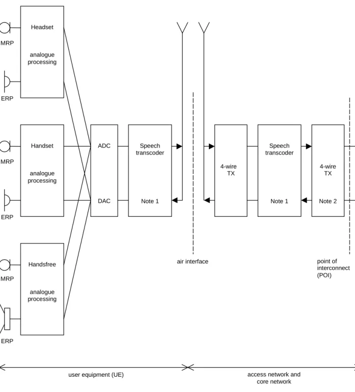
The interfaces required to define terminal acoustic characteristics are shown in figure 1. These are the air interface and the point of interconnect (POI).
The Air Interface is specified by the 3G 25 series specifications and is required to achieve user equipment (UE) transportability. Analogue measurements can be made at this point using a system simulator (SS) comprising the appropriate radio terminal equipment and speech transcoder. The losses and gains introduced by the test speech transcoder will need to be specified.
The POI with the public switched telephone network (PSTN) is considered to have a relative level of 0 dBr, where signals will be represented by 8-bit A-law, according to ITU-T Recommendation G.711 [7]. Analogue measurements may be made at this point using a standard send and receive side, as defined in ITU-T Recommendations.
Five classes of acoustic interface are considered in this specification: - Handset UE including softphone UE used as a handset; - Headset UE including softphone UE used with headset;
- Desktop-mounted hands-free UE including softphone UE with external loudspeaker(s) used in hands-free mode; - Vehicle-mounted hands-free UE including softphone UE mounted in a vehicle;
- Hand-held hands-free UE including softphone UE with internal loudspeaker(s) used in hands-free mode. (See definition of softphone in Clause 3.1)
NOTE: The requirements and performance objectives for a softphone UE shall be derived according to the following rules:
- When using a softphone UE as a handset: requirements and performance objectives shall correspond to handset mode.
- When using a softphone UE with headset: requirements and performance objectives shall correspond to headset mode.
- When a softphone UE is mounted in a vehicle: requirements and performance objectives shall correspond to vehicle-mounted handsfree mode.
- When using a softphone UE in hands-free mode:
- When using internal loudspeaker(s), requirements and performance objectives shall correspond to hand-held hands-free.
- When using external loudspeaker(s), requirements and performance objectives shall correspond to desktop-mounted hands-free.
5
Narrowband telephony transmission performance
5.1 Applicability
The performance requirements in this sub-clause shall apply when UE is used to provide narrowband telephony, either as a stand-alone service, or as part of a multimedia service.
5.2
Overall loss/loudness ratings
5.2.1 General
An international connection involving a 3G network and the PSTN should meet the overall loudness rating (OLR) limits in ITU-T Recommendation G.111 [4]. The national parts of the connection should therefore meet the send and receive loudness rating (SLR, RLR) limits in ITU-T Recommendation G.121 [5].
For the case where digital routings are used to connect the 3G network to the international chain of circuits, the SLR and RLR of the national extension will be largely determined by the SLR and RLR of the 3G network. The limits given below are consistent with the national extension limits and long term objectives in ITU-T Recommendation G.121 [5]. The SLR and RLR values for the 3G network apply up to the POI. However, the main determining factors are the
network introduces no additional loss between the Air Interface and the POI, the loudness ratings to the PSTN boundary (POI) will be the same as the loudness ratings measured at the Air Interface. However, in some cases loss adjustment may be needed for interworking situations in individual countries.
5.2.2
Connections with handset UE
The nominal values of SLR/RLR to the POI shall be: SLR = 8 ± 3 dB;
RLR = 2 ± 3 dB.
Where a user-controlled receiving volume control is provided, the RLR shall meet the nominal value for at least one setting of the control. When the control is set to maximum, the RLR shall not be ≤ (equal or louder than) -13 dB. With the volume control set to the minimum position the RLR shall not be ≥ (equal or quieter than) 18 dB. Compliance shall be checked by the relevant tests described in TS 26.132.
5.2.3
Connections with desktop and vehicle-mounted hands-free UE
The nominal values of SLR/RLR to/from the POI shall be: SLR = 13 ± 4 dB;
RLR = 2 ± 4 dB (for vehicle-mounted hands-free UE); RLR = 5 ± 4 dB (for desktop hands-free UE).
1. For a vehicle-mounted hands-free UE:
Where a user-controlled volume control is provided, the RLR shall meet the nominal value for at least one setting of the control. It is recommended that a volume control giving at least 15 dB increase from the nominal RLR (louder) is provided for hands-free units intended to work in the vehicle environment. This is to allow for the increased acoustic noise level in a moving vehicle.
RLR at the maximum volume control setting should be ≤ (equal or louder than) -2 dB. 2. For a desktop hands-free UE:
Where a user-controlled volume control is provided, the RLR shall meet the nominal value for at least one setting of the control. It is recommended that a volume control giving at least 15 dB increase from the nominal RLR (louder) is provided for hands-free units. This is to allow for the increased acoustic noise level in the usage environment.
RLR at the maximum volume control setting should be ≤ (equal or louder than) 1 dB. Compliance shall be checked by the relevant tests described in TS 26.132.
NOTE: The target value for nominal RLR, as recommended in ITU-T G.111 Annex B – Table B.1 [4], lies between 1 and 3 dB. The higher RLR requirement of 5 dB for desktop hands-free is appreciative of the limitations in transducer output with current typical form factors.
5.2.4
Connections with hand-held hands-free UE
The nominal values of SLR/RLR to/from the POI shall be: SLR = 13 ± 4 dB;
RLR = 9 +9 / -7 dB.
As a performance objective it is recommended that the RLR at the maximum volume control setting is ≤ (equal or louder than) 2 dB.
Where a user-controlled volume control is provided, the RLR shall meet the nominal value for at least one setting of the control. It is recommended that a volume control range ≥ 15 dB be provided. Compliance shall be checked by the relevant tests described in TS 26.132.
NOTE: The target value for nominal RLR, as recommended in ITU-T G.111 Annex B – Table B.1 [4], lies between 1 and 3 dB. The higher RLR requirement of 9 dB for hand-held hands-free is appreciative of the limitations in transducer output with typical form factors.
5.2.5
Connections with headset UE
The nominal values of SLR/RLR to/from the POI shall be: SLR = 8 ± 3 dB;
RLR = 2 ± 3 dB;
RLR (binaural headset) = 8 ± 3 dB for each earphone.
Where a user-controlled receiving volume control is provided, the RLR shall meet the nominal value for at least one setting of the control. When the control is set to maximum, the RLR shall not be ≤ (equal or louder than) -13 dB. With the volume control set to the minimum position the RLR shall not be ≥ (equal or quieter than) 18 dB and shall not be ≥ (equal or quieter than) 24 dB for a binaural headset.
Compliance shall be checked by the relevant tests described in 3GPP TS 26.132.
5.3
Idle channel noise (handset and headset UE)
5.3.1 Sending
The maximum noise level produced by the apparatus at the output of the SS under silent conditions in the sending direction shall be ≤ -64 dBm0p.
NOTE 1: This level includes the eventual noise contribution of an acoustic echo canceller under the condition that no signal is received.
NOTE 2: This figure applies to the total noise level with psophometric weighting. It is recommended that the level of single frequency disturbances should be ≤ -74 dBm0p in the frequency range from 300 Hz to 3.4 kHz. Compliance shall be checked by the relevant test described in TS 26.132.
5.3.2 Receiving
The maximum (acoustic) A-weighted noise level at the handset and headset UE when no signal is applied to the input of the SS shall be as follows:
If no controlled receiving volume control is provided, or, if it is provided, at the setting of the user-controlled receiving volume control at which the RLR is equal to the nominal value, the noise measured at the DRP with diffuse-field correction contributed by the receiving equipment alone shall be ≤ -57 dBPa(A). Where a volume control is provided, the measured noise shall be ≤ -54 dBPa(A) at the maximum setting of the volume control.
For the nominal volume control setting, the level of single frequency disturbances should be ≤-60 dBPa(A) in the frequency range from 100 Hz to 10 kHz. As a performance objective it is recommended that the level should be ≤ -64 dBPa(A).
NOTE: In a connection with the PSTN, noise conditions as described in ITU-T Recommendation G.103 [3] can be expected at the input (POI) of the 3G network. The characteristics of this noise may be influenced by the speech transcoding process (for further study).
5.4 Sensitivity/frequency
characteristics
5.4.1
Handset and headset UE sending
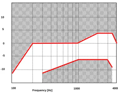
The sensitivity/frequency characteristics shall be as follows:
The sending sensitivity frequency response, measured either from the mouth reference point (MRP) to the digital interface or from the MRP to the SS audio output (digital output of the reference speech decoder of the SS), shall be within a mask, which can be drawn between the points given in table 1. The mask is drawn with straight lines between the breaking points in table 1 on a logarithmic (frequency) - linear (dB sensitivity) scale.
Table 1: Handset and headset sending sensitivity/frequency mask
Frequency (Hz) Upper limit Lower limit
100 -12 200 0 300 0 -12 1 000 0 -6 2 000 4 -6 3 000 4 -6 3 400 4 -9 4 000 0
NOTE: All sensitivity values are expressed in dB on an arbitrary scale.
100 1000 4000 0 -5 -10 10 5 Frequency [Hz]
Figure 1: Handset and headset sending sensitivity/frequency mask Compliance shall be checked by the relevant test described in TS 26.132.
5.4.2
Handset and headset UE receiving
The sensitivity/frequency characteristics shall be as follows:
The receiving sensitivity frequency response, measured either from the digital interface to the DRP with diffuse-field correction or from the SS audio input (analogue or digital input of the reference speech encoder of the SS) to the DRP with diffuse-field correction shall be within a mask, which can be drawn with straight lines between the breaking points in table 2 on a logarithmic (frequency) - linear (dB sensitivity) scale.
Table 2: Handset and headset receiving sensitivity/frequency mask for 8N application force
Frequency (Hz) Upper limit
8 ± 2 N Lower limit 8 ± 2 N 100 6 300 6 -6 3 400 6 -6 4 000 6
NOTE 1: All sensitivity values are expressed in dB on an arbitrary scale
NOTE 2: The basis for the target frequency responses in send and receive is the orthotelephonic reference response measured between 2 subjects 1 m apart under free-field conditions and assumes an ideal receive characteristic. Under these conditions the overall frequency response shows a rising slope. The present document no longer uses the ERP as the reference point for receive but the diffuse-field. With the concept of diffuse-field based receive measurements a rising slope for the overall frequency response is achieved by a flat target frequency response in send and a flat diffuse-field based receive frequency response.
0 -5 -10 10 5 100 1000 4000 Frequency [Hz]
Figure 2: Handset and headset receiving sensitivity/frequency mask for 8N application force
Compliance shall be checked by the relevant test described in TS 26.132.
5.4.3
Desktop and vehicle-mounted hands-free UE sending
The sending sensitivity frequency response from the MRP to the SS audio output (digital output of the reference speech decoder of the SS) shall be as follows:
The sending sensitivity frequency response shall be within the mask which can be drawn with straight lines between the breaking points in table 3 on a logarithmic (frequency) - linear (dB sensitivity) scale.
Table 3: Desktop and vehicle-mounted hands-free sending sensitivity/frequency mask
Frequency (Hz) Upper limit Lower limit
100 -12 200 0 300 0 -12 1 000 0 -6 2 000 4 -6 3 000 4 -6 3 400 4 -9 4 000 0
NOTE: All sensitivity values are expressed in dB on an arbitrary scale.
100 1000 4000 0 -5 -10 10 5 Frequency [Hz]
Figure 3: Desktop and vehicle-mounted hands-free sending sensitivity/frequency mask
Compliance shall be checked by the relevant test described in TS 26.132.
5.4.4
Desktop and vehicle-mounted hands-free UE receiving
The receiving sensitivity frequency response from the SS audio input (analogue or digital input of the reference speech encoder of the SS) to the free-field shall be as follows:
The receiving sensitivity frequency response shall be within the mask which can be drawn with straight lines between the breaking points in table 4 on a logarithmic (frequency) - linear (dB sensitivity) scale.
Table 4: Desktop and vehicle-mounted hands-free receiving sensitivity/frequency mask
Frequency (Hz) Upper limit Lower limit
200 6
315 6 -9
400 6 -6
3 100 6 -6
4 000 6
0 -5 -10 10 5 100 1000 4000 Frequency [Hz]
Figure 4: Desktop and vehicle-mounted receiving sensitivity/frequency mask
Compliance shall be checked by the relevant test described in TS 26.132.
5.4.5
Hand-held hands-free UE sending
The sending sensitivity frequency response from the MRP to the SS audio output (digital output of the reference speech decoder of the SS) shall be as follows:
The sending sensitivity frequency response shall be within the mask which can be drawn with straight lines between the breaking points in table 5 on a logarithmic (frequency) - linear (dB sensitivity) scale.
Table 5: Hand-held hands-free sending sensitivity/frequency mask
Frequency (Hz) Upper limit Lower limit
100 -12 200 0 300 0 -12 1 000 0 -6 2 000 4 -6 3 000 4 -6 3 400 4 -9 4 000 0
100 1000 4000 0 -5 -10 10 5 Frequency [Hz]
Figure 5: Hand-held hands-free sending sensitivity/frequency mask
Compliance shall be checked by the relevant test described in TS 26.132.
5.4.6
Hand-held hands-free UE receiving
The receiving sensitivity frequency response from the SS audio input (analogue or digital input of the reference speech encoder of the SS) to the free-field shall be as follows:
The receiving sensitivity frequency response shall be within the mask which can be drawn with straight lines between the breaking points in table 6 on a logarithmic (frequency) - linear (dB sensitivity) scale.
Table 6: Hand-held hands-free receiving sensitivity/frequency mask
Frequency (Hz) Upper limit Lower limit
200 6 500 6 -9 (Note 2) 630 6 -6 (Note 2) 800 6 -6 3 100 6 -6 4 000 6
NOTE 1: All sensitivity values are expressed in dB on an arbitrary scale.
NOTE 2: The values stated in the Table 6 for 500 and 630 Hz are listed for performance objective purposes. (not mandatory)
0 -5 -10 10 5 100 1000 4000 Frequency [Hz]
Figure 6: Hand-held hands-free receiving sensitivity/frequency mask
Compliance shall be checked by the relevant test described in TS 26.132.
5.5
Sidetone characteristics (handset and headset UE)
5.5.1 Sidetone
loss
The talker sidetone masking rating (STMR) shall be ≥ 15 dB and should be ≤ 23 dB for the nominal setting of the volume control. For all other positions of the volume control, the STMR shall be ≥ 10 dB.
Compliance shall be checked by the relevant test described in 3GPP TS 26.132. The bandwidth for the sidetone path provided by the UE may in some terminals not be restricted to the narrowband range. In case the sidetone path operates in a mode other than narrowband (to be declared by the manufacturer), compliance shall be checked using the test described for 'Wideband telephony transmission performance'.
NOTE 1: Where a user-controlled receiving volume control is provided, it is recommended that the sidetone loss is independent of the volume control setting.
NOTE 2: In general, it is recommended to provide a terminal sidetone path for handset and headset UEs. NOTE 3: In case the human air-conducted sidetone paths are obstructed (one example being some binaural insert
type headset UEs), it is important to provide a terminal sidetone path.
5.5.2 Sidetone
delay
The maximum sidetone delay should be ≤ 5 ms, measured in an echo-free setup.
NOTE: The measured result is only applicable where the level of the electrical sidetone is sufficiently high to be measured. While the STMR value may indicate the presence of sidetone it should be ensured that this is not primarily due to the acoustical or mechanical sidetone path when interpreting sidetone delay results. Compliance shall be checked by the relevant test described in TS 26.132.
digital input and digital output at the POI is ≥ 6 dB at all frequencies in the range 200 Hz to 4 kHz under the worst case acoustic conditions at the UE (any acoustic echo control should be enabled). For the normal case of digital connection between the Air Interface and the POI, the stability requirement can be applied at the Air Interface.
The worst case acoustic conditions will be as follows (with volume control set to maximum for each following condition):
Handset UE: the handset lying on, and the transducers facing, a hard surface with the ear-piece uncapped;
Headset UE: for further study;
Hands-free UE: no requirement other than echo loss.
NOTE: The test procedure must take into account the switching effects of echo control and discontinuous transmission (DTX).
5.7
Acoustic echo control
5.7.1 General
The echo loss (EL) presented by the 3G network at the POI should be sufficient during single-talk. This takes into account the fact that the UE is likely to be used in connections with high transmission delay and in a wide range of noise environments.
See ITU-T Recommendation G.131 for general guidance.
The use of acoustic echo control is not mandated for 3G networks and the connection between the UE and the POI is zero loss. Therefore the acoustic echo control provided in the UE should provide a sufficient TCLw at the POI over the likely range of acoustic end delays.
If acoustic echo control is provided by voice switching, comfort noise should be injected. This comfort noise shall operate in the same way as that used in DTX.
5.7.2
Acoustic echo control in desktop and vehicle-mounted hands-free
UE
The TCLw for the desktop and vehicle-mounted hands-free UE shall be ≥ 40 dB for any setting of the volume control. The TCLw for the desktop hands-free and vehicle-mounted hands-free UE shall be ≥ 46 dB when measured under free-field conditions at the nominal setting of the volume control.
NOTE: A TCLw for the desktop hands-free and vehicle-mounted hands-free UE of ≥ 55 dB is recommended as a performance objective when measured under free-field conditions at the nominal setting of the volume control. Depending on the UE idle channel noise in the sending direction, it may not always be possible to measure an echo loss ≥ 55 dB.
The echo canceller should be designed to cope with the expected reverberation and dispersion. In the case of the hands-free UE, this reverberation and dispersion may be time variant. Compliance with this requirement shall be checked by the relevant test described in TS 26.132.
5.7.3
Acoustic echo control in hand-held hands-free UE
The TCLw for hand-held hands-free UE shall be ≥ 40 dB for any setting of the volume control. The TCLw for hand-held hands-free UE shall be ≥ 46 dB at the nominal setting of the volume control.
NOTE: A TCLw for the hand-held hands-free UE of ≥ 55 dB is recommended as a performance objective when measured under free-field conditions at the nominal setting of the volume control. Depending on the UE idle channel noise in the sending direction, it may not always be possible to measure an echo loss ≥ 55 dB.
The echo canceller should be designed to cope with the expected reverberation and dispersion. In the case of the hands-free UE, this reverberation and dispersion may be time variant. Compliance with this requirement shall be checked by the relevant test described in TS 26.132.
5.7.4
Acoustic echo control in a handset UE
The TCLw for handset UE shall be ≥ 46 dB for any setting of the volume control.
The TCLw for handset UE should be ≥ 55 dB at the nominal setting of the volume control.
NOTE: It is recommended that the volume control should be set back to nominal after each call unless TCLw ≥ 55 dB can also be maintained with the maximum volume setting. Depending on the UE idle channel noise in the sending direction, it may not always be possible to measure an echo loss ≥ 55 dB.
The echo canceller should be capable of dealing with the variations in handset positions when in normal use. The implications of this are under study. Compliance with this requirement shall be checked by the relevant test described in TS 26.132.
5.7.5
Acoustic echo control in a headset UE
The TCLw for headset UE shall be ≥ 46 dB for any setting of the volume control.
The TCLw for headset UE should be ≥ 55 dB at the nominal setting of the volume control.
NOTE: It is recommended that the volume control should be set back to nominal after each call unless TCLw ≥ 55 dB can also be maintained with the maximum volume setting. Depending on the UE idle channel noise in the sending direction, it may not always be possible to measure an echo loss ≥ 55 dB.
The echo canceller should be designed to cope with the expected reverberation and dispersion. Compliance with this requirement shall be checked by the relevant test described in TS 26.132.
5.8 Distortion
5.8.1 Sending
distortion
The sending part shall meet the following distortion requirements:
NOTE 1: Digital signal processing other than the transcoder itself is included in this requirement (e.g. echo cancelling). Distortion shall be measured between the MRP and the SS audio output (output of the reference speech decoder of the SS). The ratio of signal-to-total distortion power measured with the proper noise weighting (see table 4 of ITU-T Recommendation G.223) shall be above the limits given in table 7.
Table 7: Limits for signal-to-total distortion ratio
Sending level (dBPa at the MRP) Sending Ratio (dB) 5 30 0 35 -4,7 35 -10 33 -15 30 -20 27
Limits for intermediate levels are found by drawing straight lines between the breaking points in table 7 on a linear (dB signal level) - linear (dB ratio) scale.
NOTE 2: It should be ensured that the test signal is treated by speech processing algorithms as a speech-like signal, and not a noise-like signal. Test signals with a time-stationary envelope may be treated by certain algorithms, e.g., noise suppression algorithms defined in 3GPP TS 06.77 R99 [16], as a noise-like signal. If speech processing algorithms, including but not limited to noise suppression algorithms, are shown to treat the test signal as a noise-like signal, even where an activation signal has been utilized,then the test should be repeated with said speech processing algorithms disabled. The results of both sets of tests and the state of the processing algorithms should be documented in the test report.
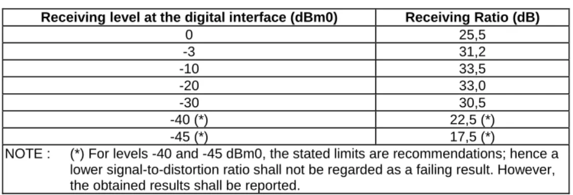
5.8.2 Receiving
The receiving part between the SS audio input (input of the reference speech encoder of the SS) and the DRP with diffuse-field correction shall meet the requirements in this sub-clause at the nominal setting of the volume control: The ratio of signal-to-total distortion power measured with the proper noise weighting (see table 4 of ITU-T Recommendation G.223) shall be above the limits given in table 8 when the sound pressure at the DRP with diffuse-field correction is up to 10 dBPa. For a sound pressure ≥ 10 dBPa at the DRP with diffuse-field correction there is no distortion requirement.
Table 8: Limits for signal-to-total distortion ratio
Receiving level at the digital interface (dBm0) Receiving Ratio (dB)
0 25,5 -3 31,2 -10 33,5 -20 33,0 -30 30,5 -40 (*) 22,5 (*) -45 (*) 17,5 (*)
NOTE : (*) For levels -40 and -45 dBm0, the stated limits are recommendations; hence a lower signal-to-distortion ratio shall not be regarded as a failing result. However, the obtained results shall be reported.
Limits for intermediate levels are found by drawing straight lines between the breaking points in the table on a linear (dB signal level) - linear (dB ratio) scale.
Compliance of the receiving distortion shall be checked by the appropriate test method in TS 26.132.
NOTE 1: It should be ensured that the test signal is treated by speech processing algorithms as a speech-like signal, and not a noise-like signal. Test signals with a time-stationary envelope may be treated by certain algorithms, e.g. noise suppression algorithms defined in 3GPP TS 06.77 R99 [16], as a noise-like signal. If speech processing algorithms, including but not limited to noise suppression algorithms, are shown to treat the test signal as a noise-like signal, even where an activation signal has been utilized,then the test should be repeated with said speech processing algorithms disabled. The results of both sets of tests and the state of the processing algorithms should be documented in the test report.
5.9
Ambient noise rejection
Handset and Headset UE:
The nature of mobile telephony is such that the UE will typically be operated in high ambient acoustic noise. Due to the adverse interaction of noise signals with speech codecs operating at lower bit-rates, e.g., ≥ 8 kbit/s, a minimum noise rejection specification is required.
The UE ambient noise rejection, ANR, calculated as a Single Figure DELSM (SFDELSM) should be ≥ the nominal value of 0 dB. Due to the uncertainty inherent in the measurement method for ANR, a ± 3 dB tolerance is allowed on the nominal value.
For good performance, it is recommended that a figure of 3 dB should be achieved. Compliance shall be checked by the relevant test described in 3GPP TS 26.132.
NOTE: The ambient noise rejection method has been updated to support basic testing of UEs that include noise suppression. The above requirement has been adapted to a recommendation, in the interim, for this reason. New requirements are under study.
Hands-free UE (all categories):
No requirement in hands-free operations.
MRP ERP MRP ERP MRP ERP ADC DAC Speech transcoder Note 1 Handset analogue processing Headset analogue processing Handsfree analogue processing Speech transcoder Note 1 4-wire TX 4-wire TX Note 2 point of interconnect (POI) air interface
user equipment (UE) access network and core network
NOTE 1: Includes DTX functionality.
NOTE 2: Connection to PSTN should include electrical echo control (EEC).
5.10
Information on other parameters (not normative)
Information about additional parameters relevant to speech quality, e.g., for terminals where signal processing is used, can be found in ITU-T Recommendations P.340, P.501 and P.502.
5.11
Sending performance in the presence of ambient noise
5.11.1 General
For sending, in handset mode, the UE shall reduce the ambient noise picked up by the microphone(s) without significantly degrading the quality of the speech signal.
5.11.2
Connections with handset UE
The UE shall comply with the following requirements: S-MOS-LQOn
• The average of S-MOS-LQOn scores across all test conditions shall be ≥ 3.0
• As a performance objective, the average of the S-MOS-LQOn scores across all test conditions should be ≥ 3.5 N-MOS-LQOn
• The average of the N-MOS-LQOn scores across all test conditions shall be ≥ 2.3
• As a performance objective, the average of N-MOS-LQOn scores across all test conditions should be ≥ 3.0 G-MOS-LQOn
• No requirement.
Compliance shall be checked by the relevant tests described in 3GPP TS 26.132.
5.12 Delay
5.12.1 Handset
UE
It is in general desirable to minimize UE delays to ensure low enough end-to-end delays and hence a good conversational experience, guidance is found in ITU-T Recommendation G.114.
For UMTS circuit-switched and AMR speech codec operation, the sum of the UE delays in sending and receiving directions (TS + TR) shall in any case be ≤ 220ms and should be ≤ 185ms.
NOTE: A delay ≤ 185 ms might not be achievable in some cases due to UE implementation trade-offs between delay and other parameters such as speech quality enhancement, performance of noise reduction or UE power consumption optimization, and UE implementation issues such as rebuffering between
components.
Compliance shall be checked by the relevant test described in 3GPP TS 26.132.
5.12.2 Headset
UE
5.12.2.1 Wired
headset
It is in general desirable to minimize UE delays to ensure low enough end-to-end delays and hence a good conversational experience, guidance is found in ITU-T Recommendation G.114.
For UMTS circuit-switched and AMR speech codec operation, the sum of the UE delays in sending and receiving directions (TS + TR) shall in any case be ≤ 220ms and should be ≤ 185ms.
NOTE: A delay ≤ 185 ms might not be achievable in some cases due to UE implementation trade-offs between delay and other parameters such as speech quality enhancement, performance of noise reduction or UE power consumption optimization, and UE implementation issues such as rebuffering between
components.
Compliance shall be checked by the relevant test described in 3GPP TS 26.132.
5.12.2.2 Wireless
headset
For further study.
5.13
Echo control characteristics
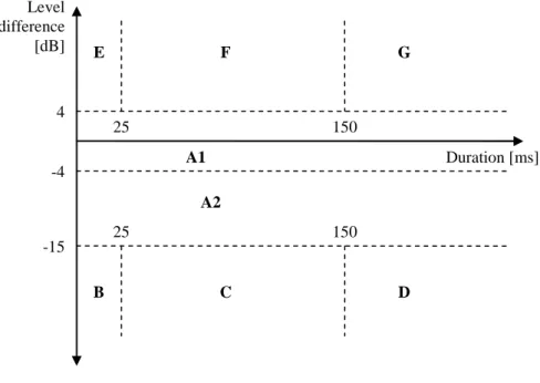
Echo cancellation is commonly deployed in the UE to fulfil the Acoustic echo control requirements. Echo cancellers are complex devices of which the subjective performance is affected by several attributes. The main attribute is its ability to suppress echo. The process of suppressing the echo may introduce impairments to the near-end speech signal, mainly manifested as distortion or clipping of the near-end signal during simultaneous speech from both the far and near-end ('double-talk').
To characterise the echo control performance, the activity (in % of total time) and averaged level difference (in dB) of the duration of any level difference according to Figure 6a and Table 8a between the clean near-end signal and the send-signal shall be reported for 'double-talk' as well as the far-end single talk periods adjacent to the 'double-talk'.
NOTE: The limits for specifying the categories in Figure 6a and Table 8a are provisional pending further analysis and validation.
NOTE: The categories in Figure 6a and Table 8a are labelled in a functional order and the subjective impression of the respective categories is for further study.
All percentage values and averaged level differences described in the relevant test of 3GPP TS 26.132 shall be reported.
Level difference [dB] Duration [ms] 4 -4 -15 25 25 150 150 A1 A2 C B D E F G
Table 8a: Categories for echo canceller performance classification
Category Description
A1 Full-duplex and full transparency
A2 Full-duplex with level loss in Tx
B Very short clipping
C Short clipping resulting in loss of syllables
D Clipping resulting in loss of words
E Very short residual echo
F Echo bursts
G Continuous echo
5.13.1 Handset
Requirements are for further study.
5.13.2 Headset
Requirements are for further study.
5.13.3 Handheld
hands-free
Requirements are for further study.
5.13.4
Desktop and vehicle mounted hands-free
Requirements are for further study.
6
Wideband telephony transmission performance
6.1 Applicability
The performance requirements in this clause shall apply when UE is used to provide wideband telephony, either as a stand-alone service, or as part of a multimedia service. The requirements in the clause apply only when the far-end terminal is also providing wideband, and not narrowband telephony. When a wideband-enabled terminal is providing narrowband telephony, the requirements in clause 5, "narrowband telephony transmission performance" shall apply.
6.2
Overall loss/loudness ratings
6.2.1 General
An international connection involving a 3G network and the PSTN should meet the overall loudness rating (OLR) limits in ITU-T Recommendation G.111 [4]. The national parts of the connection should therefore meet the send and receive loudness rating (SLR, RLR) limits in ITU-T Recommendation G.121 [5].
For the case where digital routings are used to connect the 3G network to the international chain of circuits, the SLR and RLR of the national extension will be largely determined by the SLR and RLR of the 3G network. The limits given below are consistent with the national extension limits and long term objectives in ITU-T Recommendation G.121 [5]. The SLR and RLR values for the 3G network apply up to the POI. However, the main determining factors are the characteristics of the UE, including the analogue to digital conversion (ADC) and digital to analogue conversion (DAC). In practice, it is convenient to specify loudness ratings to the Air Interface. For the normal case, where the 3G network introduces no additional loss between the Air Interface and the POI, the loudness ratings to the PSTN boundary (POI) will be the same as the loudness ratings measured at the Air Interface. However, in some cases loss adjustment may be needed for interworking situations in individual countries.
6.2.2
Connections with handset UE
The nominal values of SLR/RLR to the POI shall be: SLR = 8 ± 3 dB;
RLR = 2 ± 3 dB.
Where a user-controlled receiving volume control is provided, the RLR shall meet the nominal value for at least one setting of the control. When the control is set to maximum, the RLR shall not be ≤ (equal or louder than) -13 dB and shall not be ≥ (equal or quieter than) -3 dB.
With the volume control set to the minimum position the RLR shall not be ≥ (equal or quieter than) 18 dB. Compliance shall be checked by the relevant tests described in TS 26.132.
6.2.3
Connections with desktop and vehicle-mounted hands-free UE
The nominal values of SLR/RLR to/from the POI shall be: SLR = 13 ± 4 dB;
RLR = 2 ± 4 dB (for vehicle-mounted hands-free UE); RLR = 5 ± 4 dB (for desktop hands-free UE).
1. For a vehicle-mounted hands-free UE:
Where a user-controlled volume control is provided, the RLR shall meet the nominal value for at least one setting of the control. It is recommended that a volume control giving at least 15 dB increase from the nominal RLR (louder) is provided for hands-free units intended to work in the vehicle environment. This is to allow for the increased acoustic noise level in a moving vehicle.
RLR at the maximum volume control setting should be ≤ (equal or louder than) -2 dB. 2. For a desktop hands-free UE:
Where a user-controlled volume control is provided, the RLR shall meet the nominal value for at least one setting of the control. It is recommended that a volume control giving at least 15 dB increase from the nominal RLR (louder) is provided for hands-free units. This is to allow for increased acoustic noise level in the usage environment.
RLR at the maximum volume control setting should ≤ (equal or louder than) 1 dB. Compliance shall be checked by the relevant tests described in TS 26.132.
NOTE: The target value for nominal RLR, as recommended in ITU-T G.111 Annex B – Table B.1 [4], lies between 1 and 3 dB. The higher RLR requirement of 5 dB for desktop hands-free is appreciative of the limitations in transducer output with current typical form factors.
6.2.4
Connections with hand-held hands-free UE
The nominal values of SLR/RLR to/from the POI shall be: SLR = 13 ± 4 dB;
RLR = 9 +9/-7 dB.
Where a user-controlled volume control is provided, the RLR shall meet the nominal value for at least one setting of the control.
The value of RLR at the maximum volume control shall be ≤ (equal or louder than) 12 dB. As a performance objective it is recommended that the RLR at the maximum volume control setting is ≤ (equal or louder than) 2 dB.
Where a user-controlled volume control is provided, the RLR shall meet the nominal value for at least one setting of the
6.2.5
Connections with headset UE
The SLR and RLR should be measured and computed using methods given in ITU-T Recommendation P.380 [9]. This Recommendation currently gives a measuring technique for supra-aural earphone and insert type receivers. Study is continuing on other types of ear-pieces in ITU-T Study Group 12.
The nominal values of SLR/RLR to/from the POI shall be: SLR = 8 ± 3 dB;
RLR = 2 ± 3 dB;
RLR (binaural headset) = 8 ± 3 dB for each earphone.
Where a user-controlled receiving volume control is provided, the RLR shall meet the nominal value for at least one setting of the control. When the control is set to maximum, the RLR shall not be ≤ (equal or louder than) -13 dB. With the volume control set to the minimum position the RLR shall not be ≥ (equal or quieter than) 18 dB and shall not be ≥ (equal or quieter than) 24 dB for a binaural headset.
Compliance shall be checked by the relevant tests described in 3GPP TS 26.132.
6.3
Idle channel noise (handset and headset UE)
6.3.1 Sending
The maximum noise level produced by the apparatus at the output of the SS under silent conditions in the sending direction shall not exceed -64 dBm0(A).
NOTE 1: This level includes the eventual noise contribution of an acoustic echo canceller under the condition that no signal is received.
NOTE 2: This figure applies to the total noise level with A-weighting. It is recommended that the level of single frequency disturbances should be ≤-74 dBm0(A) in the frequency range from 100 Hz to 8 kHz. Compliance shall be checked by the relevant test described in TS 26.132.
6.3.2 Receiving
The maximum (acoustic) noise level at the handset and headset UE when no signal is transmitted to the input of the SS shall be as follows:
If no controlled receiving volume control is provided, or, if it is provided, at the setting of the user-controlled receiving volume control at which the RLR is equal to the nominal value, the noise measured at the DRP with diffuse-field correction contributed by the receiving equipment alone shall not exceed -57 dBPa(A). Where a volume control is provided, the measured noise shall be ≤ -54 dBPa(A) at the maximum setting of the volume control.
For the nominal volume control setting, the level of single frequency disturbances shall be ≤-60 dBPa(A) in the frequency range from 100 Hz to 10 kHz. As a performance objective it is recommended that the level should be ≤ -64 dBPa(A).
NOTE: In a connection with the PSTN, noise conditions as described in ITU-T Recommendation G.103 [3] can be expected at the input (POI) of the 3G network. The characteristics of this noise may be influenced by the speech transcoding process (for further study).
Compliance shall be checked by the relevant test described in TS 26.132.
6.4 Sensitivity/frequency
characteristics
6.4.1
Handset and headset UE sending
The sensitivity/frequency characteristics shall be as follows:
The sending sensitivity frequency response, measured either from the mouth reference point (MRP) to the digital interface or from the MRP to the SS audio output (digital output of the reference speech decoder of the SS), shall be within a mask, which can be drawn between the points given in table 9. The mask is drawn with straight lines between the breaking points in table 1 on a logarithmic (frequency) - linear (dB sensitivity) scale.
Table 9: Handset and headset sending sensitivity/frequency mask
Send sensitivity/frequency response Frequency (Hz)
Upper limit Lower limit
100 0
200 5 -5
5 000 5 -5
6 300 5 -10
8 000 5
NOTE: All sensitivity values are expressed in dB on an arbitrary scale.
100 1000 0 -5 -10 10 5 10000 Frequency [Hz]
Figure 9: Handset and headset sending sensitivity/frequency mask
Compliance shall be checked by the relevant test described in TS 26.132.
6.4.2
Handset and headset UE receiving
The sensitivity/frequency characteristics shall be as follows:
The receiving sensitivity frequency response, measured either from the digital interface to the DRP with diffuse-field correction or from the SS audio input (analogue or digital input of the reference speech encoder of the SS) to the DRP with diffuse-field correction, shall be within a mask, which can be drawn with straight lines between the breaking points in table 10 on a logarithmic (frequency) - linear (dB sensitivity) scale.
Table 10: Handset and headset receiving sensitivity/frequency mask
Frequency (Hz) Upper limit
8 ± 2 N Lower limit 8 ± 2 N 100 6 200 6 -10 300 6 -6 1 000 6 -6 2 000 8 -6 5 000 8 -6 6 300 8 -12 8 000 8
NOTE: All sensitivity values are expressed in dB on an arbitrary scale.
NOTE: The limits in the table above are enforced but are under evaluation. The values are expected to be modified taking into account that the change from ERP to diffuse-field correction is reflected in the table. Compliance shall be checked by the relevant test described in TS 26.132.
6.4.3
Desktop and vehicle-mounted hands-free UE sending
The sending sensitivity frequency response from the MRP to the SS audio output (digital output of the reference speech decoder of the SS) shall be as follows:
The sending sensitivity frequency response shall be within the mask which can be drawn with straight lines between the breaking points in table 11 on a logarithmic (frequency) - linear (dB sensitivity) scale.
Table 11: Desktop and vehicle-mounted hands-free sending sensitivity/frequency mask
Frequency (Hz) Upper limit Lower limit
100 0 200 5 -5 5 000 5 -5
6 300 5 -10 8 000 5
NOTE: All sensitivity values are expressed in dB on an arbitrary scale. 100 1000 0 -5 -10 10 5 10000 Frequency [Hz]
Compliance shall be checked by the relevant test described in TS 26.132.
6.4.4
Desktop and vehicle-mounted hands-free UE receiving
The receiving sensitivity frequency response from the SS audio input (analogue or digital input of the reference speech encoder of the SS) to the free-field shall be as follows:
The receiving sensitivity frequency response shall be within the mask which can be drawn with straight lines between the breaking points in table 12 on a logarithmic (frequency) - linear (dB sensitivity) scale.
Table 12: Desktop and vehicle-mounted hands-free receiving sensitivity/frequency mask
Frequency Upper limit Lower limit
125 Hz 8 200 Hz 8 -12 250 Hz 8 -9 315 Hz 7 -6 400 Hz 6 -6 5 000 Hz 6 -6 6 300 Hz 6 -9 8 000 Hz 6 -∞
NOTE: The limits for intermediate frequencies lie on a straight line drawn between the given values on a linear (dB) - logarithmic (Hz) scale.
All sensitivity values are expressed in dB on an arbitrary scale. 100 1000 0 -5 -10 10 5 10000 Frequency [Hz]
Figure 12: Desktop and vehicle-mounted hands-free receiving sensitivity/frequency mask
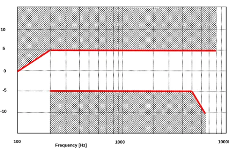
It is recommended as a performance objective that the receiving sensitivity frequency response be within the mask which can be drawn with straight lines between the breaking points in table 12.a on a logarithmic (frequency) - linear (dB sensitivity) scale.
Table 12a: Performance objective for desktop and vehicle-mounted hands-free receiving sensitivity/frequency response
Frequency (Hz) Upper limit Lower limit
100 0 200 0 -18 250 0 -15 315 0 -12 6 300 0 -12 8 000 0 100 1000 -15 5 0 -5 -10 10000 Frequency [Hz]
Figure 12a: Performance objective for desktop and vehicle-mounted hands-free receiving sensitivity/frequency response
Compliance shall be checked by the relevant test described in TS 26.132.
6.4.5
Hand-held hands-free UE sending
The sending sensitivity frequency response from the MRP to the SS audio output (digital output of the reference speech decoder of the SS) shall be as follows:
The sending sensitivity frequency response shall be within the mask which can be drawn with straight lines between the breaking points in table 13 on a logarithmic (frequency) - linear (dB sensitivity) scale.
Table 13: Hand-held hands-free sending sensitivity/frequency mask
Frequency (Hz) Upper limit Lower limit
100 0 200 5 -5 5 000 5 -5
6 300 5 -10 8 000 5
NOTE: All sensitivity values are expressed in dB on an arbitrary scale.
100 1000 0 -5 -10 10 5 10000 Frequency [Hz]
Figure 13: Hand-held hands-free sending sensitivity/frequency mask
Compliance shall be checked by the relevant test described in TS 26.132.
6.4.6
Hand-held hands-free UE receiving
The receiving sensitivity frequency response from the SS audio input (analogue or digital input of the reference speech encoder of the SS) to the free-field shall be as follows:
The receiving sensitivity frequency response shall be within the mask which can be drawn with straight lines between the breaking points in table 14 on a logarithmic (frequency) - linear (dB sensitivity) scale.
Table 14: Hand-held hands-free receiving sensitivity/frequency mask
Frequency (Hz) Upper limit Lower limit
315 6 630 6 -12 800 6 -6 4 000 6 -6 6 300 6 -12 8 000 6
100 1000 0 -5 -10 10 5 10000 Frequency [Hz]
Figure 14: Hand-held hands-free receiving sensitivity/frequency mask
It is recommended as a performance requirement that the receiving sensitivity frequency response be within the mask which can be drawn with straight lines between the breaking points in table 14a on a logarithmic (frequency) - linear (dB sensitivity) scale.
Table 14a: Performance objective for hand-held hands-free receiving sensitivity/frequency mask
Frequency (Hz) Upper limit Lower limit
315 6 400 6 -12 500 6 -6 4 000 6 -6 6 300 6 -12 8 000 6
NOTE: All sensitivity values are expressed in dB on an arbitrary scale. 100 1000 0 -5 -10 10 5 10000 Frequency [Hz]
Compliance shall be checked by the relevant test described in TS 26.132.
6.5
Sidetone characteristics (handset and headset UE)
6.5.1 Sidetone
loss
The talker sidetone masking rating (STMR) shall be ≥ 15 dB and should be ≤ 23 dB for the nominal setting of the volume control. For all other positions of the volume control, the STMR shall be ≥ 10 dB.
Compliance shall be checked by the relevant test described in TS 26.132.
NOTE 1: Where a user-controlled receiving volume control is provided, it is recommended that the sidetone loss is independent of the volume control setting.
NOTE 2: In general, it is recommended to provide a terminal sidetone path for handset and headset UEs. NOTE 3: In case the human air-conducted sidetone paths are obstructed (one example being some binaural insert
type headset UEs), it is important to provide a terminal sidetone path.
6.5.2 Sidetone
delay
The maximum sidetone delay shall be ≤ 5 ms, measured in an echo-free setup.
NOTE: The measured result is only applicable where the level of the electrical sidetone is sufficiently high to be measured. While the STMR value may indicate the presence of sidetone it should be ensured that this is not primarily due to the acoustical or mechanical sidetone path when interpreting sidetone delay results. Compliance shall be checked by the relevant test described in TS 26.132.
6.6 Stability
loss
The stability loss presented to the PSTN by the 3G network at the POI should meet the principles of the requirements in clauses 2 and 3 of ITU-T Recommendation G.122 [6]. These requirements will be met if the attenuation between the digital input and digital output at the POI is ≥ 6 dB at all frequencies in the range 100 Hz to 8 kHz under the worst case acoustic conditions at the UE (any acoustic echo control should be enabled). For the normal case of digital connection between the Air Interface and the POI, the stability requirement can be applied at the Air Interface.
The worst case acoustic conditions will be as follows (with volume control set to maximum for each following condition):
Handset UE: the handset lying on, and the transducers facing, a hard surface with the ear-piece uncapped;
Headset UE: for further study;
Hands-free UE: no requirement other than echo loss.
NOTE: The test procedure must take into account the switching effects of echo control and discontinuous transmission (DTX).
6.7
Acoustic echo control
6.7.1 General
The echo loss (EL) presented by the 3G network at the POI should be sufficient during single-talk. This takes into account the fact that the UE is likely to be used in connections with high transmission delay and in a wide range of noise environments.
The use of acoustic echo control is not mandated for 3G networks and the connection between the UE and the POI is zero loss. Therefore the acoustic echo control provided in the UE should provide a sufficient TCLw at the POI over the likely range of acoustic end delays.
If acoustic echo control is provided by voice switching, comfort noise should be injected. This comfort noise shall operate in the same way as that used in DTX.
6.7.2
Acoustic echo control in desktop and vehicle-mounted hands-free
UE
The TCLw for the desktop and vehicle-mounted hands-free UE shall be ≥ 40 dB for any setting of the volume control. The TCLw for the desktop hands-free and vehicle-mounted hands-free UE shall be ≥ 46 dB when measured under free-field conditions at the nominal setting of the volume control.
NOTE: A TCLw for desktop hands-free and vehicle-mounted hands-free UE of ≥ 55 dB is recommended as a performance objective when measured under free-field conditions at the nominal setting of the volume control. Depending on the UE idle channel noise in the sending direction, it may not always be possible to measure an echo loss ≥ 55 dB.
The echo canceller should be designed to cope with the expected reverberation and dispersion. In the case of the hands-free UE, this reverberation and dispersion may be time variant. Compliance with this requirement shall be checked by the relevant test described in TS 26.132.
6.7.3
Acoustic echo control in hand-held hands-free UE
The TCLw for hand-held hands-free UE shall be ≥ 40 dB for any setting of the volume control. The TCLw for hand-held hands-free UE shall be ≥ 46 dB at the nominal setting of the volume control.
NOTE: A TCLw for the hand-held hands-free UE of ≥ 55 dB is recommended as a performance objective when measured under free-field conditions at the nominal setting of the volume control. Depending on the UE idle channel noise in the sending direction, it may not always be possible to measure an echo loss ≥ 55 dB.
The echo canceller should be designed to cope with the expected reverberation and dispersion. In the case of the hands-free UE, this reverberation and dispersion may be time variant. Compliance with this requirement shall be checked by the relevant test described in TS 26.132.
6.7.4
Acoustic echo control in a handset UE
The TCLw for handset UE shall be ≥ 46 dB for any setting of the volume control.
The TCLw for handset UE should be ≥ 55 dB at the nominal setting of the volume control. With the volume control set to maximum TCLw should be ≥55 dB.
It is recommended that the volume control should be set back to nominal after each call unless TCLw ≥ 55 dB can also be maintained with the maximum volume setting.
NOTE. Depending on the UE idle channel noise in the sending direction, it may not always be possible to measure an echo loss ≥ 55 dB.
The echo canceller should be capable of dealing with the variations in handset positions when in normal use. The implications of this are under study.
Compliance with this requirement shall be checked by the relevant test described in TS 26.132.
6.7.5
Acoustic echo control in a headset UE
The TCLw for headset UE shall be ≥ 55 dB at the nominal setting of the volume control.
The volume control shall be set back to nominal after each call unless a TCLw ≥ 55 dB can also be maintained with the maximum volume setting.
NOTE: Depending on the UE idle channel noise in the sending direction, it may not always be possible to measure an echo loss ≥ 55 dB.
Due to the obstacle effect of the head in this type of terminal, careful design might mean that no active echo control is necessary.
The echo cancellation algorithm should be designed to cope with the expected reverberation and dispersion. Compliance with this requirement shall be checked by the relevant test described in TS 26.132.
6.8 Distortion
6.8.1 Sending
distortion
The sending part shall meet the following distortion requirements:
NOTE 1: Digital signal processing other than the transcoder itself is included in this requirement (e.g., echo cancelling).
Distortion shall be measured between the MRP and the SS audio output (output of the reference speech decoder of the SS). The ratio of signal-to-total distortion power measured with the proper noise weighting (see table 4 of ITU-T Recommendation G.223) shall be above the limits given in table 15.
NOTE 2: Frequencies from 315 Hz to 816 Hz do not apply to the hands-free UE case, but only to handset and headset UE.
Table 15: Limits for signal-to-total distortion ratio
Frequency (Hz) Sending level
(dBPa at the MRP) Sending Ratio (dB) 315 -4,7 28 408 -4,7 32 510 -4,7 32 816 -4,7 32 1 020 5 30 0 35 -4.7 35 -10 33 -15 30 -20 27
Limits for intermediate levels are found by drawing straight lines between the breaking points in table 15 on a linear (dB signal level) - linear (dB ratio) scale.
Compliance of the sending distortion shall be checked by the test described in TS 26.132.
NOTE 3: It should be ensured that the test signal is treated by speech processing algorithms as a speech-like signal, and not a noise-like signal. Test signals with a time-stationary envelope may be treated by certain algorithms, e.g., noise suppression algorithms defined in 3GPP TS 06.77 R99 [16], as a noise-like signal. If speech processing algorithms, including but not limited to noise suppression algorithms, are shown to treat the test signal as a noise-like signal, even where an activation signal has been utilized,then the test should be repeated with said speech processing algorithms disabled. The results of both sets of tests and the state of the processing algorithms should be documented in the test report.