Vectorworks 2015 Tutorial
* * * *
D r a f t i n g t h e F r o n t E l e v a t i o n
* * * *
w i t h I n t r o d u c t i o n t o M o d e l i n g , Te x t u r i n g , L i g h t i n g a n d R e n d e r i n g
written by Kent Goetzrevised 12/19/2014
This tutorial contains a set of instructions designed to lead the user through a series of activities that one may encounter when designing a scenic space. An example of the completed tutorial project is provided on the last page. The tutorial project does not represent a design for any specific play. The project is simply a composition of basic units composed in a theatrical situation designed to introduce the user to the basic tools and commands of VectorWorks.
The tutorial assumes that the user has a basic knowledge of either Macintosh or Windows operating systems and a general understanding of stage terminology, i.e. stage left is actually the audiences right, upstage is farther away from the audience, etc. If the tutorial is successful, then upon completion the user should feel both motivated and sufficiently skilled to continue exploring more complex and creative ways to employ this application.
On page 2 is a diagram of the VectorWorks interface, followed by an illustration showing VectorWorks keyboard shortcuts. Please familiarize yourself with these pages before you begin the tutorial instructions which follow. It is advisable to execute each step of the tutorial sequentially and to read through each activity completely before executing. Referring often to the example of the completed project can also be helpful. Please note that as you progress through the tutorial the instructions become less specific assuming that you have been acquiring skills as you execute the various tutorial activities. For increased retention of skills, it is suggested that after executing 5-10 actions by reading the tutorial instructions, you Undo those actions and execute them again without reading the instructions.
This tutorial was written using the Macintosh operating system. Some illustrations may have a different appearance for those using Windows, and some menu commands and keyboard shortcuts may be different, i.e., on the Mac the z, or Commandkey, is the Control key in Windows, Option = Alt , Delete = Backspace, Return = Enter, et al.
! Note: -- To execute modeling and rendering portion of this tutorial you will need the Spotlight version of VectorWorks with RenderWorks; and the files: “VWTutorialItems.vwx”; “Wallpaper.jpg”; “Clouds.jpg” and “Figure1.jpg.” All files are available through the tutorial website.
INDEX
page
2 DIAGRAM OF VECTORWORKS INTERFACE
3 1) PREPARE DRAWING ENVIRONMENT FOR NEW PROJECT
6 2) DRAW PLAN VIEW OF WALLS
9 3) DRAW PLAN VIEW OF WINDOW IN LEFT WALL
10 4) DRAW PLAN VIEW OF DOOR IN RIGHT WALL
12 5) DRAW FRONT ELEVATIONS OF WALLS
13 6) ADD WINDOW OPENING AND SASHES TO THE 5’ WALL
15 7) ADD TRIM TO THE WINDOW
17 8) ADD CURTAINS
17 9) ADD DOOR
19 10) ADD ESCUTCHEON AND DOOR KNOB
19 11)ADD DOOR TRIM AND PANEL DETAIL
20 12) ADD WALL MOLDING
22 13) CREATE SECTION VIEW OF WALL
27 14) DIMENSION, NOTATE AND ADD MOLDING DETAILS
30 15) ADD LABELS, NOTES AND TITLE BLOCK
32 16) BUILD 3D MODEL OF WALLS
33 17) ADD 3D WINDOW, DOOR AND PLATFORM
37 18) ESTABLISH PERSPECTIVE VIEW AND ADD 3D BACKDROP 38 19) ADD 3D MOLDING, FIGURE AND CHAIR
42 20) ADD TEXTURE TO SURFACES
48 21) LIGHT THE SPACE
54 22) ADD A COSTUMED FIGURE
55 23) PREPARE RENDERING FOR PRINT
57 SAMPLE OF FRONT ELEVATION OF WALLS
58 SAMPLE OF RENDERING
59 SAMPLE OF SKETCH
Applications used to create tutorial:VectorWorks 2015 by Nemetschek, North America and Pages ’09 by Apple. For permission to copy and distribute this document contact: Kent Goetz - [email protected]
VectorWorks Standard Keyboard Shortcuts
Print the template above on heavy paper and affix it to a convenient surface in your work area.
There are many other standard keyboard shortcuts using the Shift and Option-Shift modifiers. The above shortcuts were posted by David LaBarbera AIA on the Vectorworks TechBoard 2008: http://techboard.nemetschek.net/ubbthreads/ubbthreads.php?ubb=showflat&Number=98927 .
1) PREPARE DRAWING ENVIRONMENT FOR NEW PROJECT
♢ Open the VectorWorks 2015 application. A new blank file should appear on screen. If not, under File select New (File > New) .
Select Create blank document and click OK.
♢ In the Menu Bar, under Tools > Workspaces > Spotlight. This controls the organization and visibility of menu commands and
palettes. Workspace options vary depending on the VectorWorks package you have. i.e., Standard, Spotlight, Architect, etc..
♢ Under VectorWorks > Preferences (z , in MacOS [Control , in Windows]). Check to see that the formatting matches each of the
six windows illustrated in {Figures 1a-f} on next page and click OK. (Almost all of the default settings are fine for this tutorial, except the “Offset duplications”, which I recommend deselecting and the Auto Save, which I prefer to do myself. However, it will be helpful for you to have an overview of the preference options available.) These preferences will remain every time you use
VectorWorks on this computer until you change them, which can be done anytime to best suit your individual drawing style and the specific needs of a project.
Fig 1a Fig 1b Fig 1c
Fig 1d
Turn Autosave off if you find it a nuisance.
Fig 1e
♢ To unclutter your desktop for now, under Window > Palettes deselect the Working Planes, Resources Browser and Visualization
palettes, or click the hide button at the top of the palette. {Fig. 2a}
♢ In the Snapping Palette, turn on just Snap to Object, Constrain Angle and Smart Points. {Fig. 2b}
Snap to Object Constrain Angle Smart Points Snap to Grid Smart Edge Snap to Intersection Snap to Distance Constrain Tangent Fig 2a Fig 2b
♢ Under File > Page Setup [Print Setup] and orient your page horizontally, or in landscape format. How you do this will depend upon
your printer and printer driver.
♢ In the View Bar, choose Fit to Page Area (z4 in MacOS [Control 4 in Windows]) to show the new page orientation. The
gray rectangle represents the printed page.
♢ If a blue grid is visible, turn it off. Tools > Smart Cursor Settings (z8). Under Grid Options, deselect Show Grid Lines.
♢ Under Tools > Organization. Choose the Design Layers tab. Click on “Design Layer-1” to select it and choose Edit or double-click
[or right click in Windows] on the name to bring up the Edit Design Layers window. {Fig. 3}
Fig. 3
♢ Change the name to “2dFrontEl” and the scale to 1/2“ in Imperial section. {Fig. 4} Click OK.
Fig. 4
♢ Notice the scale has changed from 1:1 to 1:24. You can also double-click on the 1:24 to edit the Layer Scale. Click OK.
♢ Another way to change the scale of design layer is to click on the arrow at the right of the View Bar and activate the Layer Scale
button in the View Bar. . Click on the ruler to bring up the Layer Scale window.
♢ In the View Bar, next to the Look At Working Plane button select Screen Plane . This will
ensure that all 2d objects you draw from now on remain in 2d view on the screen when, later on in this tutorial, you will work in 3d mode and change the 3d view of a layer.
♢ Under File > Save (zS ). Name the file, “VWTutorial(your initials).vwx” and click OK to save the file to your particular storage
device.
2) DRAW PLAN VIEW OF WALLS
♢In the Basic palette, select the Double-line tool . In the Tool Bar click on Preferences button . Set Separation to 1"(you
don’t have to type the inches mark because VectorWorks defaults to inches), select Create Polygons and click OK. {Fig. 5}
Fig. 5
♢In the Attributes palette click on the white rectangle to access the pop-up color palette. Choose a medium gray which will be the
default fill for all new objects created.{Fig. 6}
Fig. 6 Object Fill
Style Fill Color
♢With Double-line tool position your cursor in the bottom left area of your page. Click once and drag double-lines to the right a few
inches, but do not click again. Hit the Tab key once. Notice the L field in the Floating Display Bar is highlighted. Enter 5‘0“ (you do not have to type 0”) and hit the Return [Enter] key to set the dimension, and click again to set the line. {Fig. 7}
Fig 7
♢In the Basic palette, select the Zoom tool (C key). Draw a marquee loosely around the right end of your wall polygon and click
again to activate zoom.{Fig. 8} Hold down Space Bar to activate the Pan tool and click/drag the drawing to reposition it.
Fig. 8
♢Select the Double-line tool again and in the Tool Bar change the reference line to the bottom . Place cursor on the top right
corner of the 5'-0" wall. Notice a screen hint indicates when you are either snapped to an Endpoint or the Midpoint of the object. If you don’t see the screen hints, hit the Y key, which toggles them on and off. Move cursor up and down until you are certain you are snapped to the top right corner of the wall. Click and begin to drag down. Hit the Tab key an in the Floating Display Bar enter L = 1‘0“. Hit Return and click to set the line.
♢Change the reference line back to the top ,or use the I key toggle through reference line modes. Place cursor to bottom left
corner of the 1'-0" wall until you are snapped to the corner point. Click and drag right. (If you move your cursor to the edge of the page it should automatically scroll the page.) Hit the Tab key and enter L = 6‘0“. Hit Return and click to set line.{Fig. 9}
Fig. 9
♢In the View Bar, choose Fit to Page Area (z4 [Cntrl4]) to see the plan view of the three walls positioned on the full page.
♢Use the 2d Selection tool (X key) to select all three walls (hold the Shift key down while clicking on the objects.) ♢In the View Bar, choose Fit to Objects (z6) to zoom in around the selected walls.)
♢In the View Bar click on the Save View pop-up field and select Save View. Name the view “2dPlan” and click OK.
(Now whenever you select “2dPlan” view from the pop-up field it will return to this view no matter where you are.)
3) DRAW PLAN VIEW OF WINDOW IN LEFT WALL
♢Select the Rectangle tool (4 key). Place cursor at bottom left corner of 5’-0” wall. Click and begin to drag right. Hit the Tab
key once and in the Floating Data Bar enter ∆X = 2‘6“. Hit the Tab key twice and enter ∆ Y = 6 1/2 or 6.5. Be sure to type a space between the 6 and 1/2. Hit Return to set the dimension and click to set rectangle. {Fig. 10}
Fig. 10
♢ With the rectangle still selected in Attribute palette change the fill from Solid to None. ♢With the rectangle still selected, under Modify > Move > Move... (zM). Enter X= 1'0", Y = 0 and click OK. {Fig. 11}
Fig. 11
♢Zoom-in around the window plan. Select the Double-line tool and set line separation to 3/4“. Draw two polygons 3/4“ wide by 5 ½“
high representing the window reveals on the outside of the window rectangle. Use the I key to change the reference line if needed
♢Use the 2d Selection tool to select both reveals. In the Attributes palette change their fill to None. {Fig. 12}
Fig. 12
♢Select the Single Line tool (2 key) and draw a line over the top line of the window rectangle. Under Modify > Move > Move...
(zM). Enter X=0, Y = -1“ and click OK. The Tab key toggles between X and Y fields.
♢With the line still selected, under Edit > Duplicate (zD). An identical line has been placed on top of original line. If the duplicate
line is offset, you need to go back to Preferences and under Edit make sure Offset Duplications is not selected. Move that line down Y = -1“ . Repeat the procedure to create a third line 1“ lower. {Fig. 13}
Fig. 13
♢Go to your saved view “2dPlan” to see the full plan view.
!
4) DRAW PLAN VIEW OF DOOR IN RIGHT WALL
♢Zoom-in around the 6‘0“ wall. Select the Rectangle tool. Starting from the bottom left corner of the 6'0" wall, draw a rectangle
2‘10“ wide by 6 ½“ tall.
♢Move the rectangle to the right X = 2‘0“, Y=0“.
♢Change its object fill style to solid white and set its Line Type to a medium dashed line.{Fig. 14a & b}
Fig. 14a Fig. 14b
♢Zoom-in on the door rectangle. Use the Double-line tool to draw 3/4“ x 5 ½“ door reveals as you did for the window, but leave their
fill gray.
♢ Draw a rectangle representing a 1" thick door at the back of the door reveal. Change its fill to White. {Fig. 15a}
Fig. 15a
♢With door rectangle still selected, select the Rotate tool . Click at back left corner of door reveal to establish a pivot, or hinge,
point. Drag the cursor straight along back of door and click. Now rotate the door up or open 45°. Holding the Shift key down will constrain the angle to 30° , 45° and 60°. Click to set. {Fig. 15b}
♢Select the Arc tool (3 key). Check in the Tool Bar to see that Arc by Radius is selected . Click once at the hinged point
of door and again on the opposite reveal. Drag the arc up until the arc connects with the door and click to set. Change the arc fill to None and select the left arrowhead as the end point. {Fig. 15c}
1st 2nd
drag up to 45˚
and click to set Fig. 15c
Fig. 15b
♢Use the 2d Selection tool to draw a marquee completely around all the objects in the plan view to select them all. Holding the
Option key while drawing marquee only requires the marquee to touch an object to select it. Under Modify > Group (zG).
♢You are finished with the plan view. Return the default Object Fill to empty by using the 2d Selection tool to click on a blank space
of the page to deselect all objects. In the Attributes palette change the fill to None. Now all subsequent objects created will have no fill.
5) DRAW FRONT ELEVATIONS WALLS
♢Fit to Page Area (z4)
♢Double-click on the Rectangle tool (hit 4 key twice). In the Create Object window, enter Width = 5'0" and Height = 10'0". Use the
Tab key to toggle through the fields. Select Position at Next Click and align starting point to the bottom left corner . Click OK.
♢ Position the cursor at the left end of the 5'0" wall until a screen hint says Endpoint and click. A rectangle measuring 5'0" wide by
10'0" tall should appear with its bottom edge on the plan view of the wall. {Fig. 16a}
♢With the the 2d Selection tool (X key) click/hold on any line of rectangle and begin dragging the wall up on the page, then hold
down the Shift key to constrain the move perpendicular to its original position. You should see the word, "Vertical" next to your cursor which indicates the constrained move is occurring. Drag the wall into the top portion of your page to separate it from the plan view.
♢Double-click the Rectangle tool again and enter Width = 6'0", Height = 10'0". Select Position at Next Click, align the starting point
to the bottom left corner and click OK. Click at the bottom right corner of the 5’0” wall to create the adjacent 6’0” wall. {Fig. 16b}
Fig. 16a
click to place rectangle
Fig. 16b
♢Zoom-in around both wall elevations and save this view as “2dFront”.
6) ADD WINDOW OPENING AND SASHES TO THE 5’ WALL
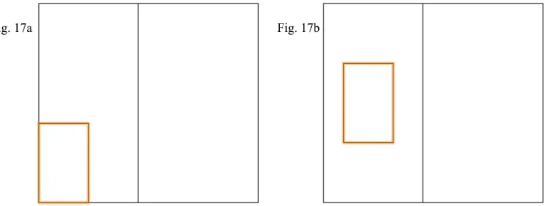
♢ Create a rectangle 2'6" wide by 4'0" tall representing a window opening aligned to the bottom left corner of the 5'0" wall. Move the
rectangle to the right X= 1'0" and up Y= 3'0".{Fig. 17 a & b}
Fig. 17a Fig. 17b
♢ Zoom-in on the window opening.
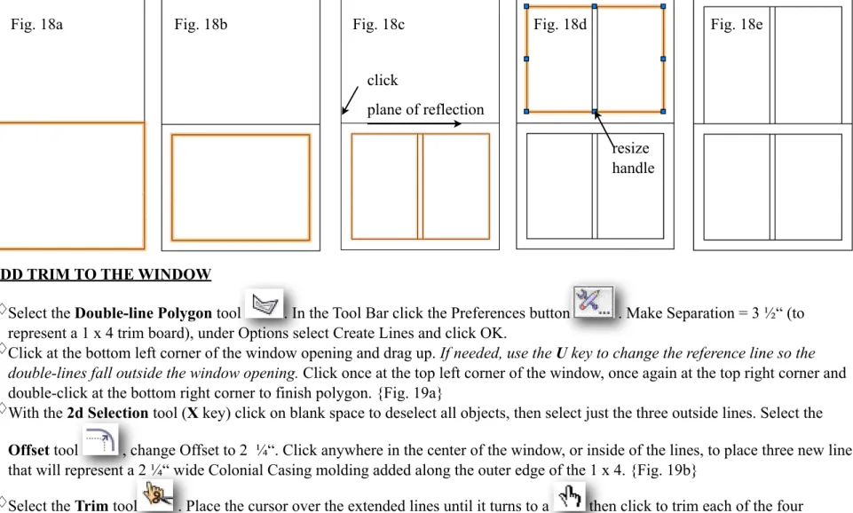
♢Use the Rectangle tool to draw the bottom sash inside the window opening that extends from the center to the bottom of the window.
Rely on the Screen Hints to tell you when you are snapped to the center of the window opening. {Fig. 18a}
♢With bottom sash still selected, select the Offset tool and in the Tool Bar select the Preference button . Under Offset
by Distance enter 2“.. Leave the other default settings and click OK. You can also enter 2” in the Distance field to right of the Preference button Place cursor inside of the rectangle and click to place a new rectangle that is 2” smaller than the original. {Fig. 18b} Use the Double-line tool with the reference line set to center to draw a vertical 1" wide mullion in the center of the bottom sash. Again, rely on the Screen Hints to tell you when you are snapped to the center of the sash rectangle.{Fig. 18c}
♢With the 2d Selection tool, select both the inside sash rectangle and the mullion. Select the Mirror tool . In the Tool Bar the
Mirror and Duplicate mode should be selected . Click once at the top corner of the outside sash rectangle and drag horizontally along top edge to establish the plane of reflection. {Fig. 18c} Click again to create a duplicate rectangle above the original.
♢With the 2d Selection tool, click in blank space to deselect all objects. Select the upper sash rectangle and drag its bottom center blue
resize handle down to resize it, so that its bottom line shares the top line of the lower sash. The cursor will change to a when you are snapped to a resize control point. Do the same with the center mullion. {Fig. 18d&e}
click
plane of reflection
Fig. 18a Fig. 18b Fig. 18c Fig. 18d Fig. 18e
resize handle
7) ADD TRIM TO THE WINDOW
♢Select the Double-line Polygon tool . In the Tool Bar click the Preferences button . Make Separation = 3 ½“ (to
represent a 1 x 4 trim board), under Options select Create Lines and click OK.
♢Click at the bottom left corner of the window opening and drag up. If needed, use the U key to change the reference line so the
double-lines fall outside the window opening. Click once at the top left corner of the window, once again at the top right corner and double-click at the bottom right corner to finish polygon. {Fig. 19a}
♢With the 2d Selection tool (X key) click on blank space to deselect all objects, then select just the three outside lines. Select the
Offset tool , change Offset to 2 ¼“. Click anywhere in the center of the window, or inside of the lines, to place three new lines that will represent a 2 ¼“ wide Colonial Casing molding added along the outer edge of the 1 x 4. {Fig. 19b}
♢Select the Trim tool . Place the cursor over the extended lines until it turns to a then click to trim each of the four
overlapping short line segments at the corners.
♢Select the Single Line tool and draw miter lines in the top right and left corners of the window trim. Hold down Shift key to
constrain angle to 45˚.{Fig. 19c}
!
Fig. 19a Fig. 19b Fig. 19c
♢Use the Rectangle tool to draw a 1 ½“ high window sill the width of the window casing. {Fig. 20a}
♢With the sill selected, in the Object Info palette (if not open under Window > Palette > Object Info) align the starting point to the
bottom center and in the Width field add + 2 after the 3‘1“ dimension. Vectorworks will do the math. Hit Return to extent the sill 2” wider than the window trim.{Fig. 20b }
♢With the sill still selected, duplicate it (zD). In the Object Info palette subtract 2” from its width, change its height to 3 ½“. Move
it to below the sill. {Fig. 20c}
Fig. 20a Fig. 20b Fig. 20c
8) ADD CURTAINS
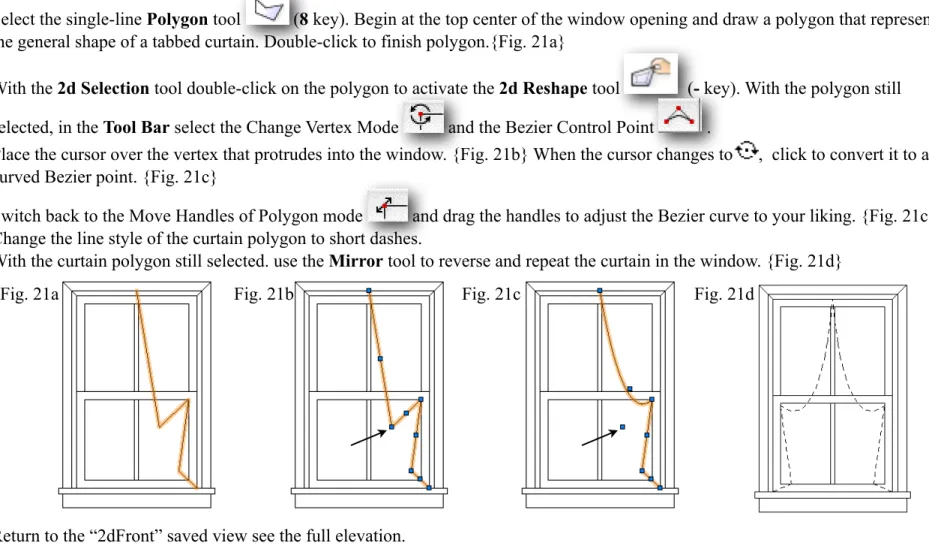
♢Select the single-line Polygon tool (8 key). Begin at the top center of the window opening and draw a polygon that represents
the general shape of a tabbed curtain. Double-click to finish polygon.{Fig. 21a}
♢With the 2d Selection tool double-click on the polygon to activate the 2d Reshape tool (- key). With the polygon still
selected, in the Tool Bar select the Change Vertex Mode and the Bezier Control Point .
♢Place the cursor over the vertex that protrudes into the window. {Fig. 21b} When the cursor changes to , click to convert it to a
curved Bezier point. {Fig. 21c}
♢Switch back to the Move Handles of Polygon mode and drag the handles to adjust the Bezier curve to your liking. {Fig. 21c} ♢Change the line style of the curtain polygon to short dashes.
♢With the curtain polygon still selected. use the Mirror tool to reverse and repeat the curtain in the window. {Fig. 21d}
Fig. 21b Fig. 21c Fig. 21d
Fig. 21a
♢Return to the “2dFront” saved view see the full elevation.
9) ADD DOOR
♢Zoom-in around the 6‘0“ wall elevation.
♢Create a door opening using the Rectangle tool to draw a rectangle 2‘10“ wide by 6‘8“ tall starting at lower left corner of 6'0" wall.
♢Move the door opening rectangle to the right, X= 1'9", Y = 0”. {Fig. 22}
Fig. 22
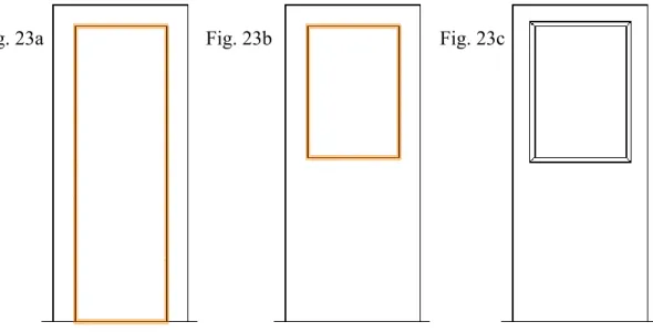
♢With the door opening rectangle still selected, duplicate it (zD). In the Object Info palette, with the starting point aligned to the
bottom center , subtract 5 ½“ from each side (2‘10“ - 11“) and the top (6‘8“ - 5 ½“). {Fig. 23a} Hit Return to set.
♢Change the align starting point to the top center and make the rectangle (door window opening) 3‘0“ high. {Fig. 23b}
♢With the rectangle still selected use the Offset tool to add 1 ¼“ wide molding to the outside of the window opening. Zoom in to add
miter lines in the corners. {Fig. 23c}
Fig. 23a Fig. 23b Fig. 23c
10) ADD ESCUTCHEON AND DOOR KNOB
♢ Zoom-in around the center right area of door where a doorknob would be.
♢Select the Rounded Rectangle tool . Draw a rectangle approximately 3" wide by 10" high. Find the radius handle on the
rectangle and move it around until you have the desired rounded rectangle shape. (You may have to change the Corner to Symmetrical in the Object Info palette.) {Fig. 24a}
♢Select the Circle tool (6 key)and in the Tool Bar select Circle by Diameter mode . Draw a 2 ¼“ diameter door knob
centered on the escutcheon. Add the key hole as an overlapping small circle and a rectangle filled with black. Nudge the objects into place using Shift/Arrow keys{Fig. 24b}
♢Select and Group the objects. Reposition the group so the center of the handle is on the bottom right corner of the door, then move
the group up 3‘0“ and to the left 2 ¼“ ( X = negative 2 ¼“, Y = 3‘0“) . {Fig. 24c}
Fig. 24a Fig. 24b Fig. 24c
11)ADD DOOR TRIM AND PANEL DETAIL
♢Repeat the same window trim procedure around door opening. {Fig. 25a}
♢Zoom-in around the lower half of door. Indicate the plinth blocks by drawing a horizontal line at the bottom of the vertical molding.
Move the line up 6". {Fig.25b}
♢ Use the Trim tool to click on and delete the center vertical line. {Fig. 25c} Repeat on the other side of the door. {Fig. 25d}
Fig. 25a
Fig. 25b Fig. 25c
Fig. 25d
♢Return to the “2dFront” saved view to see entire elevation.
12) ADD WALL MOLDING
♢Open the file “VWTutorialItems.vwx” you downloaded from the tutorial website. In the View Bar use the Design Layers menu to
make the “Molding” layer active . Select the cornice section and under Edit > Copy (zC).
♢Return to your project file under Window > “VWTutorial (your initials)”.
♢Zoom-in around top right corner of the 6‘0“ wall. Under Edit > Paste (zV). The pasted cornice section should appear either in the
center of the page or where you lasted clicked. Molding details were copied in full scale, but they will resize to the scale of the layer into which they are pasted. Reposition the cornice section so it aligns precisely with the top right corner of the wall. Change its fill to none. {Fig. 26)
Fig. 26
♢Go to the “2dFront” saved view. With the cornice section still selected, use the Mirror tool to reverse and repeat the section on the
other side of the 6‘0“ wall. A screen hint should indicate where the center is on the top of the 6‘0“ wall.
♢Duplicatethis section and move it to the top left corner of the 5’0” wall {Fig. 27} Zoom in to make sure corners align precisely.
Fig. 27
♢Select the left cornice section and the 5’0” wall together and under Modify > Add Surface (Shift/Option/zA) to create a solid
profile. The edges of the rectangle and section need to touch or overlap for the shapes to merge. {Fig. 28a&b}
Fig. 28a Fig. 28b
♢Scroll over to the center of the two walls. You can use the Space Bar to activate the Pan tool and click/drag the drawing across
the screen. Deselect all objects then select the center cornice section and the 6‘0“ wall and under Modify > Add Surface. Use the
Trim tool to delete line at the back of the cornice (which is actually the corner of the 5‘0“ wall).{Fig. 29a&b}
Fig. 29a Fig. 29b
♢Add the far right cornice section to the 6‘0“ wall.{Fig. 30a}
♢Draw three lines representing bottom and major divisions of the cornice profile. Length does not matter at this point. {Fig. 30b}
Fig. 30a Fig. 30b
♢Zoom out so you can view the top of both walls. Select the Connect and Combine tool . In the Tool Bar select the Single
Object Connect mode . Place the cursor on one of the lines until it highlights red. Click to select it, then click again anywhere on the left edge of the 5‘0“ wall, which will also highlight red, to extend the line to that boundary. Do the same for the other two lines. {Fig. 31} You may need to zoom in to select individual the individual lines. The page should automatically scroll when you move your cursor of the edge of the page. You can also click/drag the handle at the end of each line and resize it to the appropriate length.
Fig. 31
♢Repeat the procedure to place the baseboard section (from the VWTutorialItems file) at the bottom of the walls. Use the midpoint
screen hint for the wall, not the bottom center point on the door, when reverse and repeating the section with the Mirror tool on the 6‘0“ wall. Use the Trim tool to delete the lines that cross the door. {Fig. 32}
Fig. 32
♢Return to the “2dFront” saved view to see the full elevation.
13) CREATE SECTION VIEW OF WALL
♢In the Navigation palette, double-click on the Design Layers button to bring up the Organization window. Select New. Name
the new design layer “2dSection” and click OK. In the Navigation palette make sure Layer Options: Gray/Snap Others. {Fig. 33}
The lines on your drawing now should appear gray.
Fig. 33
♢ Select the Double-line tool . Use the Preferences Button in the Tool Bar to set the separation to 1" and select Create Polygons.
Draw vertical polygon to represent a section view of the wall flat that extends from the top to the bottom of the wall through the right half of the window. Change its fill to gray. {Fig. 34}
Fig. 34
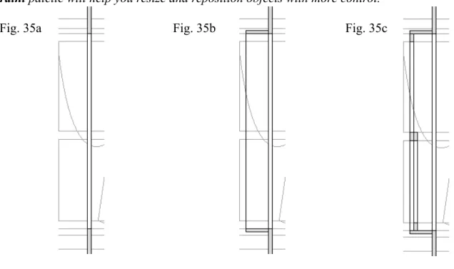
♢Zoom-in around the window. Draw a another 1” wide polygon over the wall section polygon representing the window opening.
Change its fill to white. {Fig. 35a}
♢Use the Rectangle tool to place a 5 ½“ wide vertical window reveal on the left side of the opening and add 3/4“ polygons
representing the top and bottom horizontal reveals. Set their fill to gray.{Fig. 35b}
♢Use the Double-line tool set to 1" thickness to draw two polygons within the window reveal rectangle that represent the top and
bottom overlapping window sashes. Add rectangles that represent cut-through sections of the sashes. Set their fill to gray. {Fig. 35c}
You may want to Zoom-in closer on these areas to ensure accuracy. You may find that turning off the Snap to Point constraint (Q key) in the Constraint palette will help you resize and reposition objects with more control.
Fig. 35a Fig. 35b Fig. 35c
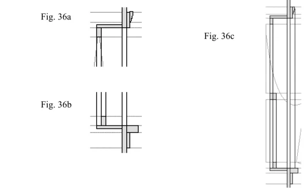
♢At the top of the window use the Rectangle tool to draw the trim section as a 3/4” wide by 3 1/2” (1x4) board. Add the window
casing section (from “VWTutorialItems.vwx) to the front of the 1x4. Change the fill of both to gray. {Fig. 36a}
♢ At the bottom of the window use the Rectangle tool to draw the sill section as a 2 1/2” wide by 1 1/2” tall board sitting on top of a
3/4” wide by 3 1/2” tall board. Change the fill of both to gray.{Fig. 36b}
♢Draw a vertical line representing the front of the trim from the Casing down to the the sill. {Fig. 36c}
Fig. 36b Fig. 36a
Fig. 36c
♢ Navigate to the top of the wall section.
♢ From the file “VWTutorialItems.vwx”, copy the cornice section and paste it at the top of the wall section. Change its fill to gray.
{Fig. 37a}
♢Duplicate the cornice section, move the duplicate to the right 1‘0“ and change its fill to none.
♢Use the Reshape tool and in the Tool Bar select the Hide or Show Edges mode . Click on center handle at the back of
the cornice section to hide the vertical line. {Fig. 37b}
♢Draw horizontal lines representing the major division in the molding. {Fig. 37c} ♢Do the same for the baseboard. {Fig. 37d}
Fig. 37b Fig. 37c Fig. 37d
Fig. 37a
♢Zoom out to view entire section. Draw a vertical line 1‘0“ to the right of the front edge of the wall section that connects the bottom
of the cornice section to the top of the baseboard section. Nudge it to the left about 1/4”. {Fig. 38a}
♢Under Edit > Select All (zA) Group them (zG). Drag the group of objects to the right of the drawing, holding down the Shift key
to constrain the movement horizontally, until the front edge of the return wall overlaps the door. {Fig. 38b}
♢ Draw a 1 ½“ wide rectangle on the front edge of the return wall representing the profile of the door trim. Zoom in and use the Trim
tool to delete the overlapping lines in the baseboard profile.{Fig. 38c}
Fig. 38a Fig. 38b Fig. 38c
♢Select the door trim rectangle. Under Edit > Cut (zX).
♢Select the section group and under Modify > Edit Group (z[) or double-click on any object of the group. ♢Under Edit > Paste in Place (z/Option V). Under Modify > Exit Group (z]).
♢Fit to Page Area (z4) ♢Save this view as “2dSection”.
14) DIMENSION, NOTATE AND ADD MOLDING DETAILS
♢Go to the “2dFront” saved view.
♢Under View > Create Viewport. Name it “vpFrontEl” and Create on Layer > New Sheet Layer. Make Sheet Title “FrontEl1/2”,
click OK, accept defaults and click OK. You should notice an orange boundary around your drawing, which is actually the viewport selected.
Note: You have just created the viewport “vpFrontEl”, which is a snapshot linked back to the design layer, “2dFrontEl”. Changes made in the design layer will automatically show in a viewport, but additions to a viewport will not show on the design layer. This viewport
currently is assigned to a particular sheet layer, “shtFrontEl1/2”, or a piece of paper with a particular size and orientation determined by using the page or print setup command. In the Object Info palette you can control various attributes of a viewport, i.e. its scale, visibility of various classes and layers, etc., which will not effect the original design layer. A viewport can appear on multiple sheet layers and have different attributes on each sheet layer.
Hint: Adding “vp” to the beginning of all viewport names is a personal organizational device I use to help distinguish viewports from the design layers, especially in more complex drawings with many more components.
♢With the FrontEl viewport selected, duplicate it (zD). A duplicate is placed on top of the original. You will not notice a change. In
the Object Info palette, click . Click in the columns next to the layer titles to make the 2dSection layer visible and the 2dFrontEl layer invisible. {Fig. 39a&b} The 2d FrontEl layer doesn’t seem to disappear because the original FrontEl viewport is still visible. Drag the new section viewport constrained horizontally to the open space on the right side of your page. {Fig. 39c}
Fig. 39a Fig. 39b Fig. 39c
♢Duplicate the section viewport and move it to the left in between the wall and the original section viewport. {Fig. 40a}
♢Double-click on any object in the duplicate section viewport to bring up the Edit Viewport window. Select Crop and click OK. ♢Zoom in around the cornice section and use the Rectangle Tool to draw a rectangle around it. All objects outside of the rectangle
should be grayed. The cropping object acts as a portal through which you see the desired portion of your design layer. You can use any single shape as a crop. When finished Exit Viewport Crop. The crop rectangle will become invisible unless you select “Crop Visible” in the Object Info Palette.{Fig. 40b}
♢With the viewport still selected, in the Object Info palette change its scale to 1-½“=1’-0”. {Fig. 40c}
♢Duplicate the cornice viewport. Double-click on it and select Crop. Drag the crop rectangle down and resize it, so it shows just the
upper window jam, casing, and sash. Exit Viewport Crop.
♢Duplicate this viewport and repeat procedure to create details for the bottom of the window and the baseboard. Reposition the detail
sections so they fit neatly within the space between the front elevation and the wall section. {Fig. 40d}
Fig. 40a Fig. 40b Fig. 40c Fig. 40d
♢Double-click on the any object in the front elevation viewport to bring up the Edit Viewport window. Select Annotations and click
OK. You are going to add dimensions and notations to the individual viewports on this particular sheet, leaving the original elevations free of clutter for other purposes.
♢ Under File > Document Settings > Document Preferences. Click the Dimensions Tab. Deselect “Associate Dimensions”, select
“Create dimensions in dimension class”, and under Dimension Standard select ASME. Click OK. This sets the default dimension style to the ASME standard. I suggest deselecting Associated Dimensions because they add complexity that isn’t useful in this project. ◇ Under Text > Format Text (z/ShiftT). Select a font of your choice and a 10 pt font size. Click OK. In the Attribute palette,
change the fill to solid white. This text format will remain the default for this drawing until you change it.
◇ Select the Constrained Linear Dimension tool (N key). In the Tool Bar select the Constrained Base-line Dimension mode . Begin with the vertical dimensions. Starting at the lower left corner point of the 5'0" wall click once to set the base line.
Notice cursor changes to . Move cursor up to the lower left corner of the window opening (top of the sill) and click. Move cursor away from the wall edge to establish the dimension offset and click. Then click the cursor at the top left of the window opening, and again to the top of the wall. Double-click to set the dimension and stop the chain. You may need to zoom-in on area of drawing to assure the extension lines of your dimensions are referencing the desired points.
Note: Use the sample project illustration at the end of the tutorial as reference for all dimensions and notation. Note: Use the X key to exit out of the Dimension tool.
* You can resize a dimension after it is placed by using the 2d Selection tool to select the dimension, then click/drag the handle where the extension line touches the object.
* You can adjust a dimesion by double-clicking on it and editing the text field.
* You can make the dimension a specified length after starting it by hitting the Tab key and using the X and Y fields in the Data Bar to enter the desired measurement.
* You can reposition the dimension text by using the 2d Selection tool to click/drag the text up or down along the dimension line. * You can alter the distance between the dimension line and the object by click/dragging where the arrow head meets the extension
line.
♢Repeat procedure to place the horizontal dimensions for each wall and the window and door openings. Make sure you reference the
edge of the wall, not the baseboard. You may need to return to the “2dPlan” view to move your plan farther away from the wall to make room for the horizontal dimensions. When finished with dimensioning, Exit Viewport Annotations. If your dimensions appear grayed, select the viewport and in the Object Info palette, click on the classes button and change the dimension class to visible.
Note: You may want to reposition your objects, or the entire drawing, on the page to allow more room for dimensions. For example: you want to move the entire drawing with all its viewports another foot or so farther to the right on your page. First Fit to Page Area (z4). Then select the Move Page tool (found under the Pan tool ). Click anywhere on the page (an X appears through page) and drag the page to its new location. Click again to set the new page position.
♢Double-click on the section viewport and select Annotate. In the Tool Bar, change back to the regular the Constrained Linear
Dimension mode and dimension the 1‘0“ return wall. Exit Annotate Viewport.
♢Double-click on each of the section details. Title and dimension and their main components. Note scale for details.
15) ADD LABELS, NOTES AND TITLE BLOCK
♢In the Navigation palette, double-click on the Classes button to bring up the Organization window. Select New and name the
new class “Notation” and under Creation Options make; Saved View Visibility for New Classes: Visible and Viewport Visibility for New Classes: Visible. Click OK. Click to the left of “Notation” to make it the active class. {Fig. 42} From now on, any object you create will be assigned to the active Notation class until you make a different class active, with one exception -- as you specified in the Document Preferences, dimensions are always assigned to the Dimension class.
Fig. 42
♢Double-click on the front elevation viewport and annotate it. Note the wall covering, window glazing and curtain fabric. Use the Text
tool (1 key) to label this view “FRONT ELEVATION” and in the Object Info palette, increase the font size to 12 pt, make it bold and underlined.
♢Create the section cutting plane using the Single Line tool to draw a vertical line through the 5'0" wall, toward the right side of the
window, extending a few inches past the top and bottom of the wall. In the Attributes palette Change its style to the "dash-dot-dot" style. Draw short lines, approximately 1'0" long, connected to the top and bottom points of the section line, pointing to the right.
Change their end points to solid arrows. Select all three lines and make them heavy (0.18). Label the arrows A and A’. Select all three lines with labels and group them (zG). Exit Annotate Viewport.
♢ Exit Annotation Viewport.
♢Annotate the section viewport. Label it “SECTION AA' ” with the same format as the FRONT ELEVATION label. Exit Annotate
Viewport.
♢Annotate and label each of the section details. In the baseboard detail, below the label add SCALE: 1 ½” = 1’-0” and reduce its font
size to 10 pt. Exit Annotate Viewport.
♢In the bottom right corner of your sheet, create a title block with the name of this project, the predominant scale:1/2”=1’-0”, your
name and date. Anything created on the sheet layer, rather than in a viewport, is full, 1:1 scale.Creating a stock title block in full scale will allow you to copy and paste it onto any sheet, regardless of the scale of the viewports.
♢ Double-click on the front elevation viewport and select edit Design Layer. Select the overall shapes of the two walls and the window
and door openings, and increase their line weight to a medium thickness (0.18). This will make the overall shape of the wall stand out.
♢ In the Navigation palette, click the Sheet Layers button . Control/click on “Sht-1:FrontEl1/2” and select Edit. Change the DPI to
300 and make sure your page is properly formatted and targeting your printer. Click OK.
♢To create a drawing without dimensions and notation for building a white model, in the Navigation palette, click the Viewports
button . Control/click on “Sht -1: FrontEl1/2” and Duplicate. Edit the Duplication and change the Sheet Title to “Front El 1/2” w/o notation.” Select each viewport and in the Object Info palette, click the button. Click in the middle of the Visibility column to make the Dimension and Notation classes invisible.
.
♢ Print your drawing.
Congratulations! You have completed the 2d drafting section of this tutorial. You are encouraged to make any alterations to the drawing you feel would more clearly communicate the information. The sections that follow will introduce you to very basic 3d modeling, texturing, lighting, and rendering capabilities of VectorWorks. To continue you will need to have the Spotlight version of Vectorworks and Renderworks installed.
16) BUILD 3D MODEL OF WALLS
♢In the View Bar use the Classes pop up window to make the None class active.
♢In the Navigation palette, double-click on the Design Layer button and create a new Design Layer, name it “3dModel” with a
scale of ½“ = 1‘ or 1:24. Click OK and make sure Gray/Snap Others is selected in the Layers Options.
♢In the Attributes palette set the default object fill to none.
♢In the Tool Sets palette, select and the [3d] Wall tool (9 key). In the Tool Bar select the Preference
button and make the Overall Thickness 6“. Although theatre walls/flats are typically 1” thick, the window and door reveals create the illusion they are thicker. In this project you are modeling the illusion.
♢Zoom in and trace over the three walls in the plan view. Double-click to end the wall.{Fig. 43} Use the U key to toggle the reference
line of the walls so they bottom edge of of the new 3d walls line up with the plan view. Use the Shift key to constrain.
Fig. 43
♢With the three walls still select, in the Object Info palette, make the Height to 10‘0“.
♢Now that you have 3d objects in your drawing, you can navigate among 3d orthographic views of your drawings three different
ways: 1) under View > Standard Views to select a 3d view; or 2) using the Current View button in the View Bar to select a 3d view; or 3) using the Numeric Keypad with 5 = top view, 2 = front view, 8 = back view, 4 &6 = side views, and 1,3,7,9 = isometric views. Experiment with these options.
♢Go to a Top/Plan view (z5). Zoom in on it and save this view as “3dPlanw/2d”.{Fig. 44a}
♢In the Navigation palette, change the Layer Options to Active Only. Save this view as “3dPlan.” {Fig. 44b}
♢Go to a front view (2 key). Center the image on your page and save this view as “3dFront”. {Fig. 44c} Go to a right view (6 key).
Center it and save this view as “3dRight”. {Fig. 44d} Go to a left isometric view (1 key). Center it and save this view as “3dIsoLft”.
{Fig. 44e}
Fig. 44a
Fig. 44b
Fig. 44c Fig. 44d Fig. 44e
♢Return to the “3dPlanw/2d” saved view and zoom in on the 5’ wall with the window.
17) ADD 3D WINDOW AND DOOR AND PLATFORM
♢ In the Building Shell tool set select the Window tool (Shift/Option W). Place cursor at the approximate bottom center of the
the window and double-click to place a window.The wall lines should highlight red to show that the window symbol will be inserted into the wall.{Fig. 45a} Select the 2d Selection tool or hit the X key to exit out of the Window tool. To adjust the position of the window after it is placed, use the Shift/Right or Left Arrows.
♢Return to the “3dFront” saved view. {Fig. 45b}
♢With the window still selected, in the Object Info palette, change the Sash Operation to Double Hung. Check that the Width = 2‘6“,
Height = 4‘0“. Make the Elevation = 3‘0“ with the Elevation Set at: Sill of the Window. Hit Return, Enter or Tab to set the change.
♢Further down in the Object Info palette, under Jamb and Sash, and check Use Wall Depth.
♢Further down, under Trim, select Include Interior Trim and make the width 3 ½“. Select Trim Under Stool {Fig. 45c&d} ♢Further down,under Muntins select Top and Bottom Sashes, Num V Muntins = 1, and Muntin Width = 1”.
Fig. 45b
Fig. 45c
Fig. 45d Fig. 45a
♢Return to the “3dPlanw/2d” saved view and zoom in around the 6’ wall with the door.
♢In the Building Shell tool set select the Door tool (Shift/OptionD). Place cursor at the approximate bottom center of the the
plan of the door and double-click to place a door.Again make sure the wall lines highlight red before double-clicking. Nudge the 3d door plan so it is centered over the 2d door plan {Fig. 46a}
♢Return to the “3dFront” saved view. {Fig. 46b}
♢In the Object Info Palette, make the Door Width = 2‘10“.
♢Further down under Jamb select Use Wall Depth, under Leaf select Leaf Type: Glass and make the Bottom Rail Width = 3‘0“, select
Include Interior Trim and make Width = 3 ½“.{Fig. 46c&d}
Fig. 46a
Fig. 46b
Fig. 46c
Fig. 46d
♢Go to the “3dIsoLft” saved view. {Fig. 47a}
♢Under View > Rendering > Unshaded Polygon. If your screen is wide enough, in the View Bar at the very right top corner you
will see the Rendering Mode button . Use it to choose Polygon > Unshaded. }
♢Select all three walls and in the Attributes palette change their fill to solid and pick a light value object fill color. Accept the prompt
to Render the layers if asked.
♢ Select both the door and window and change their fill to a medium value color. {Fig. 47b} Soon you’ll assign more specific surface
treatment to these objects.
Fig. 47a Fig. 47b
♢Go to the “3dplan” saved view. Zoom out. Use the Rectangle tool to create a 20‘0“ wide by 16‘0“ high rectangle to serve as a
platform. {Fig. 48a}
♢With the rectangle selected, under Model > Extrude. Make Extrusion = -1‘0“. The negative is important because it adds depth below
the ground plane. All 3d objects by default sit on the ground plane unless otherwise specified.
♢Go to a front view (2 key). Change the rendering mode back to Undshaded Polygon and assign a medium value color to the
platform. {Fig. 48c}
Fig. 48a Fig. 48b
18) ESTABLISH PERSPECTIVE VIEW AND ADD 3D BACKDROP
♢Change to a plan view (5 key) and zoom out a bit.
♢Under View > Set 3D View (z0). Click the cursor about 10‘0“ below the center of the platform (observation point) and click again
on the center of the platform (picture plane). {Fig. 49a} Set Viewer and Look Toward Heights at 6‘0“. Choose Normal perspective and click OK. {Fig. 49b & c} Don’t be concerned if your perspective view looks a little different than the example. You’ll now proceed to navigate in three dimensional space to adjust the view.
♢Fit to Page Area button (z4). Save this view as “3dPersp”. As you begin to explore the 3d navigation tools, you may get lost.
Use this view to return to a safe place.
Fig. 49b Fig. 49c
Fig. 49a
♢ In the Tool Sets palette select and the Walk Thru tool (Shift U). Place the cursor in the very
center of your drawing area, click/hold and drag slowly downward. You should notice the perspective view growing smaller as if the observer were walking away. Now move the cursor towards the top of the drawing to simulate the observer walking toward the objects. Try moving right and left. If you loose your image, or it becomes distorted as you explore with the Walkthrough tool, start over by going to the “3dPersp” saved view. Moving your scroll wheel or finger up & down on a scratch pad should also act like the Walk Thru too.
◇ Next select the Translate View tool (Shift V). Place the cursor in the center of your drawing area, click/hold and drag slowly up/down/right/left to reposition the view on the page. The translate tool moves the observer while maintaining the distance between the observer and the object being viewed.
♢Next select the Flyover tool (Shift C). Place the cursor in the center of your drawing area, click/hold and drag slowly up/down/
right/left to rotate the view on the center of the ground plane.
♢Resize and position your perspective view, so it almost fills the area within the brackets and is slightly offcenter.{Fig. 50a} ♢ Save the revised view as “3dPersp” and click OK to replace the existing saved view.
♢Go to the “3dPlan” saved view. Zoom out to include the platform. Resave this as “3dPlan” view.
♢At the back of the platform create a cyclorama by drawing a 2“ deep rectangle the width of the platform. Extrude it to 16‘0“ and
giving it a light lavender color. {Fig. 50b}
♢Return to the “3dPersp” saved view. {Fig. 50c}
Fig. 50b extruded
rectangle
Fig. 50a Fig. 50c
19) ADD 3D MOLDING
♢Go to the “VWTutorialItems” file. In the Molding layer select and copy the cornice and baseboard section.
♢Return to “YourTutorial” file. Go to the “3dPlan” saved view and paste the sections into a blank space below the plan. ♢Select the Polygon tool (8 key). Draw a polygon that around the perimeter of the wall unit (double-click to finish the
polygon) and move it (zM)below the plan 2‘0“, so you can see it more easily. {Fig. 51a}
♢Copy the polygon to use later.
♢Select both the polygon and the cornice section. Under Model > Extrude Along Path. Click the Prev/Next buttons until the polygon
is highlighted red. Click OK. {Fig. 51b}
Fig. 51a Fig. 51b
♢Control/click on the extruded cornice and choose edit profile. Move cornice section, so the top left corner is at the intersection of two
dotted lines, (0”,0” on the rulers). {Fig. 52a} Exit Extrude Profile.
♢Move the cornice unit up 2’0” back into its place on the wall plan. {Fig. 52b} Go to a side view and move the cornice unit up 10‘0“
to the top of the wall. {Fig. 52c}
Fig. 52a Fig. 52b Fig. 52c
♢Return to the “3dPlan” saved view and paste in paste the polygon path you had copied, or draw a new one. Repeat the Extrude Along
Path procedure with the baseboard section and edit the profile,so the bottom left corner of the section is at the intersection of the two dotted lines. Move the baseboard up 2’0” into position on the wall.
♢Go to the “3dfront” saved view. Draw a rectangle at the bottom of the doorway the width of the door with its molding, fully
overlapping the baseboard. {Fig. 53a} Extrude it 2‘0“.
♢Go to a plan view and move the extruded rectangle so it fully intersects the wall and baseboard. {Fig. 53b}
♢Go back to a front view, select both the rectangle and baseboard, under Model > Subtract Solids. Use the arrows to highlight the
baseboard (the object to be subtracted from) and click OK. {Fig. 53c}
Fig. 53a Fig. 53b Fig. 53c
♢While in a front view, use the Double-line Polygon tool to draw polygons with a 1 ½“ separation to create trim around the door
window. {Fig. 54a}
♢Extrude the polygon 3/4“ and go to a side view to move it to the front surface of the door. {Fig. 54b} ♢ Assign fill color of added molding the same blue fill as the door.
Fig. 54a Fig. 54b
♢From the file “VWTutorialItems.vwx”, go to the 3d Objects layer and copy the figure and chair.
♢Return to your file and paste them into a front view. Reposition them to sit on the top of the platform with the figure midstage right
and chair in the downstage left corner. Select the throne. Double-click the Rotate tool and rotate the chair -45˚.
♢Go to the “3dPersp” saved view. Change fill and color of the added units. {Fig. 54c}
Fig. 54c
20) ADD TEXTURE TO SURFACES
♢Under View > Rendering > Fast RenderWorks. Save this view as “3dRenderFast” Fast RenderWorks creates a quick interactive
rendering with simplified surface treatment and shadows. Shadows will show later when you add lights to your rendering.
♢ Under Window > Palettes check the Resources Browser to make it visible, if it isn’t already. In the Resources Browser, under
the Resources pop-up menu, select New Resource in “Your File” > Rendworks Texture. {Fig. 55} Fig. 55
♢Name the texture “FloorStones”. Under Shaders -- Color: Obj Attributes > Pavement, change Size to 5’0” and Preview Options -
Obj Size: to 10‘0”. Leave the other settings as is for now. Click OK. The Size relates to the scale of your drawing. The Obj Size determines the size of the texture sample in the preview Window. {Fig. 56}
. Fig. 56
♢With the 2d Selection tool, click on an edge of the main platform to select it. In the Object Info palette, click on the Render tab at
the top. Pull down the texture field and select “FloorStones” at the top of the list of textures. {Fig. 57a} Your model should rerender with a fieldstone floor. Rendering has to be set to one of the RenderWorks modes to view textures. {Fig. 57b}
Fig. 57a Fig. 57b
♢With the platform still selected, in the Object Info palette, click the arrow at the end of the texture field and choose Edit FloorStones
Resource. Click the Color: Pavement - Edit button and change the colors to make a warmer stone texture. Click OK.{Fig. 58}
Fig. 58
♢In the Resources Browser, create a NewRendworks Texture in “YourTutorialFile”. Name the texture “Wallpaper1”. Under Shaders,
Color: Obj Attributes > Image. Choose “wallpaper.jpg” downloadable from the tutorial website. Tile the image Horizontal and Vertical and click OK.
♢Change Size to 1’0” and Preview Object Size to 4‘0”. Leave the other settings as is for now. Click OK. {Fig. 59a}
Fig. 59a
♢In the View Bar, click the Classes button or double-click the Classes button in the Navigation palette. Create a new class titled
“Walls”. Under Creation Options make Saved View Visibility for New Class(es): Visible . Click OK{Fig. 59b} Fig. 59b
♢Under Tools> Organization make the “Walls” class active and click edit. {Fig. 59c} At the bottom of the Edit Class window assign
the Left, Center and Right components of the walls to the “Wallpaper1” texture from the pop up menu and check Use Textures at Creation. Click Ok. {Fig. 59d} Exit out of Organization window. VectorWorks walls have three distinct components -- front, back and middle which they they instead call left, center and right for some reason .
♢Go to the “3dPlan” saved view. Select all three walls. In the Object Info palette, click the Shape button and assign the walls to the
class “Walls.” {Fig. 59e} Fig. 59c
Fig. 59d Fig. 59e
♢Go to the “3dRenderFast” saved view to see the changes. You can now change the texture of all three walls at once by reassigning the
texture of the class “Walls.” {Fig. 60} Fig. 60
♢ In the Resources Browser, click on the Files arrow and Add New Favorite Files which will take you to the Textures folder within
the Libraries folder that comes with the VectorWorks application. If you haven’t yet downloaded the VW Libraries, under Help/
Download Content and follow instructions for Renderworks Libraries at least. Choose “Textures”/”Textures-Wood” Under the Files pop-up menu you should find the Textures Wood folder added to the list. Select it and you will see all the wood textures available. You may have to select “View as Thumbnails” in the Resources pop up menu. {Fig. 61a}
Fig. 61a Add New Favorite Files
List of Texture and Symbol Libraries now accessible View textures as Thumbnails and apply selected textures to selected objects
♢In the Resources Browser, under Render Textures scroll down to the Wood Panel thumbnails and double-click on a few textures of
your liking for the wall molding. (I choose Wood Panel Beech RT.) They will be that added to the texture menu in your file.
♢n the Resources Browser, in the Files pop up field, return to “VWTutorialYourName.” You should see the Wood Panel textures you
chose added your resources.
♢Select each the window, door, door panel trim, baseboard and cornice. In the Object Info, click the Render tab. In the Texture
pop-up menu assign them a wood texture of your choice. If you are having a difficult time selecting the door and window, in the Navigation Palette, make sure Class Options are set to Show/SnapModify Others.
♢Select the cornice and baseboard separately andin the Object Info palette change the Rotation to 90˚ so the grain runs horizontally.
{Fig. 61b}
Note: Changing the direction of the wood grain in the window and door is a much more complicated process because these units are composed of many different pieces.When you finish the tutorial, if you’re up to the task, in the Resource palette duplicate the Wood Panel . . . Texture, edit it to rotate the wood image 90˚. You’ll then need to create a new class called something like, BirchPanel Horizontal and another called BirchPanel Vertical with the appropriately oriented textures assigned to them. Control/click on the door or window, and choose Edit to bring up the Door or Window Settings window. At the bottom of the list on the left select Classes. You’ll see a list of all the components of that unit. Experiment assigning the components of the door to the appropriate component. This will be tedious and will only make a difference if you plan on rendering your wall up close.
♢Double-click on the chair to edit the group.
♢ Click on a thumbnail of a texture to select it and ether drag it on an object to apply the texture, or select an object, then a texture, and
under the Resources arrow choose apply. You may want to add Textures - Interiors to your favorites to increase your options for the chair upholstery. Experiment with the scale as well in the Object Info palette. Exit Group. {Fig. 61c}
Fig. 61b Fig. 61c