DESIGN AND IMPLEMENTATION
OF A SCSI TARGET FOR
STORAGE AREA NETWORKS
Ashish A. PalekarRobert D. Russell
TR 01-01
TABLE OF CONTENTS
TABLE OF CONTENTS ... II LIST OF FIGURES... V ABSTRACT...VI
INTRODUCTION ... 1
1.1 MOTIVATION AND GOALS FOR THIS THESIS... 1
1.2. RESOURCES USED... 1
1.3 ORGANIZATION OF THE THESIS... 2
SMALL COMPUTER SYSTEM INTERFACE ... 3
2.1 INTRODUCTION... 3
2.1.1 Reasons for SCSI ... 3
2.1.2 SCSI Terminology ... 3
2.1.3 SCSI Commands and their format... 4
2.2 SCSI TARGET MODEL... 8
2.3 BASICS OF SCSI TARGET OPERATION... 9
2.4 TASK MANAGEMENT FUNCTIONS... 11
2.4.1 Abort Task ... 11
2.4.2 Abort Task Set ... 12
2.4.3 Clear ACA ... 12
2.4.4 Clear Task Set ... 12
2.4.5 Logical Unit Reset ... 12
2.4.6 Target Reset ... 12
2.5 SCSI ERROR REPORTING... 13
2.5.1 The REQUEST SENSE command ... 13
2.5.2 Asynchronous Event Reporting ... 13
2.5.3 Autosense... 14
STORAGE AREA NETWORKS... 15
3.1 INTRODUCTION... 15
3.2 ISSUES WITH TRADITIONAL STORAGE... 15
3.3 APPROACHES TO SOLVING THE STORAGE BOTTLENECK... 16
3.4 THE STORAGE AREA NETWORK APPROACH... 16
SCSI TRANSPORT PROTOCOLS... 18
4.1 INTRODUCTION... 18
4.2 FIBRE CHANNEL... 18
4.2.1 Fibre Channel basics ... 18
4.2.2 SCSI over Fibre Channel ... 22
4.3 SCSI OVER ETHERNET... 24
4.3.1 SCSI Encapsulation Protocol... 24
4.3.2 Internet SCSI... 26
SCSI TARGET EMULATOR ... 30
5.1 INTRODUCTION... 30
5.2 PRELIMINARY DESIGN ISSUES... 31
5.3 DESCRIPTION OF API NEEDED... 32
USER-SPACE TARGET EMULATOR ... 35
6.1 OVERVIEW... 35
6.2 BASIC STRUCTURE OF THE USER SPACE TARGET EMULATOR... 35
6.2.1 I/O to and from a real disk drive... 36
6.2.2 I/O to and from a file that contains the logical blocks... 40
6.2.3 I/O to and from memory ... 40
6.3 DESCRIPTION OF THE FUNCTIONS AVAILABLE TO A TARGET FRONT-END... 41
6.3.1 Opening the SCSI device using open_SCSI_device() ... 41
6.3.2 Finding the buffer requirements using get_allocation_length()... 41
6.3.3 Calling handle_SCSI_cmd() to execute the command... 42
6.3.4 Closing the SCSI device using close_SCSI_cmd()... 43
6.4 DESIGN OF THE SEP USER-SPACE FRONT-END... 43
6.5 LESSONS LEARNED FROM THE USER SPACE TARGET EMULATOR... 45
DESIGN AND IMPLEMENTATION OF THE KERNEL SPACE TARGET EMULATOR... 46
7.1 INTRODUCTION... 46
7.2 ISSUES INVOLVED IN THE DESIGN OF THE SCSI TARGET MID-LEVEL... 46
7.3 OVERVIEW OF THE OPERATION OF THE SCSI TARGET SUB-SYSTEM... 48
7.4 SCSI TARGET MID-LEVEL TO FRONT-END TARGET DRIVER API ... 48
7.5 FRONT-END TARGET DRIVER TO SCSI TARGET MID-LEVEL API ... 54
7.6 SCSI TARGET MID-LEVEL DESIGN... 56
7.6.1 Registration and Deregistration with the mid-level ... 57
7.6.2 Processing of a READ-type command... 60
7.6.3 Processing of a WRITE-type command ... 62
7.6.4 Processing a Task Management function ... 62
7.6.5 Other design considerations ... 64
7.7 SCSI TARGET MID-LEVEL: MODES OF OPERATION... 64
7.7.1 I/O to and from memory ... 65
7.7.2 I/O to and from a file that contains the logical blocks... 65
7.7.3 I/O to and from a real SCSI disk... 65
7.7.3.1 I/O to and from a SCSI disk using the queuecommand interface ... 65
7.7.3.2 I/O to and from a SCSI disk using the scsi_do_req interface ... 67
7.7.3.3 I/O to and from a SCSI disk using the SCSI Generic interface... 67
7.8 IMPLEMENTATION OF THE SEP FRONT-END IN KERNEL SPACE... 68
7.9 IMPLEMENTATION OF THE FIBRE CHANNEL FRONT-END IN KERNEL SPACE... 68
7.10 IMPLEMENTATION OF THE ISCSI FRONT-END IN KERNEL SPACE... 69
TESTING AND PERFORMANCE ANALYSIS ... 71
8.1 OVERVIEW... 71 8.2 APPROACHES TO TESTING... 71 8.2.1 Conformance Testing... 71 8.2.2 Stress Testing ... 72 8.2.3 Interoperability Testing ... 72 8.2.4 Operability Testing... 72 8.3 PERFORMANCE ANALYSIS... 72
CONCLUSIONS AND FUTURE WORK ... 73
9.1 CONCLUSIONS... 73
9.2 FUTURE WORK... 74
9.2.1 Performance Analysis ... 74
9.2.2 Development of Testing Tools and Test Suites... 74
9.2.3 Protocol Development... 74
9.2.4 Kernel Design Projects ... 74
REFERENCES... 76
APPENDIX A... 78
APPENDIX B ... 79
APPENDIX C ... 80
LIST OF FIGURES
Figure 2-1: Representation of a typical SCSI system... 4
Figure 2-2: The READ(6) CDB... 5
Figure 2-3: SCSI Phase Sequences... 7
Figure 2-4: SCSI Client-Server Model ... 8
Figure 2-5: SCSI Target Hierarchy... 8
Figure 2-6: Structure of a Logical Unit... 9
Figure 2-7: The REQUEST SENSE command... 13
Figure 3-1: Concept of Storage Area Networks ... 16
Figure 4-1: Protocols providing a mapping of SCSI over different protocols ... 19
Figure 4-2: Fibre Channel Functional Levels... 20
Figure 4-3: A possible implementation of a Fibre Channel Network... 21
Figure 4-4: Functional Mapping between SCSI and Fibre Channel... 23
Figure 4-5: Relationship between SEP and the TCP/IP Protocol... 25
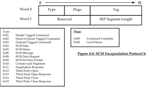
Figure 4-6: SCSI Encapsulation Protocol header ... 26
Figure 4-7: Generic iSCSI Message Header ... 28
Figure 5-1: Abstract Overview of the functionality of a Target Emulator ... 31
Figure 5-2: Functionality provided by the Target Emulator... 32
Figure 5-3: Organization of SCSI code in the Linux kernel... 33
Figure 5-4: API between the generic SCSI Target Mid-Level and the Front End Target Driver... 34
Figure 6-1: Functional Overview of the User Space Target Emulator ... 36
Figure 6-2: Implementation of the User Space Target Emulator ... 37
Figure 6-3: Definition of struct sg_header... 39
Figure 6-4: I/O using Vectors... 39
Figure 6-5: Definition of struct disk_properties... 42
Figure 6-6: Scsi_Host_Template used by the SEP Initiator ... 44
Figure 7-1: A Block View of SCSI Initiator and Target Sub-Systems... 47
Figure 7-2: Definition of Scsi_Target_Device... 50
Figure 7-3: Definition of Target_Scsi_Cmnd... 51
Figure 7-4: Definition of struct scsi_request... 52
Figure 7-5: Definition of Target_Scsi_Message... 54
Figure 7-6: Definition of Scsi_Target_Template... 54
Figure 7-7: A detailed view of the SCSI Target Emulator Implementation ... 58
Figure 7-8: Global Data Structure used by the STML ... 59
Figure 7-9: Registration of a Device with the SCSI Target Mid-Level... 60
Figure 7-10: Deregistration of Device(s) from the SCSI Target Mid-Level ... 60
Figure 7-11: Processing of a READ-type command ... 61
Figure 7-12: Processing of a WRITE-type command... 63
Figure 7-13: Processing of a Task Management function... 64
Figure 7-14: Options for I/O to and from a SCSI Disk ... 66
ABSTRACT
DESIGN AND IMPLEMENTATION OF A SCSI TARGET
FOR STORAGE AREA NETWORKS
by
Ashish A. Palekar
University of New Hampshire, May 2001
The Small Computer Systems Interface (SCSI) has been used to transmit data between applications (Initiators) and storage devices (Targets). One of the major limitations of SCSI has been the length of the SCSI bus. With the evolution of Storage Area Networks (SANs), several protocols have been proposed to extend the length of the SCSI bus e.g., Fibre Channel, SCSI Encapsulation Protocol (SEP), and Internet SCSI (iSCSI). The evaluation of these technologies requires the use of an Initiator and a Target that implement the said protocols. A large portion of what such Initiators or Targets need to do from a SCSI perspective can be isolated into a logical code unit referred to as a mid-level. While there exists in the Linux kernel a generic SCSI Initiator mid-level that drivers written for various Initiators can interface with, no corresponding facility exists for the Target side. This thesis involves the development of a Generic SCSI Target mid-level for Linux along with implementing front-end drivers for Fibre Channel, SEP and iSCSI that can utilize the said Target mid-level. Other uses for the Target Emulator are as a bridge between two protocols and as an interface for SAN Management.
CHAPTER 1
INTRODUCTION
1.1
Motivation and Goals for this Thesis
The past few years have seen a tremendous growth in the amount of traffic on the Internet. An increase in the number of people with access to the Internet has meant that the Internet has become a viable pathway for trade and related commerce activities. Increasingly, mission-critical applications are being put on the Internet. This increase in traffic over the Internet has meant an exponential growth in the data that needs to be stored. Access to this data has become a critical resource and traditional server-based approaches to data access indicate this as a potential bottleneck in the very near future. This has led to the emergence of the concept of Storage Area Networks (SANs) where SCSI (Small Computer System Interface) is used to exchange data between an application (Initiator) and the storage device (Target).
Fibre Channel was one of the first protocols designed with the idea of SANs in mind. Interoperability issues and incompatibility with existing infrastructure has led to the development of several different protocols in place of Fibre Channel with the objective of transmitting SCSI data over existing TCP/IP networks. The evaluation of these protocols requires an Initiator and a Target that can transmit SCSI data using the said low-level protocols. A good way in which this can be achieved is by isolating the common portions of what these Initiators and Targets need to do in terms of a logical unit of code that is responsible for processing SCSI commands, data and responses. To adapt this unit of code to a specific SCSI Transport Protocol, a relatively simpler front-end driver can be written that handles the details of the SCSI Transport Protocol itself. Thus, an Initiator or a Target driver for a SCSI transport protocol would consist of two portions – a common SCSI processing portion which would be common to all SCSI Transport Protocols and a second portion specific to the SCSI Transport Protocol. The common SCSI processing portion is referred to as the SCSI mid-level (for reasons explained in Chapter 5) whereas the latter is referred to as the front-end driver. The Linux kernel has existing support for SCSI Initiators in terms of a SCSI Initiator mid-level (SIML). Such a mid-level does not exist for SCSI Targets. This thesis aims at developing a SCSI Target mid-level (STML) for the Linux kernel. Three front-end Target drivers will be written to interface with this SCSI Target mid-level implementing the SCSI Encapsulation Protocol (SEP), the Internet SCSI (iSCSI) and Fibre Channel SCSI Transport Protocols.
1.2. Resources
Used
The major resource used for this project is a Fibre Channel card. For the purposes of this project, QLogic Corporation made two ISP2200 A cards available. The facilities to test the implemented code are available through the InterOperability Lab, University of New Hampshire.
The ISP 2200 card is a 64-bit PCI to Fibre Channel card capable of operating at 33 and 66 MHz PCI. The cards support up to 200 MB/s Fibre Channel data transfer rates in full duplex. It
Initiator and Target operation. A description of the firmware support for the QLogic ISP 2200 A card is described in Appendix C.
The SCSI Initiator driver for the ISP 2200 A card was written by Chris Loveland, University of New Hampshire. This driver was used as a basis for developing the Fibre Channel Target driver. This Target driver interfaces with the SCSI Target Mid-Level. Xyratex Corporation has implemented a Target Emulator using the QLogic 2200 card for the Windows Operating system with the intent of using it as a testing tool. No access is currently available to this testing tool. Matthew Jacob of Feral Inc. (http://www.feral.com), has written an Initiator and Target driver for ISP 2100/2200/2200 A for various flavors of Unix. The Target driver written by him has a section of code that can be isolated as a SCSI Target mid-level. This code has been looked at and it is not functional on Linux. No attempt has been made at debugging this Target driver.
The drafts of the relevant SCSI ([1], [13], [14], [16]) and Fibre Channel ([2], [3], [15]) standards are available at the IOL. In addition, access to the draft standards is provided via the websites of the respective standards bodies (http://t10.org and http://www.t11.org). The relevant SEP draft [9] and the corresponding iSCSI draft [7] are available at the IETF (http://www.ietf.org) website.
1.3
Organization of the Thesis
Chapter 2 explains the SCSI protocol, detailing the issues involved with special emphasis on the operational details necessary from the point of view of a SCSI Target. Chapter 3 of this Thesis explains the concept of Storage Area Networks, the emergence of this concept and the enabling factors. Chapter 4 deals with SCSI Transport Protocols such as Fibre Channel, SEP and iSCSI. This chapter tries to detail the aspects that make these protocols unique and in conjunction with Chapter 2 helps to isolate the needs of a SCSI Target mid-level and any front-end driver. Chapter 5 details the design of a SCSI Target Emulator. It starts with the design of the SIML in the Linux kernel, rationalizes the design of a Target Emulator based on the inferences from the previous chapters and finally presents applications relevant to a SCSI Target Emulator. Chapter 6 deals with the user space implementation of the SCSI Target Emulator whereas Chapter 7 deals with the corresponding kernel space implementation along with the implemented front-ends. Chapter 8 presents basic testing and performance analysis performed on the three implementations and the corresponding front-ends more with an objective to get an “order of magnitude” idea about I/O rates. Chapter 9 summarizes the work done, and the conclusions drawn along with work that can be done in the future.
CHAPTER 2
SMALL COMPUTER SYSTEM INTERFACE
2.1 Introduction
Small Computer System Interface (SCSI) originated from the Selector Channel on IBM-360 computers, and was later scaled down by the Shugart Associates Company to make a universal, intelligent disk drive interface. It was called the Shugart Associates Systems Interface (SASI). SCSI became an ANSI standard in 1986. SCSI is an intelligent, parallel peripheral bus, with medium-to-high performance. SCSI is both a bus hardware specification and a command set to optimize the use of that bus. Over time, the SCSI standards have grown to recognize several devices - magnetic disks drives, tape drives, printers, scanners, processors, communications devices among several others. SCSI speeds now range from 1 MB/s to 160 MB/s.
2.1.1 Reasons for SCSI
Prior to the development of SCSI, for each new peripheral that was added to a given computer system, the computer had to be specially configured to manipulate the hardware in order to accomplish the task of reading and writing data to and from the device. This implied that more often than not, by the time the hardware and software design of the computer was complete, a new generation of peripherals was usually available. Thus, the peripherals attached to a computer were often a generation or more behind the computer itself.
The basic premise of SCSI is to give the computer complete device independence. In other words, all magnetic devices appear identical to the system except for their total capacity. All printers are identical as are all CD-ROMs. With SCSI, the system should not need any modification when replacing a device from one manufacturer with that from another manufacturer. The major implication for the development cycle therefore, is that the developer no longer has to write a new I/O driver for a brand new peripheral. The onus of being able to manipulate the peripheral specific hardware shifts from the host system to the peripheral device. As a result, development cycles are significantly reduced.
2.1.2 SCSI Terminology
There are two kinds of devices on the SCSI bus: the SCSI Initiators – which start the I/O process and the Targets - which respond to a request to perform an I/O process. The traditional ‘master’ and ‘slave’ functions switch back and forth between Initiators and Targets. The single-byte (Narrow) SCSI bus supports up to eight devices whereas the 16-bit Wide SCSI bus supports 16 devices. For any given set of interconnected devices, there must be at least one device capable of providing the functionality of an Initiator and at least one other capable of providing the functionality of a Target.
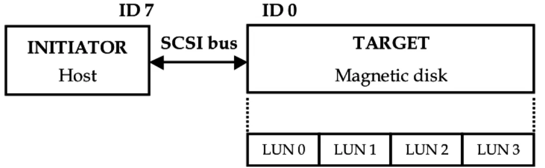
Each Target device can also be subdivided into several Logical Units (LUNs – explained later). A representation of a SCSI system is shown in Figure 2-1. It is also possible to connect several computers, each with one or more SCSI host adapters, to a shared peripheral, such as a SCSI scanner. The maximum number of SCSI devices (each of these devices having a SCSI_ID) on a single-byte SCSI is eight. In addition to this, each of the devices, except the Initiator, can have up to eight logical units (LUNs). This brings the theoretical maximum number of devices/LUNs on the eight-bit SCSI bus to 57 (1 Initiator + 7 Targets x 8 LUNs).
Figure 2-1: Representation of a typical SCSI system
A further level of abstraction is achieved in SCSI with the introduction of the concept of Logical Block Addressing. If a computer needs access to data, it is addressed in terms of a certain Logical Block Address (LBA). The Initiator does not need knowledge about the physical geometry or details about the layout of the drive in question. In this sense, a logical address is very similar to the concept of a virtual address. In other words, an Initiator issues commands directed to a specific set of LBAs. The Target upon receiving commands converts the LBAs into actual information about the track, cylinder head and the sector address. With some loss of efficiency, LBAs provide a uniform means for the Initiator to refer to the Targets. The mechanism of addressing is made device-independent. The Initiator uses the READ CAPACITY command in order to determine the maximum LBA on a magnetic disk as well as the size of one Logical Block.
2.1.3 SCSI Commands and their format
A SCSI command is generated by the Initiator (on the host) and is sent to the Target during the command phase (described later). A command and its parameters are sent as a block several bytes long called the Command Descriptor Block (CDB). SCSI commands can be classified into three types of commands based on the length of their CDBs:
Group – 0 uses 6-byte CDBs - 1, 2 uses 10-byte CDBs - 5 uses 12-byte CDBs
Command groups 3 and 4 are reserved, whereas command groups 6 and 7 are vendor-specific. SCSI was initially designed for magnetic disks which in the late seventies had relatively small capacities compared with those available today. Thus, transfer sizes could be adequately expressed in one byte - as a result, the Group-0 commands were sufficient. The 10-byte and 12-byte CDBs were added for the vastly expanded capacities of present day devices.
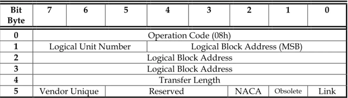
An example of a SCSI command is the READ(6) command [14]. The CDB for the READ(6) command is shown in Figure 2-2. The first byte of the CDB is the Operation Code (OP Code). A
INITIATOR
Host
TARGET
Magnetic disk
LUN 0 LUN 1 LUN 2 LUN 3
ID 7
ID 0
SCSI bus
INITIATOR
Host
TARGET
Magnetic disk
LUN 0 LUN 1 LUN 2 LUN 3
ID 7
ID 0
SCSI bus
list of OP Codes and the corresponding command names is shown in the Appendix A. It is followed by the LUN in the upper three bits of the second byte, and by the LBA and transfer length fields (READ and WRITE commands) or other parameters. The last byte of each CDB is the Control byte. This byte contains two important bits, the LINK and the Normal ACA. The LINK bit is used to continue a Task across multiple commands whereas the Normal ACA bit is used to control the rules for handling error conditions created by the failure to execute a command.
Bit
Byte 7 6 5 4 3 2 1 0
0 Operation Code (08h)
1 Logical Unit Number Logical Block Address (MSB)
2 Logical Block Address
3 Logical Block Address
4 Transfer Length
5 Vendor Unique Reserved NACA Obsolete Link
Figure 2-2: The READ(6) CDB
The READ(6) command requests that the Target transfer data to the Initiator. The current data values contained in the addressed logical block on the Target’s storage device, shall be returned to the Initiator that transmitted the READ(6) command.
The Logical Block Address field specifies the logical block at which the READ operation shall begin. The transfer length field specifies the number of contiguous logical blocks of data to be transferred. A transfer length of zero indicates that 256 logical blocks shall be transferred. Any other value indicates the number of logical blocks that shall be transferred. The typical size of a logical block is 512 bytes, although it can be any multiple of 512 bytes (This value is obtained from the response to the READ CAPACITY command – described earlier).
The execution of SCSI commands can be thought of in terms of phases. The SCSI architecture includes eight distinct phases:
a. BUS FREE phase:
The BUS FREE phase indicates that there is no current I/O process and that the SCSI bus is available for a connection
b. ARBITRATION phase
The ARBITRATION phase allows one SCSI device to gain control of the SCSI bus so that it can initiate or resume an I/O process. Priority is given in accordance with device IDs. Higher IDs have higher priority. On the WIDE SCSI bus in SCSI-3, the low-byte Ids have higher priority over high-byte IDs. This is to allow the 8-bit devices to be always recognized by all other devices.
c. SELECTION phase
The SELECTION phase allows an Initiator to select a Target to initiate some Target function (e.g., READ or WRITE command).
d. RESELECTION phase
The RESELECTION phase is an optional phase that allows a Target to reconnect to an Initiator for the purpose of continuing some operation that was previously started by the Initiator but was suspended by the Target (i.e, the Target disconnected by allowing a BUS FREE phase to occur before the operation was complete).
e. COMMAND phase
The COMMAND phase allows the Target to request command information from the Initiator.
f. DATA phase
The DATA phase consists of both the DATA IN and the DATA OUT phase. The DATA IN phase allows the Target to request that data be sent to the Initiator from the Target. The DATA OUT phase allows the Target to request that data be sent from the Initiator to the Target.
g. STATUS phase
The STATUS phase allows the Target to request that status information be sent from the Target to the Initiator.
h. MESSAGE phase
The MESSAGE phase consists of both a MESSAGE IN, and a MESSAGE OUT phase. Multiple messages can be sent during either phase. The first byte transferred in either of these phases shall be either a single-byte message or the first byte of a multiple-byte message. Multiple-byte messages shall be wholly contained within a single message phase. The MESSAGE IN phase allows the Target to request that messages be sent from the Target to the Initiator. The MESSAGE OUT phase allows the Target to request that messages be sent from the Initiator to the Target. The Target invokes this phase when the ATN (Attention) condition is invoked by the Initiator.
The last four phases are collectively referred to as the Information Transfer phases. The SCSI bus can never be in more than one phase at any given time. Typically, the Information Transfer phases are implemented in software whereas the first four are implemented in hardware. Furthermore, these hardware phases can be implemented in an interconnect-specific manner. Thus, SCSI leaves open to the protocols used by the low-level interconnect the method for how to select a Target and how to decide if the Target and the Initiator are ready for data transfer.
In addition to these phases, SCSI also defines two conditions: the Attention condition and the Reset condition.
The Attention condition allows an Initiator to inform the Target that the Initiator has a message ready. The Target may get this message by performing a MESSAGE OUT phase.
The Reset condition is used to clear all SCSI devices from the bus. This condition shall take precedence over all other phases and conditions. Any SCSI device may create the reset condition. The BUS FREE phase always follows the Reset condition. The effect of the Reset condition on the I/O processes that have not completed, SCSI device reservations, and the operating mode of SCSI device is determined by whether the SCSI device has implemented the hard reset alternative or the soft reset alternative (one of which shall be implemented). The hard and soft reset alternatives are mutually exclusive within a system.
A SCSI device that implements the hard reset alternative, upon detection of the Reset condition shall:
a. Clear all I/O processes including queued I/O processes. b. Release all SCSI device reservations.
c. Return any SCSI device operating modes to their appropriate original conditions (similar to those conditions that would have been found after a power-on). MODE SELECT conditions shall be restored to their saved values if there have been saved values. In the absence of saved values, the default values are used.
d. Unit attention condition shall be set.
A SCSI device that implements the soft reset alternative, on the other hand, shall:
a. Attempt to complete any I/O processes that have not completed, and that were fully identified.
b. Preserve all SCSI device reservations.
c. Preserve any SCSI device operating modes (MODE SELECT, PREVENT/ALLOW MEDIUM REMOVAL commands, etc)
d. Preserve all information required to continue normal dispatching of I/O processes queued prior to the reset condition.
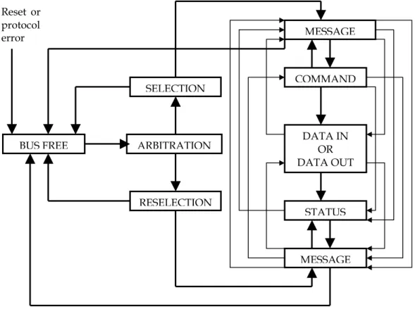
The order in which phases are used on the SCSI bus follows a prescribed sequence. The Reset condition can abort any phase. It is always followed by the BUS FREE phase. In addition, any other phase can be followed by the BUS FREE phase but quite a few such transitions are the results of error conditions. The normal sequence of phases as described by the standards is depicted in Figure 2-3.
Figure 2-3: SCSI Phase Sequences BUS FREE MESSAGE MESSAGE STATUS COMMAND DATA IN OR DATA OUT RESELECTION ARBITRATION SELECTION Reset or protocol error
2.2
SCSI Target Model
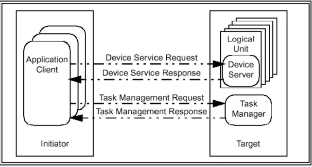
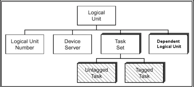
A Target is composed of a Target Identifier, a Task Manager, and one or more Logical Units. A Target Identifier is a field containing up to 64 bits that is a SCSI device identifier for the device. Every Initiator references a Target using the Target Identifier. The process of assignment of a Target Identifier is beyond the scope of SCSI. A Task Manager is a server that controls one or more tasks in response to task management requests (discussed in a following section). There is one Task Manager per SCSI Target device. A basic Logical Unit consists of a Logical Unit Number, a Device Server and one or more Task Sets (see Figure 2-6).
Figure 2-4: SCSI Client-Server Model
The basic structure of a SCSI sub-system is as shown in Figure 2-4. Each SCSI Target device provides two types of services, device services executed by the LUNs under the control of the Device Server and Task Management functions performed by a Task Manager. The abstract model of a SCSI Target is shown in Figure 2-5.
Figure 2-6: Structure of a Logical Unit
The structure of the Logical Unit is depicted in Figure 2-6. A basic Logical Unit consists of a Logical Unit Number, a Device Server and one or more Task Sets. A Logical Unit may contain a dependent Logical Unit (such as the one shown in Figure 2-6). The Logical Unit Number serves as an external identifier used by an Initiator to identify a Logical Unit within the Target. All SCSI Targets shall accept LUN 0 as a valid address to execute SCSI CDBs. The Device Server is responsible for executing the SCSI commands and manages a Task Set according to the rules established by SCSI. A Task Set is composed of at most one Untagged Task or a combination of zero or more Tagged Tasks. A Tag is an identifier (assigned by the Initiator) to uniquely identify a Task within a Task Set. Accordingly, a Task with a Tag assigned to it is referred to as a Tagged Task; otherwise, it is referred to as an Untagged Task. The composition of a Task includes a definition of the work to be performed by the Logical Unit in the form of a command or a group of linked commands. Each Task is uniquely identified by a Task Identifier.
2.3
Basics of SCSI Target Operation
Between a power-on and the time that it is selected, SCSI Targets should be able to respond with appropriate status and sense data to the TEST UNIT READY, INQUIRY, and REQUEST SENSE commands. All SCSI Targets are required to support, in addition to the above commands, the SEND DIAGNOSTIC command. These commands are used to configure the system, to test devices, and to return important information concerning errors and exception conditions.
The Target model [16] (Section 2-2) tries to minimize the amount of state information resident in a Target. The ideal Target model emphasizes maintaining information with respect to outstanding commands only. The Initiator-Target pair can be thought of in terms of a client-server pair in which the Initiator client makes requests which are responded to by the Target server. There are significant benefits in trying to minimize the amount of information that resides on the server. The most obvious one is that of trying to prevent the Device Server on the SCSI Target from becoming the bottleneck device. Furthermore, maintaining the state information almost entirely on the Initiator enables SCSI Targets to rely on the Initiator to initiate the recovery process when the execution of a SCSI command has failed. Although there are a large number of commands which are a part of SCSI, there is a smaller sub-set which represents commands that are required.
The SCSI Architecture Model ([1], [16]) describes the transmission, processing and completion of SCSI commands in terms of remote procedure calls. Thus, for example, an application client invokes the following remote procedure in order to execute a SCSI command:
Service response = Execute Command (Task Address, CDB, [Task Attribute], [Data-Out Buffer], [Command Byte Count], [Autosense Request] || [Data-In Buffer], [Sense Data], Status);
where:
INPUT PARAMETERS:
Task Address: A representation of the Initiator port responsible for this command along with the Target id and LUN to which this command is transmitted CDB: The SCSI command which is to be executed
Task Attribute: Nature of the Task (Simple, Ordered, Head of Queue, ACA)
Data-Out Buffer: Buffer containing command specific information such as data or parameter lists needed to execute the command
Command Byte Count: The maximum number of bytes to be transferred by the command
Autosense Request: Argument requesting the return of automatic sense data when the execution of the SCSI command fails
OUTPUT PARAMETERS:
Data-In Buffer: Buffer containing command specific information returned by the LUN Sense Data: A buffer containing sense data returned by the LUN by means of an
autosense mechanism
Status: A one-byte field containing command completion status Service Response assumes one of the following values:
TASK COMPLETE: indicating that the command was completed
LINKED COMMAND COMPLETE: LUN response indicating that a Linked Command was successfully completed
SERVICE DELIVERY or TARGET FAILURE: Command execution has been ended because of a device malfunction or a service delivery failure
The SCSI protocol is thus specified in terms of function calls. The specifics of how these functional calls are implemented are not specified. For example, the Execute Command function call is specified. However, SCSI does not specify the actual mechanism to get the corresponding command and data (if any) to the Target. This has interesting implications. Foremost amongst these is that SCSI can be easily adapted to any interconnect (referred to as the low-level interconnect) since SCSI leaves it up to the interconnect and the protocol used by the interconnect (referred to as the low-level protocol) to decide how it (the low-level interconnect) provides the functionality requested by the remote procedure. Furthermore, SCSI only specifies the commands and the expected responses to those commands. This implies that the low-level interconnect has a great amount of freedom about how it chooses to get the required information across from the Initiator to the Target and vice versa (depending on the direction of data flow required by the command).
The Client/Server mechanism used by SCSI affects the mode of functioning of Initiators and Targets. When an Initiator (the Client) issues a command, the data buffers required by the command are already allocated (for a READ or for a WRITE – typically by the user space application on the Initiator that is responsible for the READ or WRITE) when the command is transmitted to the Target. As a result, before the Initiator issues a READ to the Target, the buffer to receive the data corresponding to the READ is already allocated. An Initiator thus, does not need flow control mechanisms for READ or WRITE type commands.
A SCSI Target, on the other hand, has to be prepared to receive commands at any point in time. For a SCSI Target, SCSI READs are not a problem. The READ command is received by the Target, the buffers are allocated, the command is executed and the buffers are filled. Since the Initiator already has the buffer space allocated to receive the data for this command, the Target is free to send the buffers across to the Initiator. Thus, a Target does not need any flow control mechanisms for READ type commands (similar to an Initiator). In the case of a SCSI WRITE, the situation is a lot different. The Target receives the WRITE command. The direction of the data flow is from the Initiator to the Target. The Target does not have know the size of the data buffer it should expect to receive from the Initiator until it receives the WRITE command. In other words, the buffers to receive this data are not pre-allocated. This implies that the Initiator cannot automatically send the data associated with the WRITE command until the Target has allocated the necessary buffer space and informed the Initiator about it. Most low-level interconnects recognize this and provide a flow-control mechanism for the transfer of SCSI data from Initiator to the Target. For example, in the Fibre Channel protocol, the Target transmits a XFER_RDY (discussed later) to inform the Initiator about what portion of the data to send (The XFER_RDY frame gives a starting LBA and the number of bytes to be sent). Thus, transmitting a response to a WRITE command involves three steps on the Target:
1. Allocating the data buffers, which is independent of the low-level protocol
2. Informing the Initiator about what data it should send, which is specific to the low-level protocol
3. The execution of the command when the data arrives, which is again independent of the low-level protocol.
This imposed order has to be accounted for in the design of a SCSI Target.
2.4
Task Management Functions
Task Management functions provide an Initiator with a way to explicitly control the execution of one or more tasks. Each Task Management function represents a service requested by the Initiator, typically used to recover a Target from what an Initiator perceives as an error condition with the Target. The SCSI Target returns a response which signifies either that the requested function was completed, or that the function was rejected or that there was a service delivery/Target failure causing the command not to be delivered. Each SCSI protocol standard defines the actual events comprising each of the above service responses. The following are the Task Management functions that have to be provided by SCSI Targets:
1. Abort Task 2. Abort Task Set 3. Clear ACA 4. Clear Task Set 5. Logical Unit Reset 6. Target Reset
These are described below. The symbol ‘||’ in the expressions below implies that the parameter is required only if relevant.
2.4.1 Abort Task
Service Response = Abort Task (Task Address ||);
This function is required to be supported by a LUN if it supports tagged tasks and is optional for LUNs that do not support tagged tasks. The Task Manager shall abort the specified task if it exists. Previously established conditions (such as Auto Contingent Alliance, reservations etc.) shall not be affected. The Target, if it supports Abort Task, guarantees that no further responses
2.4.2 Abort Task Set
Service Response = Abort Task Set (Logical Unit Identifier ||); This function is required to be supported by all LUNs. The Task Manager, upon receiving the Abort Task Set, shall terminate all the Tasks in the Task Set created by the Initiator. This is equivalent to performing a series of Abort Task requests. Previously established conditions as well as Task Sets created by other Initiators shall not be affected.
2.4.3 Clear ACA
Service Response = Clear ACA (Logical Unit Identifier ||);
This function is only to be implemented by those LUNs that accept a Normal ACA (NACA) bit value of 1 in the CDB Control Byte (Refer to Section 2.1.3 and Figure 2-2). The Initiator invokes Clear ACA to clear an auto contingent allegiance condition from the Task Set serviced by the LUN.
2.4.4 Clear Task Set
Service Response = Clear Task Set (Logical Unit Identifier ||); This function is required to be supported by all LUNs that support Tagged Tasks and is optional for those that do not. All tasks in the appropriate task shall be aborted. No status shall be sent for any task affected by this request. A Unit Attention command shall be generated for all Initiators with aborted tasks (if any). When reporting the Unit Attention condition, the additional sense code shall be set to “Commands Cleared by Another Initiator”.
2.4.5 Logical Unit Reset
Service Response = Logical Unit Reset (Logical Unit Identifier ||); This function shall be supported by all LUNs that support hierarchical Logical Units (Refer to Section 2-2) and is optional for non-hierarchical Logical Units. To execute a Logical Unit Reset, the LUN shall:
1. Abort all tasks in its task set(s)
2. Clear an auto contingent allegiance (NACA = 1) or contingent allegiance (NACA = 0) condition, if one is present.
3. Release all reservations established using the reserve/release management method (persistent reservations shall not be affected)
4. Return the operating mode of the device to the appropriate initial conditions, similar to those conditions that would be found following a device power-on.
5. Set a Unit Attention condition
6. Initiate a Logical Unit Reset for all dependent LUNs
2.4.6 Target Reset
Service Response = Target Reset (Target Identifier ||);
This function shall be supported by all Target devices. Upon receiving a Target Reset Task Management Function, the Target device executes a Target hard reset. The definition of Target Reset events is protocol and interconnect-specific. Each SCSI Transport protocol is required to define the response to a Target Reset and the conditions under which it shall be executed. To execute a hard reset, a Target shall initiate a Logical Unit Reset for all attached LUNs (Refer to Section 2.4.5).
2.5
SCSI Error Reporting
In the event a command completes with a Check Condition status or other error conditions, SCSI requires that a Logical Unit make sense data available to the Initiator. The format, content and conditions under which sense data shall be prepared by a LUN are specified by the SCSI Architecture Model-2 (SAM-2), SCSI Primary Commands-2 (SPC-2), SCSI Block Commands-2 (SBC-2) and applicable SCSI Transport protocol standard.
Sense data may be transferred to an Initiator through one of the following methods: 1. The REQUEST SENSE command
2. An asynchronous event report 3. Autosense delivery
These three methods are discussed below.
2.5.1 The REQUEST SENSE command
The REQUEST SENSE command (shown in Figure 2-7) requests that the device server transfer sense data to the application client. The details of the appropriate response to the sense command are described in SPC-2 and have not been presented here for reasons of brevity.
Bit Byte 7 6 5 4 3 2 1 0 0 Operation Code (03h) 1 Reserved 2 Reserved 3 Reserved 4 Allocation Length 5 Control
Figure 2-7: The REQUEST SENSE command
2.5.2 Asynchronous Event Reporting
Asynchronous Event Reporting is used by a LUN to signal another device that an asynchronous event has occurred. The mechanism automatically returns sense data associated with the event. Each SCSI Transport protocol is required to define a mechanism for Asynchronous Event Reporting, including a procedure whereby an Initiator can selectively enable or disable asynchronous event reports from being sent to it by a specific Target. Support for Asynchronous Event Reporting is optional for a LUN.
Asynchronous Event Reporting is used to signal another device (usually an Initiator) that one of the following events has happened:
a. An error condition has occurred after command completion b. A newly initialized device is available
c. Some other type of Unit Attention condition has happened d. An asynchronous event has occurred
2.5.3 Autosense
Autosense is the automatic return of sense data to the application client coincident with the completion of a SCSI command. The return of sense data in this manner is equivalent to an explicit command from the application client requesting sense data immediately after being notified that an ACA condition has occurred. Although inclusion of autosense support in a SCSI Transport protocol is optional, most protocols support it, primarily as it eliminates one additional transaction between an Initiator and a Target. The application client may request autosense service for any SCSI command and provided it is supported by the protocol and the LUN, the device server shall return sense data if the command completes with a status of Check Condition. If autosense is requested and the protocol or the LUN do not support autosense, the device server should indicate that no sense data was returned. The application client may then issue a REQUEST SENSE command to retrieve sense data.
CHAPTER 3
STORAGE AREA NETWORKS
3.1 Introduction
The last decade has seen a change in the way data is perceived. Data is now viewed as a commodity, access to which, in many cases, determines the success or failure of a business. Compounded by changing computing technologies and the globalization of business via the Internet, there has been a tremendous increase in storage requirements. In addition, because of the desired economies of scale achieved by 24 x 7 x 365 businesses, the windows of time available for data backup and recovery have virtually disappeared. In a nutshell, this has led to the need for cost-effective ways to ensure high data availability and reliability.
3.2
Issues with traditional Storage
The numerous manifestations of SCSI (SCSI-2, Wide SCSI, Fast SCSI, and SCSI-3) have long been the interface of choice for high-speed computer-to-storage connectivity for Windows NT and Unix users. A study by International Data Corporation estimates that the cost of managing storage is 10 times the initial cost of the storage device. Furthermore, the challenges facing “data administrators” are:
1. Deploying vital applications across a network
2. Allowing pooled data to be shared simultaneously among a large number of users, who may be widely separated from each other
3. Managing storage distributed across a wide area as effectively and efficiently as possible, without expending large sums of money or manpower
4. Supporting growing number of data-intensive applications The problems with using traditional SCSI to solve the above problems are:
1. SCSI was designed as a point-to-point, directly attached computer-to-storage device interface. It is, therefore, ill suited for multiple host-to-storage communications.
2. The SCSI maximum of 15 devices is a restriction for companies that want to implement multiple servers to multiple storage devices networking architectures.
3. The maximum point-to-point distance allowed by SCSI is 25 m. For Ultra SCSI, this distance is reduced to 12 m. This distance limitation imposes architectural constraints on how storage is organized and distributed.
4. The point-to-point limitation of SCSI requires backup traffic from server-to-server to travel over the LAN thereby placing additional strain on the LAN.
3.3
Approaches to solving the Storage Bottleneck
The basic approach to solving the problem of the storage bottleneck deals with separating massive direct-access storage devices from the computer systems that access it. There are two mechanisms to achieve this. These are:
1. Network Attached Storage (NAS) 2. Storage Area Networks (SAN)
The NAS approach was the more traditional approach. It intercepts the communication between an application client and a storage device. Communication between the host and the remote storage is via a special file system that uses the traditional network protocol stack. Access to the storage device is controlled by means of the NAS Server. Communication between the NAS server and the storage device is by traditional channel protocols such as SCSI. The communication between the NAS Server and the host (NAS Client) uses a special (typically, messaging) protocol. The unit of access between the NAS Server and the NAS Client is a file. The NAS File System therefore has to deal with such issues as integrity, security, and consistency at the level of a file. An example of a NAS is the Network File System (NFS) from Sun. The problem with this approach is a lack of scalability. In addition, this approach requires a lot of manual intervention in terms of making the connected systems aware of any new storage resources or configuration changes.
3.4
The Storage Area Network Approach
The concept that emerged out of the NAS approach was the need to have a block level protocol controlling access to the data storage units. Another key concept that simultaneously emerged was the creation of a network that was solely dedicated to the task of managing and controlling access to a set of storage devices. The unit of access across this Storage Area Network (SAN) is a block. SCSI provides an interoperable, high-performance block level protocol. Any new block level protocol would have had to deal with many of the same problems that SCSI had already dealt with. Thus, instead of reinventing the wheel, current SANs use the SCSI protocol as the block level access protocol. However, to counter the limitations of SCSI, most notably distance, SCSI is transported over a different low-level protocol that controlled access to the shared medium. This is the concept behind SCSI Transport Protocols. The visualization of the SAN in relation to the traditional LAN has been shown in Figure 3-1.
A SAN is thus a dedicated network that connects different kinds of storage – such as tape libraries and RAID systems - to servers. Because stored data does not reside on any network server, server resources can be utilized for other purposes, increasing network capacity. The benefits of such an approach to storage are listed below:
1. Storage Consolidation: SANs enable consolidation of storage into a shared, heterogeneous, highly available environment. This is compared to the distributed “islands” of storage that foster unmanaged and unplanned growth.
2. Improved Management: The consolidated storage means improved management of storage. SANs help simplify administration and reduce management costs. Separating storage and server functions allows network administrators to view these two functions independently, and to divide bandwidth optimally between them.
3. Availability: A SAN can provide the ability to access the same storage over multiple paths. This implies that if one server or an interconnecting path fails, the user can access data through other paths. This is especially important for backup operations that rely heavily on successful operation.
4. Scalability: Since there is separation between the servers and storage, all the individual components of a SAN scale well. As additional secondary devices are added to the SAN, they too become accessible from any server within the network. Consequently, an organization can start with the system capacity it currently needs and add storage as and when needed in the future.
5. Bandwidth: SANs enable effective use of the bandwidth. Since, storage is tied to a network, and not to a server, the server can operate faster, and at a lower level of utilization. This implies that servers can operate faster and therefore, respond to requests quicker.
CHAPTER 4
SCSI TRANSPORT PROTOCOLS
4.1 Introduction
Chapter 3 presented the limitations of SCSI and how the concept of SANs has evolved around SCSI but using a different low-level interconnect to transmit SCSI over greater distances and to a greater number of devices than is allowed by traditional SCSI. The SCSI standards organization
(http://t10.org) has defined a set of protocols which allow SCSI to be transmitted over different
low-level interconnects. These are collectively called the SCSI Transport protocols. With the growing importance of SANs over the past couple of years, several approaches have been proposed to the IETF and to T10. Examples of such approaches would be:
1. Fibre Channel (FC)
2. Scheduled Transfer Protocol (STP)
3. SCSI Encapsulation Protocol (SEP) – Proposed by Adaptec
4. Internet SCSI (iSCSI) – Proposed by IBM originally – now on the IETF Standards Track 5. Storage Over IP (SoIP) – Proposed by Nishan Systems – now on the IETF Standards
Track
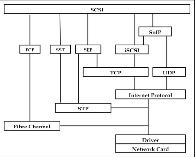
The hierarchy of these standards/proposals is shown in Figure 4-1. Some of these options are discussed.
4.2 Fibre
Channel
Fibre Channel is a serial, high-speed data channel that provides logical bi-directional service between two ports. Fibre Channel is directed towards unifying LAN and channel communications by defining an architecture with enough flexibility and performance to satisfy both sets of requirements. Fibre Channel presents one solution to achieving most of the requirements of the SAN. It essentially assumes an error free network. Fibre Channel can provide data access at 1 Gbps and 2 Gbps with 10 Gbps expected in the future.
4.2.1 Fibre Channel basics
Individual nodes on a Fibre Channel network are referred to as ‘N_Ports’. Each N_Port resides on a hardware entity. A port capable of providing switching capabilities is referred to as an F_Port. Fibre Channel is structured as a set of hierarchical functions as shown in Figure 4-2. Each of these functions is described as a level.
The Physical interface (FC-0) consists of transmission media, transmitters, and receivers and their interfaces. The Physical interface specifies a variety of media, and associated drivers and receivers capable of operating at various speeds.
The FC-1 level specifies the 8B/10B transmission code that is used to provide DC balance of the transmitted bit stream, to separate transmitted control bytes from data bytes and to simplify bit, byte and word alignment. In addition, the coding provides a mechanism for detection of some transmission and reception errors.
The FC-2 Level is the signaling protocol specifying the rules, and provides mechanisms needed to transfer blocks of data end to end. FC-2 defines functions and facilities available for use by the upper levels.
FC-3 provides a set of services that are common across multiple N_Ports of an FC node. This level is not yet well defined, due to limited necessity for it, but the capability is provided for future expansion of the architecture.
The FC-4 level provides mapping of Fibre Channel capabilities to pre-existing Upper Level Protocols, such as IP, SCSI, ATM, etc.
Figure 4-1: Protocols providing a mapping of SCSI over different protocols
UDP
TCP
Internet Protocol
Driver
Network Card
SCSI
SEPiSCSI
SoIP
STP
Fibre Channel
SST FCPFigure 4-2: Fibre Channel Functional Levels
IPI3 SCSI IP ATM Others
Upper Level Protocols
Common Services
Provision for services common to a group of nodes
FC-3 Level Upper Level Protocol Mapping
Mapping of ULP functions and constructs over FC delivery service FC-4 Level
Signaling protocol
Mapping of ULP functions and constructs over FC delivery service
FC-2 Level Link Services
Definition of Login and Logout protocols, and protocols for Sequence and Exchange Management, determination of Sequence
and Exchange Status
FC-0 Level Media
Optical or electronic cable plant, connectors Physical Interface
Transmitters and receivers, Link Bandwidth Transmission Protocol
8B/10B encoding, Ordered Sets, Error Monitoring, Port States
FC-1 Level Arbitrated Loop Functions
Ordered Sets for Loop arbitration, Fairness management,
Loop Initialization, Loop Address Assignment Arbitrated Loop
IPI3 SCSI IP ATM Others
Upper Level Protocols IPI3
IPI3 SCSISCSI IPIP ATMATM OthersOthers
Upper Level Protocols
Common Services
Provision for services common to a group of nodes
FC-3 Level Common Services
Provision for services common to a group of nodes
FC-3 Level Upper Level Protocol Mapping
Mapping of ULP functions and constructs over FC delivery serviceUpper Level Protocol Mapping FC-4 Level Mapping of ULP functions and constructs over FC delivery service FC-4 Level
Signaling protocol
Mapping of ULP functions and constructs over FC delivery service
FC-2 Level Link Services
Definition of Login and Logout protocols, and protocols for Sequence and Exchange Management, determination of Sequence
and Exchange Status Signaling protocol
Mapping of ULP functions and constructs over FC delivery service
FC-2 Level Link Services
Definition of Login and Logout protocols, and protocols for Sequence and Exchange Management, determination of Sequence
and Exchange Status
FC-0 Level Media
Optical or electronic cable plant, connectors Physical Interface
Transmitters and receivers, Link Bandwidth Media
Optical or electronic cable plant, connectors Physical Interface
Transmitters and receivers, Link Bandwidth Transmission Protocol
8B/10B encoding, Ordered Sets, Error Monitoring, Port States
FC-1 Level Arbitrated Loop Functions
Ordered Sets for Loop arbitration, Fairness management, Loop Initialization, Loop Address Assignment
Transmission Protocol
8B/10B encoding, Ordered Sets, Error Monitoring, Port States
FC-1 Level Arbitrated Loop Functions
Ordered Sets for Loop arbitration, Fairness management,
The FC-1, FC-2, and FC-3 levels are typically implemented in hardware whereas the FC-4 level is implemented in software.
A Fibre Channel network can be set-up in three basic topologies:
1. Point-to-Point topology: Here two N_Ports are directly connected to each other. It is a non-blocking connection.
2. Fabric Topology: A network of multiple N_Ports is connected to a switched network by means of an F_Port. The basis for this non-blocking network is to take advantage of the fact that devices cannot sustain high rates of transfer over long periods. Such a configuration allows for fewer interconnects and makes the Fibre Channel network extensible.
3. Loop Topology: The Loop topology consists of a maximum of 127 participating ports on one Loop. There is one link bandwidth that is shared between all ports. The Loop topology provides for a blocking and non-meshed network. Ports participating on the Arbitrated Loop are referred to as L_Ports (NL_Ports and FL_Ports).
An implementation of a Fibre Channel network can consist of a combination of these topologies. This is shown in Figure 4-3. Most devices tend to support multiple topologies. Ports on such devices are referred to as Fx_Ports (if they provide Fabric functionality) or Nx_Ports otherwise. Fibre Channel supports five Classes of Service. These Classes of service are distinguished primarily by the methodology with which the communication circuit is allocated and retained between the communicating Nx_Ports and the level of delivery integrity required for an application. Classes 1, 2, and 3 are topology independent. If the Fabric is not present, the service is provided as a special case of point-to-point. Classes 4 and 6 require functionality outside of the participating Nx_Ports. Fabrics and Nx_Ports are not required to support all Classes of service.
Figure 4-3: A possible implementation of a Fibre Channel Network FL_Port F_Port F_Port FL_Port
FL_Port N_Port NL_Port NL_Port NL_Port NL_Port N_Port NL_Port FL_Port F_Port F_Port F_Port F_Port FL_Port FL_Port NL_Port NL_Port N_Port NL_Port
1. Class 1 service - Dedicated Connection: Class 1 is a service that establishes Dedicated Connections. Once established, a Dedicated Connection is retained and guaranteed by the Fabric. This service guarantees maximum bandwidth available between two N_Ports across the established connection. In Class 1, frames are delivered to the destination N_Port by the Fabric in the same order as they are transmitted by the source N_Port. 2. Class 2 service - Multiplex: Class 2 is a connectionless service multiplexing frames at frame
boundaries. Multiplexing is supported from a single source to multiple destinations and to a single destination from multiple sources. There are no guarantees for in-order delivery of frames. Furthermore, there is notification of delivery or failure to deliver. 3. Class 3 service - Datagram: Class 3 is a connectionless service with unacknowledged
delivery. There is no notification of delivery or failure to deliver and any error recovery is performed by the Upper Level Protocol (ULP) level. Any acknowledgement of Class 3 service is left up to and determined by the ULPs. The transmitter transmits Class 3 Data frames in sequential order within a given Sequence. However, there are no guarantees for in-order delivery of frames. In Class 3, the Fabric is expected to make a best effort to deliver the frame to the intended destination and does not issue a busy or a reject frame to the source N_Port if unable to deliver the frame.
4. Class 4 service - Fractional Bandwidth: Class 4 is a service that uses a virtual circuit established within a Fabric and between two communicating Nx_Ports to transmit frames to each other using a fabric-managed fractional bandwidth allocation protocol. This service requires a Fabric. The transmitter transmits Class 4 Data frames in a sequential order within a given Sequence. In Class 4, frames are delivered to the destination N_Port by the Fabric in the same order as they are transmitted by the source Nx_Port. The Fabric or destination Nx_Port guarantees notification of delivery or failure to deliver in the absence of link errors. In case of link errors, notification is not guaranteed since the Source_Identifier (S_ID) may not be error free.
5. Class 6 - Multicast Connection: Class 6 allows an Nx_Port to establish simultaneous Dedicated Connections with multiple Nx_Ports. Once established, these Dedicated Connections are retained and guaranteed by the Fabric. This service guarantees maximum bandwidth available from the source N_Port to each destination N_Port across the established connections. The effective bandwidth of any Class 6 connection is multiplied by the number of destination Nx_Ports. Class 6 is inherently unidirectional. Data flows only from the source Nx_Port to the destination Nx_Ports. All destination Nx_Ports respond with the appropriate Link_Response frames to a Multicast Server. The Multicast Server collects the Link_Response frames and returns a single Link_Response frame to the source Nx_Port. Frames are delivered to the destination Nx_Ports by the Fabric in the same order as they are transmitted by the source Nx_Port. This service requires a Fabric.
The Login protocol allows devices to communicate the Classes of Service that they support to each other. Class 3 is the most common Class of Service.
4.2.2 SCSI over Fibre Channel
Fibre Channel has been designed to implement the prerequisites required by the SCSI Architecture Model (SAM). Thus, it provides a logical means for extending the SCSI bus. The basic synergy between Fibre Channel and SCSI is that Fibre Channel allows SCSI-3 compliant devices to communicate over a reliable Fibre Channel interface over a greater distance and at a greater throughput than would have been possible by the use of SCSI. Thus, Fibre Channel provides a reliable interconnect with SCSI serving as the Upper Level Protocol.
The mapping of SCSI into Fibre Channel is defined by the Fibre Channel Protocol for SCSI standard (X3.269 – 1995 revision 12) – also referred to as SCSI-FCP. Four kinds of functional management functions are defined by SCSI-FCP:
· Device Management
· Task Management
· Process Login/Logout Management
· Link Management
The FCP device and the task management protocols define the mapping of the SCSI functions defined in SAM to FC-PH. The SCSI-FCP is based on a two-level paradigm. The SCSI I/O Operation is mapped into an Exchange. The Request and Response primitives required by the I/O Operation are mapped into information units each of which may be contained within a Sequence. Link control is performed by the standard FC-PH protocol. This mapping is shown in Figure 4-4.
SCSI function FCP equivalent
I/O Operation Exchange
Request/Response Primitives Sequence
Command service request Unsolicited Command IU (FCP_CMND) Data delivery request Data descriptor IU (FCP_XFER_RDY) Data delivery action Solicited data IU (FCP_DATA) Command service response Command status IU (FCP_RSP)
Figure 4-4: Functional Mapping between SCSI and Fibre Channel
An application client begins an FCP Operation when it provides to the FCP a request for an Execute command service. A single request or a set of linked requests may be presented to the software interface of the FCP. Each request contains all the information necessary for the execution of one SCSI command, including the local storage address and characteristics of the data to be transferred by the command. The FCP then uses the services provided by Fibre Channel in order to execute the command.
The SCSI Initiator for the command starts an exchange by sending an unsolicited command Information Unit (IU) containing the FCP_CMND payload, including some command control flags, addressing information, and the SCSI command descriptor block (CDB). In particular, the FCP_CMND payload is the Execute Command service request and starts the FCP I/O operation. The exchange is identified by its fully qualified exchange identifier which is used exclusively for all IUs associated with the execution of the command request.
Upon receiving a SCSI command, the SCSI Target interprets the command. If a SCSI WRITE is requested, the SCSI Target determines the amount of data transfer required and allocates the necessary buffers to receive the data. It then transmits a data descriptor IU containing the FCP_XFER_RDY payload to the Initiator to indicate which portion of the data is to be transferred. The SCSI Initiator then transmits a solicited data IU to the Target containing the FCP_DATA payload requested by the FCP_XFER_RDY payload. If, on the other hand, the SCSI command received described a SCSI READ operation, the SCSI Target determines the amount of data transfer requested and allocates the necessary buffers. The data is then transferred using a solicited FCP_DATA IU to the Initiator. Data delivery requests continue until all data described by the SCSI command is transferred in either case. Thus, FCP_XFER_RDY are used to transfer
After all the data has been transferred, the device server transmits the Execute command service response by requesting the transfer of an IU containing the FCP_RSP payload. That payload contains the SCSI status and if an unusual status has been detected, the SCSI REQUEST SENSE information and the FCP response information describing the condition. The command status IU terminates the command. The SCSI logical unit determines if additional commands will be performed in the FCP I/O Operation. Upon determining that the command executed is the last or the only one to be executed in the FCP I/O Operation, the FCP I/O Operation and the exchange are terminated.
When the command is completed, returned information is used to prepare and return the Execute command service confirmation to the software that requested the operation. The returned status indicates whether the command was successful. The successful completion of the command indicates that the SCSI device performed the desired operations with the transferred data and that the information was successfully transferred to or from the SCSI Initiator. If on the other hand, command execution was unsuccessful, then the required error information can be provided according to a defined protocol.
If the command is linked to another command, then the FCP_RSP contains the proper status indicating that another command will be executed. The Target presents the FCP_RSP in an IU that allows command linking. The Initiator continues the same exchange with an FCP_CMND IU, beginning the next SCSI command.
FCP allows full use of Fibre Channel and the Classes of Service provided by it as well as the different topologies allowed by it.
4.3
SCSI over Ethernet
The development of Fibre Channel led to the birth of the concept of Storage Area Networks. The concept of SANs extends beyond the use of Fibre Channel as a lower level interconnect. The next logical step is to try and rationalize existing network infrastructure to serve the storage needs of organizations. Towards this end, there are several proposals to try to transmit SCSI over the existing Ethernet infrastructure. Most of these protocols use the TCP/IP protocol. Thus, these protocols are extensible to all link-level technologies that support TCP/IP.
The intrinsic issues that network-based technologies need to solve are those of reliability and Target identification. The latter translates into routing. This is solved by using the IP layer for routing. One can visualize a network cloud where Target devices are identified by an IP address. The reliable delivery is solved by having a reliable connection-oriented protocol on top of IP such as that provided by TCP. The advantages of this approach are manifold. The first issue is the ability to use existing network protocol stacks for transmission of data. The second advantage is that these protocols are well understood. The effects and implications of time-outs and window sizes have been studied in detail. Thus, a vast knowledge base is already available when considering the implementation of any protocol on top of the TCP/IP protocol suite. The use of Ethernet also keeps the costs low as it is the most widely deployed LAN technology and Ethernet components enjoy the benefits that come with the high volume. The following sections discuss the proposed protocols which transmit SCSI over Ethernet.
4.3.1 SCSI Encapsulation Protocol
The SCSI Encapsulation Protocol (SEP) was developed by Adaptec Inc [9]. This protocol was primarily intended as a proof of concept demonstration to be able to use network technology to create a high performance storage subsystem. The SEP Protocol assumes an underlying reliable