I
n the past few years, increasing volumes of computer viruses and corresponding attacks have emerged, and they’re likely to get worse. Cryptography and other technical security measures such as firewalls and in-trusion detection systems (IDS) can solve a variety of se-curity-related problems, but they work properly only if the underlying computing platform—specifically, the op-erating system—is secure. Unfortunately, most comput-ing platforms suffer from various security problems owcomput-ing to their architectural weaknesses and complexity.To address these issues, the computing industry has in-vested in trusted computing, a new generation of com-puting platforms based on improved hardware and software architectures. In particular, two well-known ini-tiatives from the Trusted Computing Group (TCG; https://www.trustedcomputinggroup.org), an alliance of leading IT enterprises, and Microsoft have emerged. No technical specifications for Microsoft’s Next Generation Secure Computing Base (NGSCB; www.microsoft. com/resources/ngscb/default.mspx) are available yet, but the TCG has published hardware specifications for its Trusted Platform Module (TPM; https://www.trusted computinggroup.org/faq/TPMFAQ/). Essentially, the TCG advocates using a secure hardware device to both verify the boot sequence and authenticate this verification. The TPM is a special chip embedded in a smart card sol-dered to the motherboard. Basically, the TPM is a micro-controller that stores keys, passwords, and digital certificates. Security processes, such as digital signatures and data de-cryption, are protected through the secure TPM subsystem. Today, TPM is available in some computers but not all of them, which underscores the need for an additional way to provide two-factor authentication prior to
boot-ing the operatboot-ing system. In our lab,
we’ve explored using a U-Key for trusted computing, both as a general design and as a real prototype. The user controls the U-Key (which is a smart card with a USB in-terface), and because it’s external to the TPM or any other integrity system, more than one U-Key can be used on the same platform (thus different users can have different loader, operating system, and application soft-ware configurations). The U-Key approach gives plat-forms that don’t have an installed TPM some of the benefits of TPM-like integrity checks.
The U-Key approach
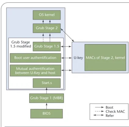
Our use of the U-Key approach is designed both to pro-vide boot integrity and to enforce access control. The basic idea is that the host computer actually boots from a USB disk loaded with the operating system and the loader. Figure 1 shows how we use a U-Key with a mod-ified Grand Unmod-ified Bootloader (Grub; www.gnu.org/ software/grub/) to get a trusted boot process; in our scheme, the U-Key is an extended smart card device with a USB interface.
Due to its size, Grub boots in stages. Stage 1 is the main boot record (MBR), which merely loads the next stage. Stage 1.5 is also quite small, but it can understand file systems. Depending on what file system holds the Stage 2 loader, Grub uses a different Stage 1.5—it’s even optional in some circumstances. Stage 2 is the meat of the loader and contains many features and options.
Booting from the USB disk works as follows: Grub generates Stage 1, Stage 1.5, and Stage 2 first, and then command ddwrites Stage 1 to the first sector of the USB
Enhancing PC Security
with a U-Key
A boot system that uses a U-Key can help ensure the
integrity of fairly static PC components. Moreover, the
associated two-factor authentication makes a mobile
computer’s theft less likely because a thief can’t use it.
PENG SHUANGHE ANDHAN ZHEN Beijing Jiaotong University
disk. Grub’s root command and setup command tell Stage 1.5 where Stage 2 is located. Finally, the CMOS sets the BIOS to boot from the Universal Serial Bus-Hard Disk Device (USB-HDD). When the PC is turned on, BIOS then loads the MBR from the USB disk.
In Figure 1, the BIOS loads the MBR (which is Grub’s Stage 1) from the boot device. Next, Stage 1 loads the first sector of Stage 1.5, which is called Start, and Start then loads the rest of Stage 1.5 and passes control to it. Stage 1.5 loads Stage 2 from a list of sectors (Stage 2 provides a menu interface to select which kernel or multiboot modules to load). Stage 2 then gives control to the kernel.
Grub also uses the U-Key for verification. During system startup, the bootstrap process must perform two authentications before Grub Stage 1.5 can load Stage 2 into memory. The host and the U-Key have a mutual au-thentication, and the user is authenticated to the U-Key via a personal identification number (PIN). After both of these authentications, Grub’s Stage 1.5 reads Stage 2 in-formation from the USB disk, computes a hash value of Stage 2, and compares this value with the one stored in the U-Key. If they match, Stage 1.5 loads Stage 2 into memory and then transfers control to Stage 2, which checks the operating system kernel’s integrity. If every-thing’s okay, the bootstrap process continues; if not, it halts. Assuming everything is fine, the PC operates as normal—when the PC is booted with our U-Key, it knows that it has a legitimate user and that the operating system was verified in the boot stage.
U-Key hardware
A smart card is a secure way to store certificates and keys. Along with hardware tokens, smart cards deliver user benefits in four major areas:
• easy portability of user credentials and secrets between several computing platforms,
• drastic simplification of platform and user management, • better protection of personal credentials and secrets, and • a higher level of personal privacy.
However, smart cards need a special reader, which often prevents their wider usage. A U-Key has a wider applica-tion because of its portability without a special reader.
Fig-Related work in secure bootstrapping
I
mplementing trusted computing requires a secure and reliable bootstrap architecture, as other research has proposed.1,2In AEGIS, William Arbaugh and his colleagues implement secure booting by changing the BIOS.1Starting from the basic layer, which is in the ROM and assumed to be trusted, the ROM hashes all the other layers and verifies them against a stored signature. The trust in this system thus depends on the basic layer’s integrity.sAEGIS is an extension of AEGIS that implements secure booting in the absence of a trusted system administrator.2It uses a smart card to store certificates and trusted system hashes, and it lets the user decide whether a system component is trusted. However, sAEGIS has some limitations: it doesn’t have random number gen-erators, verification doesn’t use a hash in the smart card, the smart
card holds only one hash, and the kernel hash, m, isn’t included in the message the smart card sends to the workstation.
Both of these projects are based on a modified BIOS, which prevents wider usage of them. The approach we describe in the main text is much more flexible than either AEGIS or sAEGIS because it’s multiboot-compatible and doesn’t require BIOS modification.
References
1. W.A. Arbaugh, D.J. Farber, and J.M. Smith, “A Secure and Reliable Bootstrap Architecture,” Proc. IEEE Symp. Security and Privacy, IEEE CS Press, 1997, pp. 65–71.
2. N. Itoi et al., “Personal Secure Booting,” Proc. 6th Australasian Conf. Infor-mation Security and Privacy, Springer-Verlag, 2001, pp. 130–144.
Figure 1. Trusted boot process. Our approach combines a U-Key with a modified Grand Unified Bootloader (Grub) to boot the operating system. The modified Stage 1.5 performs three authentication processes. It also verifies Stage 2’s integrity before it’s loaded. Before the operation system kernel is loaded, its integrity is verified in Stage 2.
OS kernel
Grub Stage 1.5
Grub Stage 1.5 modified
Grub Stage 2
Boot user authentification U-key MACs of Stage 2, kernel
Mutual authentification between U-Key and host
Start.s BIOS Grub Stage 1 (MBR) Boot Check MAC Refer
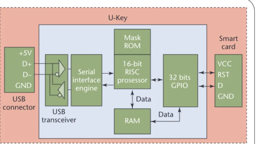
ure 2 illustrates the Key’s hardware components. U-Keys are common, but we designed this one ourselves.
U-Key hardware has five components1—a USB
con-nector, a USB transceiver, a serial interface engineer (SIE), a microcontroller unit (MCU), and a standard smart card—that both provide authentication and pro-tect important data.
U-Key software
In our approach, we used a U-Key as a token for secure authentication and storage. Accordingly, we categorize the related software into two parts depending on func-tion—authentication and secure boot functions appear in the boot phase, and the application’s trusted function call resides in the operating system’s user mode (see Figure 3). The application’s trusted function call interface gives applications in the user mode access to the U-Key’s func-tions. If the user application needs an integrity check on its configuration files, for example, it can use this inter-face to achieve that goal. The application’s trusted func-tion call interface is composed of three parts: the setup and maintain module, the manage module, and the func-tion call interface. To provide computer boot integrity and enforce access control, the U-Key must be initialized and loaded with configuration information for each of these parts.
The setup and maintain module initializes the U-Key and provides cryptographic hashes to the file system’s storage. Although the smart card file system is defined in ISO7816-4 (www.cardwerk.com/smartcards/smart-card_standard_ISO7816.aspx), it’s officially specified as a low-level hierarchy-based file system that’s organized into a collection of three elementary file types—master file (MF), dedicated file (DF), and elementary file (EF). The manage module sets the U-Key’s access control in-formation, such as who can read information from the U-Key’s memory.
Grub’s authentication and secure boot modules pro-vide the authentication and secure boot functions. After configuration, the user can employ the U-Key at boot time, before the operating system is loaded (when only the BIOS is running). A real-mode U-Key driver gives access to the U-Key at boot time.
Real-mode U-Key driver
From our earlier description, we know that to access the U-Key in Stage 1.5, we should communicate with the U-Key through a USB port before the operating system is loaded. This means we need a real-mode U-Key driver. At the time of our research, such a driver didn’t exist, so we created one.
Applications rely on the operating system’s USB dri-ver (USBD) to access the USB device; the USBD layer relies on a common interface to the hardware, which is called the host controller interface (HCI). Before the op-erating system is loaded we can’t access the USBD, so to access the USB device during the booting phase, we need to get to the HCI directly. To date, two interfaces are
de-Figure 2. U-Key architecture. Its main functional part is the smart card.
USB connector U-Key Serial interface engine 32 bits GPIO VCC RST D GND +5V D+ D– GND 16-bit RISC prosessor RAM Data Data Mask ROM USB transceiver Smart card
Figure 3. U-Key’s software layers. It’s composed of three layers—the driver layer, the function layer, and the user interface layer.
Setup and maintain module Secure boot module in Grub
U-key function interface
Functions
Authentication Secure boot U-Key application trusted function call
Function layer Function call interface Manage module Authentication module in Grub U-Key driver USB Protocol stack
OS kernel BIOS function call interface Real-mode U-Key driver
User interface Driver layer Software at host side U-Key hardware Smart card USB host controller
fined between the host and the HCI layer: Intel’s Univer-sal HCI (UHCI) Specification2 and the Open HCI Specification.3We used the UHCI because most moth-erboards use Intel chips.
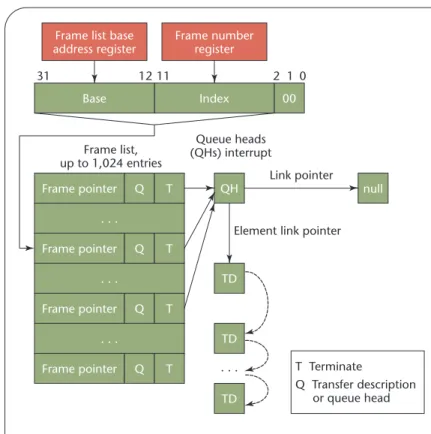
The UHCI consists of two parts, the host controller driver (HCD) and the host controller (HC). The HCD interprets requests from the USBD and builds data struc-tures such as the frame list, transfer descriptor (TD), queue head (QH), and data buffer for the HC. The HCD builds these data structures in system memory, and they contain all the necessary information to provide end-to-end communication between client software in the host and peripheral devices on the USB. The HC resides as function number two inside the peripheral component interconnect (PCI) South Bridge chip.4This location turns the USB controller into a member of the PCI-to-ISA Bridge family of devices, together with the proper ISA Bridge and the Integrated Drive Electronics (IDE) controller inside the Intel PIIX4 device. Figure 4 shows the relationship between the PCI South Bridge chip and the U-Key. The HC is accessible through the PCI con-figuration space; the real-mode U-Key driver’s task is to drive the U-Key through the HC in the PCI Bridge chip. Figure 5 shows how a frame list (of up to 1,024 entries) handles scheduling with the UHCI. Each entry is a pointer to the first structure to process in a given frame. The 4-Kbyte frame list table is aligned on a 4-4-Kbyte boundary. The HC accesses the frame list from the frame list base ad-dress register and the frame number. The register provides the location of the frame list table in system memory, and the frame number provides the index into the list.
The HC moves data between system memory and de-vices on the USB by executing the HCD-generated schedule lists; the HC also reports the status of transactions on the USB to the HCD. The HC walks the schedule list one entry at a time as it generates the next 1-ms frame.
With the U-Key, “control and interrupt” transfers shift commands and data between host and device. First, the HCD creates the transfer descriptions (TDs), which express the characteristics of the host-requested USB transaction. Then the HCD creates queue heads (QHs), which support the “control and interrupt” transfers’ basic requirements. After this step, the HCD links the TDs to the QH, and the QH to the frame list. When these steps complete, the “run” bit in the command register sched-ules the data transfers. The HC fetches the TDs and gen-erates the proper transaction on the USB. When it finishes, the transaction’s status is stored in the TDs.
U-Key configuration
The U-Key’s configuration entails loading the crypto-graphic hashes for Grub Stage 2 and the operating system kernel onto the U-Key itself. File integrity information is also loaded into the U-Key at this time (for the integrity check after the operating system has run). To perform
au-thentication at boot time, the administrator can also load the key for internal authentication (KI), the key for
exter-nal authentication (KE), and the user PIN.
Figure 4. The relationship between the peripheral component interconnect (PCI) South Bridge chip and the U-Key. The U-Key is driven through the USB host controller (HC) via the PCI South Bridge chip.
U-Key Bridge/USBPCI South controller
USB bus IDE bus
PCI bus
ISA bus
Hard disk device
Figure 5. Data transfer schedule. To make the host controller (HC) control the U-Key, we need a data transfer schedule between the HC and the U-Key.
Index 00 Frame pointer . . . Q T 0 2 1 11 31 Frame list, up to 1,024 entries Queue heads (QHs) interrupt T Terminate Q Transfer description or queue head 12
Frame list base address register Frame number register Base Frame pointer . . . Q T Frame pointer . . . Q T Frame pointer Q T null QH TD TD TD . . . Link pointer
Our modified Grub
Once our U-Key was functional, the next step was to integrate it into the boot process. Naturally, the first step in this chain is the BIOS; the next step is to modify the boot loader.
In our current prototype, we used Grub instead of the Linux loader (LILO) as the boot loader for two reasons: • Our operating system, Kylin, is based on a microkernel
that needs a boot loader that can support the multiboot standard. LILO doesn’t, but Grub can boot myriad op-erating systems, including DOS, Windows, FreeBSD, and Linux.
• The Grub boot loader has a more flexible architecture. When LILO boots a Linux kernel, for example, it reads it directly from the disk by using a map file that holds previ-ously stored kernel location information. When we move the kernel or the disk geometry changes, we have to run LILO to generate a new map file. Grub was designed to overcome this problem: because it understands partitions and file systems, it can load a kernel that it wasn’t told about previously. No map file is necessary, and Grub doesn’t need to be re-run after installing a new kernel.
For more information about Grub’s specifications, see www.gnu.org/software/grub/.
Authentications added in Grub
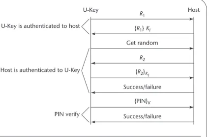
During system start up, the bootstrap process must per-form three authentications to complete the boot se-quence, as Figure 6 shows:
• First, the U-Key authenticates to the host. To do this, the U-Key must make available a secret shared with the
host (in this case, the KI). The ISO7816 standards for
smart cards provide basic functionality for authentica-tion, so the ISO7816 internal authenticate command returns a keyed hash of a short message (the challenge) to authenticate the card to the outside world.
• Next, the host is authenticated to the U-Key. To do this, the host must make available a secret shared with the U-Key (in this case, the KE). The external authenticate
com-mand conditionally updates the security status by using the card’s computation result (yes or no) based on a chal-lenge the card previously issued (such as a get chalchal-lenge command). Mutual authentication is reached in this step. • Finally, the user is authenticated to the U-Key via a PIN. The “verify” command compares the card with the verification data sent from the HCD, with the ref-erence data stored in the card. Only after PIN authen-tication success can the user communicate with the rest of the Key application. As a security feature, the U-Key administrator can set a maximum number of PIN retries. Once the count reaches zero, the U-Key will permanently block access to the card’s contents.
Once both the user and the mutual authentication be-tween the U-Key and the host are successful, the U-Key lets the PC read information from the U-Key’s memory and the boot sequence continues; otherwise, the boot process stops.
Integrity check function
Because the boot sequence precedes the application pro-gram’s execution—and even that of the operating system itself—antiviral software is ineffective at preventing boot-sector viruses. Thus for software defenses to be effective, we need a “clean boot.”
Figure 1 shows the integrity check process. We modi-fied Grub’s Stage 1.5 slightly: prior to loading Stage 2 into the main memory, Stage 1.5 computes and verifies a cryp-tographic hash of Stage 2 against a stored value for it in the U-Key. If the value is valid, control is passed to Stage 2.
We then modified Stage 2 slightly: prior to loading the operating system kernel into the main memory, Stage 2 computes and verifies a cryptographic hash of the oper-ating system kernel against a stored value for it in the U-Key. If the value is valid, control is passed to the operating system kernel.
At this point, the U-Key now sees that this particular kernel was booted in a trusted fashion. Any integrity fail-ures identified in this process will cause the boot process stop, and if everything is fine, the system proceeds normally. At configuration time, the system executable’s cryp-tographic hash can also be loaded into the U-Key. After the operating system boots, the comparison of exe-cutable hashes with those stored on the U-Key provides a virus detection mechanism that’s difficult to defeat. This approach is consistent with a recent trend to validate file
Figure 6. Grub authentication. It’s composed of user private identification number (PIN) authentication and mutual authentication between the U-Key and the host.
U-Key is authenticated to host U-Key R1 Get random {R1} KI Success/failure Success/failure {R2}KE {PIN}K R2 Host PIN verify Host is authenticated to U-Key
integrity rather than scan for known virus signatures. Al-though our approach isn’t a virus checker, it’s possible to detect modified versions of those files whose hashes are stored on the U-Key. The user can quickly learn if an ex-ecutable is suspect before it runs.
A
s attacks that modify the operating system itself be-come more common, we’ll see a stronger demand for secure bootstrapping. Although our scheme isn’t a full TPM, it’s a good alternative for improving computer se-curity. Unfortunately, the U-Key approach’s main limita-tion is that the integrity of both the MBR and Stage 1.5 isn’t verified during the bootstrap process.As we’ve shown here, we can boot a PC from the USB, but the place where the MBR is stored is much more secure than the hard disk. Our approach’s limitation is that it requires two USB ports and two USB devices to achieve a trusted boot process. In fact, we can integrate these two devices into one, which can function both as a smartcard and as a USB disk. We’ve designed such a de-vice in the Windows environment, but how to make its real-mode driver is the next step of our work. We’ve done some research into this material, but so far, we have yet to implement it.
References
1. P. Shuanghe, T. Weimin, and M. Yali, “The Implemen-tation of T=0 Protocol for a Smartcard Based on a USB Control Chip,” J. Computer Applications, vol. 24, Oct. 2004, pp. 67–69.
2.Universal Host Controller Interface Design Guide, v. 1.1, Mar. 1996; www.intel.com/technology/usb/uhci11d.htm. 3.Open Host Controller Interface Specification for USB, v. 1.0a,
Sept. 1999; www.intel.com/technology/usb/ehcispec.htm. 4. Intel 82801DB I/O Controller Hub 4 (ICH4) data sheet, Intel, May 2002; www.intel.com/design/chipsets/ datashts/290744.htm.
Peng Shuangheis a lecturer in the Research Center of Infor-mation Security Architecture at Beijing Jiaotong University. Her research interests include information security and embedded systems. Shuanghe has a PhD in computer application tech-nology from the School of Computer and Information Technol-ogy at Beijing Jiaotong University. Contact her at shhpeng@ sohu.com.
Han Zhenis a professor in the Research Center of Information Security Architecture at Beijing Jiaotong University. His research interests include graphics and information security. Zhen has a PhD in application mathematics from the Institute of Comput-ing Technology in the Chinese Academy of Sciences. Contact him at [email protected].
IEEE Pervasive
Computing delivers the
latest peer-revieweddevelopments in pervasive, mobile, and ubiquitous
computing to developers, researchers, and educators who want to keep abreast of rapid technology change. With content that’s accessible and useful today, this publication acts as a catalyst for progress in this emerging field, bringing together the leading experts in such areas as