Air Force Institute of Technology Air Force Institute of Technology
AFIT Scholar
AFIT Scholar
Theses and Dissertations Student Graduate Works
12-2019
Evaluating the Resiliency of Industrial Internet of Things Process
Evaluating the Resiliency of Industrial Internet of Things Process
Control Using Protocol Agnostic Attacks
Control Using Protocol Agnostic Attacks
Hector L. RoldanFollow this and additional works at: https://scholar.afit.edu/etd
Part of the Industrial Technology Commons, and the Information Security Commons
Recommended Citation Recommended Citation
Roldan, Hector L., "Evaluating the Resiliency of Industrial Internet of Things Process Control Using Protocol Agnostic Attacks" (2019). Theses and Dissertations. 3152.
https://scholar.afit.edu/etd/3152
This Thesis is brought to you for free and open access by the Student Graduate Works at AFIT Scholar. It has been accepted for inclusion in Theses and Dissertations by an authorized administrator of AFIT Scholar. For more information, please contact [email protected].
EVALUATING THE RESILIENCY OF INDUSTRIAL INTERNET OF THINGS
PROCESS CONTROL USING PROTOCOL-AGNOSTIC ATTACKS
THESIS
Hector L. Roldan, Captain, USAF AFIT-ENG-MS-19-D-006
DEPARTMENT OF THE AIR FORCE AIR UNIVERSITY
AIR FORCE INSTITUTE OF TECHNOLOGY
Wright-Patterson Air Force Base, Ohio DISTRIBUTION STATEMENT A.
The views expressed in this thesis are those of the author and do not reflect the official policy or position of the United States Air Force, Department of Defense, or the United States Government. This material is declared a work of the U.S. Government and is not subject to copyright protection in the United States.
AFIT-ENG-MS-19-D-006
EVALUATING THE RESILIENCY OF INDUSTRIAL INTERNET OF THINGS
PROCESS CONTROL USING PROTOCOL-AGNOSTIC ATTACKS
THESIS
Presented to the Faculty
Department of Electrical and Computer Engineering Graduate School of Engineering and Management
Air Force Institute of Technology Air University
Air Education and Training Command In Partial Fulfillment of the Requirements for the Degree of Master of Science in Cyberspace Operations
Hector L. Roldan, BS Captain, USAF
December 2019
DISTRIBUTION STATEMENT A.
AFIT-ENG-MS-19-D-006
EVALUATING THE RESILIENCY OF INDUSTRIAL INTERNET OF THINGS
PROCESS CONTROL USING PROTOCOL-AGNOSTIC ATTACKS
THESIS
Hector L. Roldan, Capt, USAF, B.S.C.S, SEC+
Committee Membership:
Barry E. Mullins, Ph.D., P.E. Chair
Timothy H. Lacey, Ph.D., CISSP Member
Stephen J. Dunlap, M.S., CISSP Member
AFIT-ENG-MS-19-D-006
v
Abstract
Water treatment centers, dams, traffic control systems, critical manufacturing, powerplants are just some examples of the critical infrastructure which support this nation and many others [1]. A malfunctioning or stoppage of any one of these systems could result in hazardous conditions on its supporting populace leading to widespread damage, injury, and even death. The protection of such systems has been mandated by the Office of the President of the United States of America in Presidential Policy Directive Order 21, dated 12 February 2013 [1]. Due to its importance and Presidential mandate, researchers and defenders of America alike have placed enhanced resources and focus on the critical infrastructure of this nation. This is all aside from the already ongoing research aimed at improving the management and efficiency of different Industrial Control Systems (ICS). Industrial Internet of Things (IIoT) provides a way for increased data collection and boosts in efficiency. IIoT are devices with dedicated purpose, microprocessors, and Internet Protocol capabilities; one such example being smart sensors. The problem is IIoT changes the way an ICS network functions. Controllers within an ICS now rely on networked devices to control a process. The question then arises, how does IIoT change the cyber-attack surface?
In legacy ICS operational designs, the sensors and actuators were directly hardwired to controllers. IIoT elevates this physical layer of abstraction allowing for devices to communicate over networks instead. In addition to this, IIoT devices use different protocols to communicate which are similar in design. The similarity in design could lead to unifying vulnerabilities. The research here aims to discover vulnerabilities common to IIoT via their network accessibility and protocols. It is predicted that due to the aforementioned, an ICS with IIoT could be disrupted by attacking the network supporting the controller and sensor without needing specific details of what industrial protocol is used. To test this, three different industrial protocol-agnostic network attacks
AFIT-ENG-MS-19-D-006
vi
are executed against a custom testbed. Because of their protocol-agnostic behavior, the attacks on the ICS network could likely affect a larger range of protocols than just the ones tested here. The attacks are an Address Resolution Protocol (ARP) cache poison, a corrupted-replay attack, and an intelligent replay attack. In addition to the attacks, a solution is then tested to determine what can be done to reduce these vulnerabilities while still enabling the use of networked sensors. The solution tested is the physical separation of operational and informational devices.
Overall the three attacks were not all together significantly successful, with only four of the nine experiments having effective results. The ARP cache poison is the most successful of the three attacks, disrupting the control process of the testbed 28 out of 30 times over three different smart sensors. The attack severed the connection between the controller and sensor analogous to cutting the virtual wire between the two. The two replay attacks are less successful in causing noticeable disruption. The only successful replay attack is the intelligent replay attack when executed between the controller and the Allen-Bradley smart sensor; all ten executions consistently led to the draining of the testbed tank. Additionally, the separation of the non-essential engineering computer (used as the attack platform) from the operational devices nullified the attack’s effects and mitigated the results seen in the attack experiments.
The few successful attacks simply showed how the relationship between the controller and the sensor are now more easily exploited due to its accessibility from the network and the nature of the industrial protocols which are employed. In addition to the accessibility, the similar design in protocols could likely mean this vulnerability can affect more than the protocols exploited here.
AFIT-ENG-MS-19-D-006
vii
AFIT-ENG-MS-19-D-006
viii
Acknowledgments
Thank you to the members of my committee, Dr. Barry Mullins, Dr. Timothy Lacey, and Stephen Dunlap. Your support, patience, and advice made the work more rewarding. Thank you to Lt Col Jeremy Jordan, Capt Seth Martin, Capt Rocco LiBrandi, and Lt Kenneth James for their mathematical mentorship and advice. I also cannot thank my wife and two boys enough for their endless love and support through the many hours spent away and mental absence when present.
“…Be as wise as snakes, innocent as doves”
-Matthew 10:16-
ix
Table of Contents
Page Abstract ...v Dedication ... vii Acknowledgments... viiiList of Figures ... xii
List of Tables ... xiv
List of Acronyms ...xv
I. Introduction ...1
1.1 Overview and Background ...1
1.2 Problem Statement ...2
1.3 Approach ...2
1.4 Assumptions and Limitations ...3
1.5 Research Contributions ...4
1.6 Thesis Overview ...4
II. Background and Related Research ...5
2.1 Overview ...5
2.2 Background ...5
2.2.1 Industrial Control Systems and Their History ...7
2.2.2 Supervisory Control And Data Acquisition ...7
2.2.3 Distributed Control Systems ...8
2.2.4 Human Machine Interfaces ...9
2.2.5 Workstations and Servers (Data Historian) ...9
2.2.6 Programmable Logic Controllers and Ladder Logic ...10
2.2.7 Proportional – Integral – Derivative Loop ...14
2.2.8 Smart Sensors and Actuators ...15
2.2.9 Industrial Protocols ...16
2.2.10 IO-Link ...23
2.2.11 Internet of Things and Industrial Internet of Things ...23
2.2.12 Address Resolution Protocol...26
2.3 Related Research ...26
2.3.1 Cybersecurity in Industrial Control Systems ...26
2.3.2 Industrial Control System Security and Malware ...27
2.3.3 Attacking Networked Devices ...31
x
2.4 Chapter Summary ...32
III. Testbed Design and Configuration ...34
3.1 Chapter Overview ...34
3.2 The Testbed and Upgrades...34
3.3 The Control Loop and Network Design...39
3.4 Solution Testbed Network Design ...41
3.5 Chapter Summary ...42
IV. Methodology ...43
4.1 Overview ...43
4.2 Objective ...43
4.3 Assumptions ...43
4.4 System Under Test ...43
4.5 Experiment Factors ...44 4.5.1 Attack Factor ...46 4.5.2 Sensors Factor ...48 4.5.3 Network Factor ...49 4.6 Metric ...49 4.7 Parameters ...50 4.8 Procedure ...51 4.9 Statistical Analysis ...51
4.10 Approximate Permutation Test ...54
4.11 Chapter Summary ...57
V. Results and Analysis ...58
5.1 Chapter Overview ...58
5.2 Baseline Analysis ...60
5.2.1 Section Overview and Success Metric ...60
5.2.2 Baseline and Permutation Test...61
5.2.3 Section Summary ...64
5.3 ARP Cache Poison Outcomes ...65
5.3.1 Outcome 1: Connection Cut at Set Point ...65
5.3.2 Outcome 2: Overflow Outcome ...67
5.3.3 Outcome 3: Drainage Outcome ...68
5.3.4 Outcome 4: Change in Direction of Water Flow ...69
5.4 Intelligent Replay – Outcome 5 Sensor Data is Successfully Manipulated ...70
5.5 Corrupted Replay and Subnetted Outcome 6: Little to No effect is observed ...73
5.6 Chapter Summary ...75
VI. Conclusion ...76
xi
6.2 Problem Statement Summary ...76
6.3 Research Contributions ...77
6.4 Research Limitations and Future Research...77
6.5 Recommendations for Security ...78
6.6 Conclusion ...78
Appendix A – Attack Scripts ...79
xii
List of Figures
Figure Page
1. A Simplified ICS Network... 6
2. A typical SCADA Network Composition... 7
3. MicroLogix 1100 Programmable Logic Controller ... 11
4. A depiction of Ladder Logic Branches, Inputs, and Output Instructions ... 12
5. Example of Rockwell’s SL500 Instruction Set Ladder Logic with Nested Rungs ... 13
6. Ladder Logic with No Nested Rungs... 14
7. PID Loop Diagram. ... 15
8. Ethernet/IP over TCP Packet Example. ... 18
9. Ethernet/IP over UDP Packet Example. ... 18
10. ModbusTCP Packet Example ... 19
11. ModbusTCP Transaction IDs ... 20
12. Distributed Computing Environment Protocol Example ... 21
13. Profinet Packet Example ... 22
14. Ether-S-IO Packet Example ... 23
15. IIoT Google Trends... 27
16. SANS ICS Attack Difficulty Scale ... 32
17. The Lab-Volt 3531 Main Cart Components ... 35
18. Lab-Volt 3531’s Computing Cart ... 36
19. Master Communication Modules ... 37
20. Mounted Smart Sensors ... 38
xiii
22. Legacy Testbed Network Design and Control Loop ... 40
23. New Testbed Network Design and Control Loop... 41
24. Solution Testbed Network Set up ... 42
25. System Under Test Diagram ... 44
26. Experiment Timeline ... 53
27. Calculating Original Difference in Medians ... 56
28. Randomly Redistributing Data and Calculate New Difference in Median... 56
29. Testbed Baseline True Level with Allen-Bradley Sensor ... 63
30. Testbed Baseline True Level with Balluff Sensor ... 63
31. Testbed Baseline True Level with DPT ... 64
32. ACP Attack with Sensor at Set Point and Draining ... 66
33. ACP Attack with Sensor at Set Point and Filling ... 66
34. Failed ACP Attack with Allen-Bradley Sensor ... 67
35. Overpressure Outcome... 68
36. Drainage caused by disconnection ... 69
37. Change in Direction of Water Flow ... 70
38. Intelligent Replay Result... 72
39. Ethernet/IP packet dissection ... 73
40. No Effect Observed with ACP against DPT on the subnetted network. ... 74
xiv
List of Tables
Table Page
1. Industrial Protocol Similarities ... 24
2. Factors Used to Construct the Experiments. ... 45
3. List of Experiments and Their Respective Order. ... 45
4. Procedure for Experiments ... 52
5. Summary of Experiment Results ... 59
6. Successful ARP-Cache Poison Difference P-Values and Time to Success (in seconds) . 60 7. Intelligent Replay Difference in Median Significance Test ... 60
xv
List of Acronyms
ARP Address Resolution Protocol...26
DCS Distributed Control Systems ...8
DPT Differential Pressure Transmitter ...3
ENIP Ethernet/IP ...34
ESIO Ether-S-IO ...17
HMI Human Machine Interface ...6
HTTP Hypertext Transfer Protocol ...16
ICS Industrial Control System ...1
IED Intelligent Electronic Device ...8
IIoT Industrial Internet of Things ...1
IoT Internet of Things ...24
IP Internet Protocol...1
IT Information Technology ...1
LAN Local Area Network ...9
MAC Media Access Control ...46
MITM Man-in-the-middle ...47
NIST National Institute of Standards and Technology ...5
OT Operational Technology...16
PLC Programmable Logic Controller ...1
SCADA Supervisory Control and Data Acquisition ...5
SUT System Under Test ...43
1
EVALUATING THE RESILIENCY OF INDUSTRIAL INTERNET OF THINGS
PROCESS CONTROL USING PROTOCOL-AGNOSTIC ATTACKS
I. Introduction 1.1 Overview and Background
The world of Industrial Control Systems (ICS) is ever evolving to find more efficient ways to manage processes, maintain control, and collect data for analysis. Some of this efficiency is made possible by Industrial Internet of Things (IIoT) devices, but due to the recent inception of the term, there is no set definition nor explanation on how it applies to critical infrastructure. The point of the term is to categorize devices that are considered to be smart and have specific functions in the network to which they are connected. Devices such as Programmable Logic Controllers (PLC), smart sensors, and smart actuators are some examples of IIoT devices. IIoT devices are not general Information Technology (IT) devices such as servers, computers, and network devices (switches and routers). In addition, IIoT devices complete a set of tasks, process, and communicate autonomously often through an Internet Protocol (IP)-based network. IIoT devices such as smart sensors present a potential solution to more efficient management of critical resources. These smart devices have abilities such as data storage, remote programmability, self-diagnosis, multiple endpoint communication, and more. Much can be gained by integrating smarter devices into an ICS network, but this capability relies on Transport Control Protocol and Internet Protocol (TCP/IP) networks to achieve its full potential and therein lies the concern. Prior to this point in the time span of ICS, components critical to the control of a process were hardwired to a controller
2
such as a PLC. Now with IIoT it is possible to have networked sensors and actuators which communicate with controllers over TCP/IP networks. Networked devices such as sensors and actuators change the way an ICS depends on its network to control a process. Before this point, an ICS could function autonomously from the network; now, an ICS requires 100% uptime of the operational network and its components to ensure networked dependencies (smart sensors and actuators) remain unsevered. The research explores how the reliance of IIoT changes the cybersecurity landscape of an Industrial Control System. The following experiments seek to determine the potential weakness of a process dependent upon IIoT, specifically networked smart sensors.
1.2 Problem Statement
With the integration of ICS and IIoT becoming more of a reality, many have wondered what does this mean for the future of ICS? The research here aims to discover how the introduction of IIoT to an ICS system opens the door for sets of vulnerabilities which could be common to more than one ICS network. More specifically, the goal of this research is to discover if attacks between PLC and IIoT could be performed without knowledge of the supporting industrial protocols. It is hypothesized that due to the ease of access from the network, the ICS can be degraded/controlled by attacking the network between PLC and IIoT without knowledge of what industrial protocol is used between the two.
1.3 Approach
This research utilizes the LabVolt 3531 Pressure, Flow, Level, and Temperature Process Training System (hereafter referred to as the testbed) located within the Center for Cyberspace Research at the Air Force Institute of Technology. The testbed’s legacy sensors are upgraded with
3
four different network-based smart sensors and one differential pressure transmitter (DPT) sensor which is interfaced with an Allen-Bradley PLC utilizing an analog input/output module and an Ethernet/IP module. The DPT is effectively converted into a network-based sensor using standard legacy equipment, emulating how this could be done in the field with current equipment. The DPT has similar capabilities as the smart sensors in the sense that it can be communicated from multiple simultaneous nodes, all through a TCP/IP-based network.
Experiments are carried out against the testbed testing different combinations of PLC, smart sensors, and network configuration to identify which attacks work in what conditions and which network configurations are most resilient.
1.4 Assumptions and Limitations
One limitation of the research is the controller hardware on the testbed. Although three different sensor setups are tested, there is only one programmable logic controller available to manage the process, the Allen-Bradley ControlLogix 1756 PLC. The assumption, however, is that the network attacks performed can work on other controllers since the attacks are brand agnostic relative to the controller or sensor. In other words, the attacks focus on affecting the network through which the ICS is now reliant on for control, not necessarily the device. Another limitation is the testbed only had one industrial protocol to test the payloads against, namely Ethernet/IP. As is the case with the PLC limitation, the concept demonstrated in this research shows that dependence on IIoT, specifically networked-based smart devices, widens the attack surface of an ICS network without needing much knowledge of the industrial protocols.
4
1.5 Research Contributions
The attacks presented in this research contribute to the field of IIoT cybersecurity, which is in support of the Presidential mandate. The attacks provide data in support for current best practices and how they apply not only to legacy systems but to IIoT-reliant ICS networks. Additionally, in order to test some of the notions in this research, the testbed is upgraded to include newer IIoT technology for proof of concept. The testbed adds to the growing field of testbeds which either lack or are starting to include IIoT for cybersecurity research [2, 3, 4]. This testbed can be further used by ICS cybersecurity researchers at the Air Force Institute of Technology. The attacks performed in this research demonstrate the possibilities of affecting a critical process through attacks on the network protocols supporting the PLC and IIoT device which could affect more than one protocol.
1.6 Thesis Overview
Chapter 2 covers the necessary information to understand the background and relevant research pertinent to this thesis. Chapter 3 describes the testbed, upgrades to equipment, settings for the entire testbed, and diagrams for proposed solutions. Chapter 4 details the experiments to take place along with the proposed statistical analysis performed on the data collected. Chapter 5 presents the results of the experiments, the analyzed data, and interpretation of the analysis. Finally, Chapter 6 offers conclusions, recommendations, and future work.
5
II. Background and Related Research 2.1 Overview
This chapter provides necessary background information and creates a sound foundational knowledge vital for comprehending the research covering ICS, IIoT, smart devices, and cybersecurity. Industrial Control Systems are the heart of society, with the resources they manage acting as the blood giving life to a nation at large. To gain a basic understanding of these networks and what makes them function, Section 2.2 discusses the hardware, network layout, standard protocols, and software present in a typical Industrial Control System network as well as the everyday terms seen in the industry. Finally, Section 2.3 presents a background in IIoT and relevant research pertaining to malware within industrial control systems.
2.2 Background
2.2.1 Industrial Control Systems and Their History
Many use the term ICS and Supervisory Control And Data Acquisition (SCADA) interchangeably, which is an understandable but inaccurate misconception; SCADA is only a subset of ICS. The best starting point is to define what is an Industrial Control System. It is a collection (or some combination) of computing, mechanical, and sensing devices responsible for controlling the management of some process [5]. SCADA is a specific application of ICS where the management of critical infrastructure and the centralization of data collection over a dispersed geographical area are both vital, and the network layout distinctly shows this. Figure 1 is an example of an ICS as provided by the National Institute of Standards and Technology (NIST) [6].
6
Figure 1. A Simplified ICS Network [6].
Several systems shown are needed for the smooth control of a process. A Human Machine Interface (HMI) is often a small computing device which receives status on the process and has options for an operator to control the process should the situation deem necessary; more on HMIs is discussed in Section 2.2.4. A sensor is a mechanical device which detects specific changes in the environment or process and transmits that status to the controller. The controller can be many types of devices that receive input (i.e., sensors, or human interaction via HMI) and then either make a change to the controlled process via an actuator based on programmed logic or sends warnings to connected systems. Much of the current and past research focuses on a popular device called a Programmable Logic Controller (PLC). A PLC accepts inputs in many different forms and completes tasks based on the inputs and the ladder logic currently running on it.
Before the architecture that exists today, many ICS networks were inaccessible from the Internet and operated by legacy equipment, hardwired in complicated ways and often needed
7
manual intervention to control the process [7]. Today’s architecture, however, exists because of newer technology such as PLCs, giving ICSs the ability for more streamlined communication using cheaper devices and adding one of the most significant benefits, the ability of automation, making it easier to correct errors and change the process if certain preprogrammed conditions are met. Because of devices like PLCs and other smart devices such as smart sensors and smart actuators, the modern SCADA network is made possible.
2.2.2 Supervisory Control And Data Acquisition
In comparison to a typical ICS network, Figure 2 illustrates a common SCADA architecture. Similarities between ICS and SCADA can be seen, such as a communication medium, a process managed by a controller, an HMI, along with other additions such as the Data Historian.
Figure 2. A typical SCADA Network Composition [6].
A typical SCADA network is categorized into four sections. The first section is the corporate network (not pictured) which is sometimes connected to the rest of the SCADA network separated
8
by a firewall; however, current research shows this is not recommended since it only makes it easier to enter the critical infrastructure from the Internet [8, 9].
The Control Center is responsible for the centralization of information pulling and command dispersion; this is what makes the SCADA network what it is – a system which conducts supervisory control and data acquisition. At this level, many of the reporting, management, maintenance, and diagnostic tools exist for operators to use and with which to supervise the controlled process.
The third section is the communication medium between the Control Center and the field units. This section can take many different forms such as telephone landlines, microwave communication towers, satellite connections, or Wide or Local Area Networks.
The last section of a SCADA network is known as the field site, which is where the critical process exists. The field sites contain endpoint communication devices, sensing units, and the devices critical to the management of the process such as PLCs or various Intelligent Electronic Devices (IED) which are capable of autonomous management.
Together, these four sections comprise a SCADA network and are one way the management of critical resources which are dispersed over large geographic areas can be accomplished. Again, SCADA is only a subset to ICS and can be contrasted to another subset known as a Distributed Control System (DCS).
2.2.3 Distributed Control System
Where a SCADA network is more specific to geographically-dispersed resource management such as natural gas pipelines or electric power distribution, DCS are considered a similar concept but are generally confined to “four walls” as is the case with water/wastewater treatment plants
9
[7]. DCS operate much like SCADA in the sense that the equipment is similar: HMIs, PLCs, workstations, Local Area Networks (LANs), and supporting servers. With the exception of physical separation, DCS and SCADA are very much alike.
2.2.4 Human Machine Interfaces
One of the devices that allows an ICS operator to see the status of their process and interact with the system are Human Machine Interfaces. These come in several forms; the first version ran on embedded systems. Typically, programs were designed and loaded onto a computing device specifically built to be an interactive display of information and control which came to be known as HMIs. As technologies and protocols progressed, the HMI evolved to run as software on a typical Windows or Unix workstation. This evolution facilitated web-based solutions where interaction is made possible by a web server and accessed through browsers on operator workstations. The HMI implementation decision depends on the needs of an operator and the resources a company is willing to commit.
2.2.5 Workstations and Servers (Data Historian)
The next portion of a SCADA network critical to the supervisory aspect is workstations and servers. These computing devices typically run Windows or Linux. Workstations can have multiple SCADA programs running. For example, a workstation could be running desktop HMI solutions, network diagnostic tools, proprietary software for ICS management and design, and include tools for engineers to program PLCs and other smart devices on the network. The applications of these workstations vary widely depending on the age of the ICS and process they manage. Typically, the best practice with workstations is to limit access to the control section of an ICS to “read-only” rights [10].
10
Servers have multiple purposes one of which was briefly mentioned: a host to web-based diagnostics and tools for an operator. Another function hosted on servers most commonly seen in an ICS is called a Data Historian seen pictured in Figure 2. The main purpose of a historian is to gather and analyze the controlled process using statistical techniques [7]. Historians come in proprietary (e.g., Siemens, Allen-Bradley, General Electric) and third-party solutions such as software that B-Scada provides free of charge [11]. Historians store gathered information known as “tags” which can either be information automatically polled and stored or operator-generated inputs. Historians serve multiple purposes as they provide information for both analytical and maintenance purposes but also can be used by corporations for business purposes.
2.2.6 Programmable Logic Controllers and Ladder Logic
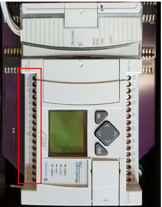
Automation is one reason why optimizations and resiliency of a managed resource are so easy. To achieve automation and optimization, a system needs the power of microprocessor-based devices, which can perform fast calculation and react to inputs faster than a human operator. One of the more popular devices is the Programmable Logic Controller such as the Allen-Bradley MicroLogix 1100 seen in Figure3. A PLC’s main function is to control a process as desired by the resource owner automatically. Using Figure 3 as an example, it has inputs labeled I/0-I/9 seen at the top of the PLC boxed in red. Using these inputs, the controller performs a series of checks in logic then triggers a series of outputs depending on the program.
11
Figure 3. MicroLogix 1100 Programmable Logic Controller.
If logic is programmed as intended, the process which the PLC manages is controlled accordingly. One language used to program the PLC is ladder logic; Figure 4 is a visual depiction of the basics (rungs, branches, input and output instruction symbols). In addition to this, two
12
examples are shown in Figure 5 and Figure 6; pictured is the SL500 Instruction Set which is supported by Rockwell Automation devices [12].
Figure 4. A depiction of Ladder Logic Branches, Inputs, and Output Instructions [13].
Ladder logic is a set of instruction rungs on a “ladder” which are assessed one rung at a time, top to bottom, left to right. Each rung needs at least one input instruction and one output instruction, as seen on rungs 0000 – 0003 boxed in red in Figure 6; input instructions are the inverted brackets on the left of the rungs and the output instructions look like parenthesis on the right side of the rung. Instructions can be in sequence, seen in rung 0004 in Figure 6, or in parallel as in rung 0000 in Figure 5. This parallel rung is called a branch and functions like a logical OR; if either the top or bottom evaluate to true statements, then the signal is passed to the next instruction. Parallel rungs help organize the overall program giving an engineer the option to simplify what sets of input conditions should assert a specific output [13].
Aside from ladder logic, a PLC can be controlled by an operator should the need arise. One way this is accomplished is through the use of HMIs as previously described. PLCs, HMIs, and
13
workstations can all be networked together to allow an operator to change the process should a need arise such as an emergency or system maintenance.
14
Figure 6. Ladder Logic with No Nested Rungs [12].
2.2.7 Proportional–Integral–Derivative Loop
One way to control a process, used by the testbed described in Chapter 3, is a Proportional-Integral-Derivative (PID) Loop. P is the proportion of measurement of error. In other words, it is
the comparison of two data points: where the process is currently at and where it needs to be adjusted to. It is a one-to-one relationship including its sign (positive or negative) indicating in which direction the error is and its value. I relates to the integral over time; it is how corrections
15
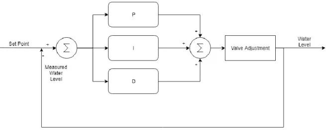
attempts to predict necessary future adjustments dependent on the current rate of change. Figure 7 is a visual depiction of the PID loop as a closed feedback loop of set point, the measure of water level, PID calculation, valve adjustment and feedback of new measure water level.
Figure 7. PID Loop Diagram.
2.2.8 Smart Sensors and Actuators
As previously seen in Figure 1, sensors and actuators are a significant portion of an ICS, acting very much like the human nervous system sensing and reacting to sound, light, pressure, and temperature. Without these, it would be impossible for an ICS to detect changes and act accordingly. If there is a need to detect a change in some state or current level of some process, then there exists a sensor to measure just that; it depends on what the ICS needs to manage. Some standard functions of ICS sensors measure changes in flow, temperature, single point pressure, differential pressure (pressure between two points), and more. Sensors send signals out to management devices with values corresponding to some measured state. Traditionally sensors and actuators performed only the function for which they were created: sense, report, and act. Now
16
with the recently engineered “smart” sensing/actuating technologies, this has changed. Now devices can self-diagnose, store relevant data, accept remote configurations, and communicate through TCP/IP networks which can include using wireless technology [14]. A critical component that gives these devices their smart capabilities is communicating with an enhanced protocol which supports the communication of diagnostics, data transfer, and configurations. IO-link is one example and is discussed in Section 2.2.10 [15]. In addition to the enhanced protocol, the smart sensors and actuators use a communication module which converts the device-specific protocol to an Ethernet-supported TCP/IP communication.
Although a benefit for the overall health of a process, since smart sensors gives an operator a real-time picture of the internal health of all their devices, this poses a question about the negative implications this could have relative to cybersecurity of the network.
2.2.9 Industrial Protocols
Each of the devices mentioned in Sections 2.2.4 - 2.2.6 and 2.2.8 use various protocols, and many times these protocols are proprietary and very specific to the type of device needing to be interfaced. In addition to their specific nature, most of the early protocols still in use were designed with little security in mind [7]. Typical protocols in an IT environment are Transmission Control Protocol (TCP), Internet Protocol (IP), and Hypertext Transfer Protocol (HTTP). In an Operational Technology (OT) platform, originally the need was low for these types of protocols since everything was hardwired with serial forms of communication due to the nature of the environment. Protocols such as RS-232 and RS-485 are physical-layer protocols much like Ethernet; however, their purposes are vastly different. RS-232 and RS-485 are standards that specify electrical, mechanical, and functional characteristics for serial binary communication circuits. Over time, attempts were made to standardize protocols, giving engineers options to
17
integrate devices and simplify the network, Modbus is one such example where it evolved to communicate over a TCP/IP network. This section focuses on protocols supporting IIoT devices. The examples discussed in this section are Ethernet/IP (ENIP), ModbusTCP, PROFINET/IO, and Ether-S-IO (ESIO). Each of the protocols mentioned use either TCP or UDP to communicate commands and information. These protocols share common characteristics such as device identifiers, connection status information, and sequence numbers.
Ethernet/IP utilizes both TCP and UDP for communication. ENIP uses TCP for management of devices and uses port 44818 at the destination end. ENIP communicates over port 2222 when UDP is used which is the method of choice for streaming IO data. An example of the protocol is highlighted in Figures Figure 8 and Figure 9 using the packet dissection tool Wireshark [16]. Some
of the common characteristics it shares with the next few protocols discussed are seen in the figures such as connection ID, sequence number, and the data portion where the IO information is held. The connection ID is used to keep track of conversations between nodes, this ensures all relevant data is interpreted together. The sequence number is so each node can know the successive order of the data received in the current connection; this way, if a node receives information that seems out of order, it can still differentiate what information is relevant to the current chronological timeline it is expecting.
Modbus is a serial-based protocol created by Schneider Electric (formerly Modicon) in 1979 [17]. ModubusTCP uses TCP, as indicated by the name, and port 502 [18]. It is a very popular protocol; there are currently over 670 companies that support the protocol including companies like Allen-Bradley, Siemens, Schneider Electric, and General Motors Inc. [17].
18
Figure 8. Ethernet/IP over TCP Packet Example.
Figure 9. Ethernet/IP over UDP Packet Example.
Shown in Figure 10 are the transaction identifiers (similar to ENIP). It links transactions (request and response) at the Modbus level so each node tracks which response belongs to which request [18]. The client’s transaction ID is copied and repeated in the response by the server to the client. This feature is needed especially in the cases where there are multiple MODBUS requests
19
over the same TCP connection such as the case would be if a bridge or gateway were being used. The transaction ID function as both a sequence number and connection ID if the connection is point to point; however if there is a gateway present then the unit identifier also functions as the connection ID. For all intents and purposes, the transaction identifier mainly functions as a sequence number, which behaves similar to the sequence number and connection IDs in ENIP as shown the network capture in Figure 11 incrementing predictably by one every transaction. Additionally shown in Figure 10 are the portions were Modbus transfers information/data along with an example of its command function.
20
Figure 11. ModbusTCP Transaction IDs [20].
Profinet IO is the next protocol operating under one additional protocol known as Distributed Computing Environment / Remote Procedure Call (DCE/RPC) which handles most of the control portions of Profinet that are similar to protocols seen before. Sequence numbers and meta-data information are handled at the DCE/RPC level as well as the Profinet level of the packet. Information such as device IDs and actual IO data (not pictured) is handled at the Profinet portion of the packet. Each of these is shown in the packet which is split up between Figure 12 and Figure 13 respectively.
The next protocol is Ether-S-IO, ESIO, created by Saia-Burgess Controls Ltd. It operates over UDP port 6060, and it is used to pass process IO between two nodes like how ENIP can be used to pass process IO. Figure 14 depicts the similar portions of the protocol headers it shares with the previous protocols mentioned. The main points of notice are the use of transaction IDs and source IDs along with its data portions.
21
22
23
Figure 14. Ether-S-IO Packet Example [22].
2.2.10 IO-Link
IO-Link is a new leading industry standard serial protocol for the enabling of direct input/output communication with smart sensors and actuators [15]. Many of the world’s leading industrial equipment manufacturers have accepted this protocol to support their smart devices such as Siemens and Allen-Bradley (Rockwell Automation). The protocol enables the many functions smart devices offer like communicating process data, device service data, triggered events as measured by the device, and remote device configuration.
In summary, the industrial protocols depicted here function in similar manners, each having the goal of transferring data from node to node, setting up communications, and sending/receiving commands as needed. The designs are visually displayed in Table 1. Connection or Transaction IDs are used to ensure the data received is relevant to the most current conversation. Sequence and
24
reference numbers are used to know the order in which the data received. It is a way for the receiver of the data to ensure the data is being received in the correct order it was sent. Additionally, each protocol has its methods of controlling and commanding devices.
Table 1. Industrial Protocol Similarities
2.2.11 Internet of Things and Industrial Internet of Things
A popular term which has exploded over the last decade is the Internet of Things (IoT). The term was first coined by Kevin Ashton in a talk he gave at Procter and Gamble in 1999 [23]. Ashton stated that he did not make the claim of ownership of the term but did provide what he originally intended with IoT. He stated computers received almost all of their information from people and this, in turn, was a limiting factor since people do not run continuously; we have “limited time, attention, and accuracy” [23]. Since this was the reality, the need to give computers the ability to gather information about the world around them was conceived. More specifically he stated “…If we had computers that knew everything there was to know about things—using data they gathered without any help from us—we would be able to track and count everything, and greatly reduce waste, loss, and cost. We would know when things needed replacing, repairing or recalling, and whether they were fresh or past their best [23].” To summarize, it seems his definition of the Internet of Things is an interconnection of objects (things) through the Internet
25
with the purpose of gathering and distributing information to track and reduce waste and cost, effectively increasing efficiency.
The term today has deviated from this intended definition slightly as seen by another definition found in a paper by Zanella and Vangelista: IoT are “…objects of everyday life [which are] equipped with microcontrollers, transceivers for digital communication, and suitable protocol stacks that will make them able to communicate with one another and with the users, becoming an integral part of the Internet [24].” There are many other variants of the definition but for this research, IoT is defined as the population of devices accessible through the Internet which are distinguished from traditional devices (server, computer, and router/switch) with the intent to communicate specific sets of information, perform specific tasks, and generally enhance quality of life.
There is much research in the area of IoT and its potential positive and negative impacts on society as the technology continues to advance and grow. Because manufacturing of IoT devices has become cheaper and easier over time, newer applications of IoT have been made possible; from thermostats and security devices, to augmented cattle, the ideas are still emerging [25] as well as being applied to areas of life such as the medical or industrial fields of which the latter is discussed next.
The industry has continued to evolve, looking for better ways to manage and distribute resources, and the next stage in that evolution has come. Industrial Internet of Things (IIoT) is another term that gained popularity most notably in the past four years based upon the Google Trends Tool which plots terms and their usage over time relative to when they reach their highest point; results of the tool for the term ‘IIoT’ are shown in Figure 15. The numbers are normalized to 100 and represent searches for the given region and time. The reason for IIoT’s rise in popularity
26
is difficult to determine, but a rise is present nevertheless. There are many deviations on the term IIoT, much like the case for IoT, so for the scope of this research a consolidated definition is given. If the perspective is taken from the ICS side and consideration is made that the root of the term is Internet of Things then Industrial Internet of Things are routable devices which aid in the monitoring and control of a critical process other than the standard IT type devices (routers, computers, servers) to include PLCs, embedded HMIs, Smart Sensors, and like devices.
2.2.12 Address Resolution Protocol
The networks that support the devices presented in Sections 2.2.1 - 2.2.10 use a standard protocol in this research known as Address Resolution Protocol (ARP). This protocol exists at Layer 2 (Link Layer) of the TCP/IP stack. Devices use this protocol to map physical addresses, known as Media Access Control addresses, to IP addresses. Devices keep track of all the addresses they detect in a cached table and use them when sending network traffic to a specific node.
2.3 Related Research
2.3.1 Cybersecurity in Industrial Control Systems
There are many case studies and real-world situations that show how important the topic of cybersecurity is in the realm of ICS. In December of 2017, Waterfall-Security created a top 20 list of real-world attacks and their vectors into ICS networks [27]. It is no surprise that Stuxnet and the Ukraine power grid attack made it on the list. The unfortunate truth is these are just the top 20 incidents, and there are likely many more which do not make it into the limelight. Some recurrent themes in the list are insider threats, ransomware, ranges of malware, and exploited trusted relationships.
27
Figure 15. IIoT Google Trends [26].
The many different avenues used to attack ICS networks are seen, but the most common theme is the fact these cases were enabled by Internet-connected avenues which is proof enough the dangers of making critical infrastructure publicly accessible. The Waterfall-Security report also presents a case where a poorly defended IIoT cloud service was compromised and used as a pivot into the ICS network. This is one example of the effect smart connected devices have on an ICS, and this research will explore other effects local to the ICS network in Chapter 5.
2.3.2 Industrial Control System Security and Malware
ICS and the domain of sub-variants suffer from dangerous security issues and weaknesses which are inherent to the need for support of legacy devices. This weakness is further fueled by
28
the financial undertaking needed to maintain and increase overall cyber security. This section presents several cases where these weaknesses have been exploited by malware both intentionally and unintentionally to varying levels of severity.
Starting with targeted attacks against ICS, the most popular is Stuxnet. It is one of the best examples of what intentional damage of an ICS looks like if an Advance Persistent Threat invests enough time and money into an attack. It used seven different exploits to propagate and achieve its apparent end goal which was to degrade the process at an Iranian uranium enrichment plant [28]. According to Symantec’s report, Stuxnet’s propagation into an air gapped facility likely started from a USB and spread from node to node via network exploits, removable media, and PLC project file infections [29]. Stuxnet was designed to penetrate deep into the operations portion of the ICS it targeted and required significant amount of intelligence, engineering, and resources to achieve. According to Symantec, Stuxnet was the first in malware history of its kind, using four zero-day exploits and stolen digital certificates to hide its presence. One aspect which displays the level of complexity is how far into an ICS structure it was able to penetrate; components of Stuxnet were tailored to the specific hardware in the ICS, namely the Siemens Step 7 family of PLCs [29]. As seen in Figure 2, this is the deepest level of an ICS aside from the actuators and sensors which support those PLCs. Thankfully, the level of complexity and skill required to build malware like Stuxnet is extremely high in today’s cyber landscape; however, it stands as a warning to the world of possibilities which can be achieved when the cyber world meets the physical.
Another example of a targeted ICS attack is Shamoon [30]. The malware was launched against the Saudi Arabian oil company Aramco in 2012. It destroyed around 30 thousand of the company’s computers by corrupting files and overwriting the Master Boot Record rendering the computers unusable. Although a targeted attack, it is important to note that the malware did not make it onto
29
the operational portion of the company’s network and yet it still caused considerable effects [28]. Like Stuxnet, the goal of the malware was to cause damage to a targeted ICS but dissimilar in sophistication and complexity. The malware was unable to make it over to the operational side of the company’s ICS but still caused a considerable amount of interruption to the company’s overall operations [31, 32].
In 2003, the Slammer Worm was one of the fastest spreading malware. It infected 75 thousand hosts, which included ICS networks, and reached its peak of possible targets within 10 minutes of launch. It spread using a buffer overflow targeting Microsoft’s SQL Server or Microsoft SQL Server Desktop Engine 2000 [33]. This worm is a case where malware was not specifically crafted to target ICS yet it still managed to infect and cause unwanted side effects. Moreover, the worm’s effects on the Internet and the infected host were side effects of replication rather than due to a payload. Slammer did not have a payload that executed and instead it was the Slammer worm’s network traffic from all its scanning which caused the denial-of-service in many systems worldwide. One of the more well-known affected hosts were two computers at the Davis-Besse nuclear plant. The plant’s infected computers which were affected dealt with monitoring the plant process and safety parameters [34]. If these two systems do not seem critical enough, the North East Blackout of 2003 was caused by an inability to stop conditions leading to a catastrophic blackout which were unknown to operators due to an error in software. The error prevented alarms from informing operators of conditions that could have been corrected and avoided if proper actions were taking in a timely manner. Since operators were unaware of the alarms, the conditions worsened and eventually led to cascading blackouts across North East America [35]. The blackout showed how a monitoring system’s failure could lead to potentially catastrophic situations.
30
Thankfully, in the case of the Davis-Besse facility, no further issues were reported due to the two temporarily disabled systems.
In the same year as the Slammer worm, another worm by the name of Blaster (aka Lovsan or MSBlast) spread across the world using an exploit which allowed it to affect Windows 2000 and Windows XP computers. The Blaster worm was similar to Slammer in its effects. The malware generated so much network traffic that it caused various denial-of-service attacks on a large number of computers. CSX Transportation Company is one such example of an ICS which was affected. The traffic overwhelmed CSX train signaling systems and halted all trains managed by the company, both commercial and transport, in the Washington D.C. area [36].
There are more recent examples which show worms still exist to this day. Some variants of ransomware function just like older worms, propagating using OS-based exploits which allow them to spread through a network from computer to computer with little to no user interaction. Two such examples of this are WannaCry and Petya both using the same exploits to replicate, spreading via a vulnerability in unpatched Windows systems using SMB version 1 [37, 38, 39]. WannaCry affected many different systems worldwide ranging from everyday users to companies such as Honda, causing them to halt operations [40]. Additionally, WannaCry affected some highly sensitive networks such as the National Health Service in England which led to many patients lacking timely care for their health needs [41]. According to Kaspersky Labs, Petya which functioned like WannaCry in exploits, seemed to specifically target industrial systems. Over half the hosts affected by Petya were oil, gas, manufacturing, healthcare, and finance [42]. Petya was reportedly to blame for affecting the systems that monitor the area around Chernobyl which is an area still suffering from the aftereffects of a nuclear meltdown that occurred in 1986 [43]. In addition to these systems, Chernobyl’s website which provided information to the public on
31
conditions and updates the power plant was brought down. As seen with the North East Blackout, safety monitoring systems are extremely important and could lead to significant issues if not dealt with in a timely manner.
In summary, these cases of malware show some key points. One, malware which affect ICS can be intentional or unintentional. And two, malware does not need to infect deep into an ICS network, such as controllers and sensors, to cause significant issues as was the case with Blaster worm and CSX. The outcomes previously stated show an unfortunate truth, if an ICS is in any way connected via a network, even if air gapped, it can suffer from operational interruption from malware which typically affects normal IT networks. This is due to commonalities such as similar operating systems and the operation somehow having an Internet connection somewhere in the network.
2.3.3 Attacking Networked Devices
Along the lines of testing the security of an ICS system, Blaine Jeffries, a graduate of the Air Force Institute of Technology, caused a networked Variable Frequency Drive to fault after flooding it with UDP traffic [44]. Jeffries’ research is an example that demonstrates how a controlled process which is reliant on networked devices, has a widened attack surface. The attack did not need knowledge of what protocol was used to succeed in faulting the Variable Frequency Drive.
2.3.4 The SANS Industrial Control System Cyber Kill Chain
Assante and Lee describe the process, ease, and sophistication of an attack on an ICS [45]. They state attacks which have the capability of impact on process or equipment need intimate knowledge of the process, the design of the ICS, and safety systems involved. This is
32
understandable since an attacker needs to understand more than just a typical network structure as well as specific industrial protocols. The authors used Figure 16 to depict the scale of difficulty of an ICS cyberattack visually. The scale goes from easy to extremely hard to achieve, outside of the circle to the inside respectively. To affect a process, for example, a denial-of-service attack, is considered somewhat easy to accomplish according to the scale. Furthermore, attacks which have a high chance of process or equipment effect is towards the harder end of the spectrum. The difficulty stems from how the authors define a difficult attack. If it has a high guarantee of success and repeatability, it likely took a significant amount of time in data gathering and testing.
Figure 16. SANS ICS Attack Difficulty Scale [45].
2.4 Chapter Summary
This chapter gives a brief overview of a typical ICS and two of its commonly known subsets, Supervisory Control and Data Acquisition and Distributed Control Systems, as well as the differences and similarities between each. A very brief description is given of equipment found in
33
each along with their intended purpose in an ICS. In addition, a discussion of the terms IoT and IIoT are given, which at a basic level are defined as devices with microprocessors, the ability to communicate across the Internet, and have dedicated purposes. The opportunities IIoT devices offer are vast, but because of how they can make a process reliant on the network instead of direct connection to control, this presents the concern and question of how does this change the attack surface of an ICS? In Chapter 4, attacks are crafted to explore the negative possibilities of malware which infect an ICS network reliant on devices like smart sensors.
34
III. Testbed Design and Configuration 3.1 Chapter Overview
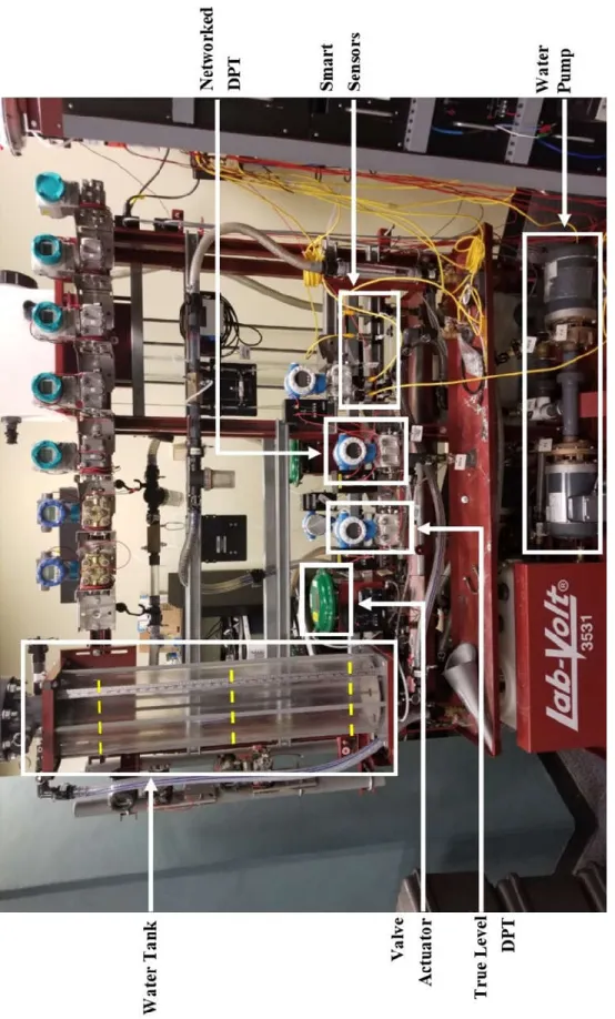
This chapter provides the details pertaining to the Lab-Volt 3531 Training System, otherwise known here as the testbed. The system is upgraded with the necessary equipment to make it a more connected system. The intent of the testbed is to train a student / engineer on a live and functioning system which can physically represent a micro-process of what is in practical use in many ICS. It has systems for pumping and draining water, regulating temperature, measuring flow rate, and other computing systems like a Human Machine Interface. The testbed is upgraded for this research with four smart sensors and a network-based DPT.
3.2 The Testbed and Upgrades
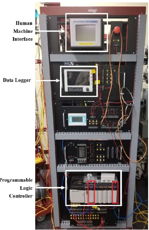
Figure 17 shows the central portion of the testbed which has a water tank, water pump, true-level DPT sensor, valve actuator, and new smart sensors. Additionally, pictured are dashed yellow lines on the water tank which indicate 100% full at 33 inches, 50% full at 18 inches, and 0% full at 3 inches. These values are chosen to allow for situations where the attacks could lead to extreme ends of the water level. Figure 18 displays the second cart which holds the computing components of the testbed. The components necessary to the experiments are the HMI, data logger, and the PLC. The HMI is strictly used to configure the set point, choose the respective smart sensor for the experiment, and start the water pump. The data logger is never officially used but is mentioned since it is on the same network as the other devices and polling the PLC for data. The PLC pictured has two Ethernet/IP (ENIP) modules boxed in red; for the sake of identifying the two, the leftmost is ENIP module 1 and the rightmost is ENIP module 2.
35
36
37
Mounted on the left of the computing cart, but not visible in Figure 18, are the IO-Link master communication modules. The sensors connect to these modules for their network capabilities; this is pictured in Figure 19. The two used for the experiments are identified with a 1 and 3 inside a red outlined star. Star 1 is the Allen-Bradley 1732E-8IOLM12R 8-Channel IO-Link Master, and Star 3 is the Balluff BNI EIP-507-005-Z040 IO-link Master Module. Star 1 is attached to an Allen-Bradley smart sensor, and Star 3 is attached to a Balluff smart sensor. The other two modules pictured are the same models; Star 2 has an Allen-Bradley smart sensor, and Star 4 has a Balluff smart sensor. The modules are for future research and connected to the network but are not used by the PLC for control during testing.
Figure 19. Master Communication Modules. 1
2 3
38
Figure 20 shows the two models of smart sensors installed on the testbed. The two in the red dashed boxed on the left are the Allen-Bradley 836P-D1NMGA14PA-D4 Solid State Pressure Sensors. The two in the red dotted box on the right are the Balluff BSP B002-FV004-D06S1A-S4 Pressure Sensors. Both sets of sensors can be operated as simple analog pressure sensors or put in a digital operating mode and communicate using the IO-Link protocol. For the experiments, the sensors operate in the digital IO-Link mode.
Figure 20. Mounted Smart Sensors.
The networked DPT pictured in Figure 17 gets its network capability by connecting to the analog module in slot 1 of the Allen-Bradley 1756 ControlLogix PLC in Figure 21 and communicates with the main PLC on the bottom of Figure 18 via the Ethernet/IP module in slot 0. This design demonstrates how network-based devices can be used to manage a process with today’s technology. In fact, the PLC in Figure 21 could provide similar functionality as the smart sensors such as diagnostic information and remote programmability.
39
Figure 21. PLC with Ethernet/IP and Analog Modules.
3.3 Testbed Control Loop and Network Design
Figure 22 shows the network design before the smart sensor upgrades. It provides a visual representation of the process and how the devices interact with the controlled process. The water is pumped into the tank at a constant rate of 5 L/min. The pressure is read by the hardwired DPT which sends the reading to the PLC. The PLC calculates how much it needs to adjust the valve and sends the signal. The valve then opens or shuts by whatever increment it is told, and the water drains accordingly. The important note about this setup is that even though the PLC is connected to the engineering PC, HMI, and data logger via the network switch, the PLC does not need them to control the process. If the network should go down the sensor is hardwired along with the actuator, and the PLC can continue to control the process.
40
Figure 22. Legacy Testbed Network Design and Control Loop.
Figure 23 represents the newly upgraded testbed which replaces the DPT with smart sensors. The portion highlighted in red represent the segment of the testbed which will undergo the network attacks. The smart sensor node in the figure represents the three different networked sensors described in Section 3.2 depending on the experiment. Because the sensors now need to communicate through the network to the PLC, the PLC is now dependent on the network to receive its sensor data in order to decide on how to control the valve. This dependency widens the attack surface of the ICS network to attacks which do not necessarily need to be targeted, as the protocol-agnostic attacks in this research shows. The network set up shown in Figure 23 best allows for the evaluation of attack surface.
41
Figure 23. New Testbed Network Design and Control Loop.
3.4 Solution Testbed Network Design
To help mitigate the weaknesses in dependencies on network-based smart sensing, a solution network configuration is tested which separates devices non-critical to the control of the process from devices which are critical devices. This network set up is seen in Figure 24 with the red portion depicting the expected reach of the network attacks to be performed. The network configuration separates the engineering PC from the nodes considered to be critical to the actual control of the process. It is through this network separation the network attacks performed in this research can be mitigated. The configuration is made possible by ENIP module 2 in Figure 18. The critical devices are connected to ENIP module 1 and are completely separated, network-wise, from the engineering PC.
42
Figure 24. Solution Testbed Network Set up.
3.5 Chapter Summary
This chapter provides the details on the setup of the testbed. The setup includes its IO-link communication module and smart sensor upgrades, the addition of a networked DPT sensor, and the two different network layouts which are used in the experiments described in Chapter 4.
43
IV. Methodology 4.1 Overview
This chapter presents details pertaining to the experiments carried out against the testbed. The end goal of the experiments is to discover the effects of protocol-agnostic attacks on an ICS network which depends on IIoT technology, specifically smart sensors, to control a process. To determine this, a series of experiments are conducted against the communication lines between the PLC and the master link communication modules of the sensors with protocol-agnostic network attacks, the goal of which is to degrade the process. The smart sensors are accessible to the network via communication modules which they are connected to; therefore, to affect the process through the pressure readings the attacks must be done between the PLC and the communication modules.
4.2 Objective
The objective of this research is to discover changes in attack surface by attacking the network which supports the smart sensors and PLC in order to disrupt the control process.
4.3Experiment Assumptions
It is assumed the time between experimental runs, determined by the procedure in Section 4.8, is enough to allow the testbed to reset fully and not have effects which crossed into the next experimental run.
4.4 System Under Test
To better picture the experiment, the System Under Test (SUT) and Component Under Test (CUT) are shown in Figure 25 and further depicts the factors, parameters, and metrics. The data for the metrics is polled from the PLC using a standalone laptop connected to ENIP 2 module. The
44
second module is used during the solution experiments to separate the engineering PC from the operational network. The component under test is the network supporting the PLC and IIoT device.
Figure 25. System Under Test Diagram.
4.5 Experiment Factors
The research presented in this chapter is summarized in Table 2. The table shows all possible factors and levels used to create a full-factorial experiment consisting of the 18 experiments in Table 3. The experiments are separated into two categories: the same subnet and subnetted. Their intent is to discover which network layout, sensor implementation, and attack combinations lead to network disruptions due to a process controlled by IIoT as well as which combination best
45
prevents such attacks. Each of the same-subnet experiment is run 10 times, and the subnetted experiments are only run 5 times since the expected outcome is no negative results from the attacks. Sections 4.5.1 through 4.5.3 describe each factor and their levels in the experiments.
Table 2. Factors Used to Construct the Experiments.
46
4.5.1 Attack Factor
The attack factor consists of three levels. All three attack levels are engineered in such a way as to be industrial protocol-agnostic, requiring no knowledge of protocols beyond the TCP/UDP layer. The attacks take advantage of the unifying features previously depicted in Table 1 without needing to know the specific protocols in use. Since the attack levels are protocol-agnostic, any observed outcomes could have comparable effects with other industrial network protocols because of the similar designs described in Chapter 2. Should any one of the experiments be successful in disruption, this would demonstrate a new method of disturbance an ICS process from the network which was not previously possible with legacy sensor equipment. Each of the attacks were written using a Python package called Scapy (version 2.3.3). The full scripts for each of the attacks used are located in Appendix A.
4.5.1.1 Address Resolution Protocol Cache Poison
Since the PLC and sensors communicate over a network using standard IP protocols, this attack poisons the ARP tables of the sensor and PLC to confuse their media access control (MAC) address of the other node and renders them unable to pass the current pressure reading to each other. This attack focuses on the Transport Protocol column shown in Table 1. Two ARP packets are sent every five seconds, one to the PLC and one to the sensor. The expected result is traffic will no longer route correctly between the two nodes, severing the communication leading to some disruption of the process. This attack simulates what would happen if some denial-of-service attack would occur resulting in severing of network connection whether it be intentional or unintentional.
![Figure 1. A Simplified ICS Network [6].](https://thumb-us.123doks.com/thumbv2/123dok_us/350282.2538547/22.918.212.708.113.488/figure-a-simplified-ics-network.webp)
![Figure 2. A typical SCADA Network Composition [6].](https://thumb-us.123doks.com/thumbv2/123dok_us/350282.2538547/23.918.116.802.563.835/figure-typical-scada-network-composition.webp)
![Figure 4. A depiction of Ladder Logic Branches, Inputs, and Output Instructions [13].](https://thumb-us.123doks.com/thumbv2/123dok_us/350282.2538547/28.918.210.749.214.502/figure-depiction-ladder-logic-branches-inputs-output-instructions.webp)
![Figure 5. Example of Rockwell’s SL500 Instruction Set Ladder Logic with Nested Rungs [12]](https://thumb-us.123doks.com/thumbv2/123dok_us/350282.2538547/29.918.162.753.237.781/figure-example-rockwell-instruction-ladder-logic-nested-rungs.webp)
![Figure 15. IIoT Google Trends [26].](https://thumb-us.123doks.com/thumbv2/123dok_us/350282.2538547/43.918.207.717.104.571/figure-iiot-google-trends.webp)
![Figure 16. SANS ICS Attack Difficulty Scale [45].](https://thumb-us.123doks.com/thumbv2/123dok_us/350282.2538547/48.918.229.693.446.821/figure-sans-ics-attack-difficulty-scale.webp)