ISSN Print: 2327-4352
DOI: 10.4236/jamp.2018.611193 Nov. 22, 2018 2322 Journal of Applied Mathematics and Physics
Optical System Design of Telescope Based on
Mixed Modulation Diffractive Lens
Fei Li, Bo Lin, Xueying Jin, Mengyu Wang, Keyi Wang
Department of Precision Machinery and Precision Instrumentation, University of Science and Technology of China, Hefei, China
Abstract
Using of diffractive optical elements (DOE) in the Schupmann system offer a new way for the construction of ultra-large aperture telescope. The Fresnel Corrector, one of the DOEs, is the key device in the Schupmann system, which is used to correct the chromatic aberration introduced by the diffrac-tive primary lens called Magnifying Glass. Generally, in a large aperture tele-scope (>20 m), the Fresnel Corrector is a diffractive lens with a large aperture and a small f-number, which is difficult to process. In this article, an im-proved device with a small F number but a large rim feature size, called am-plitude and phase hybrid modulation Fresnel diffractive optical element (APHMFDOE), is used here as the Fresnel corrector. First, APHMFDOE with appropriate parameters is designed to match the dispersion of the Magnifying Glass so that the system meets the achromatic condition. Second, the optical characteristics of this improved system are simulated and compared with those of the general system based on the conventional Fresnel corrector. Our approach introduces a new dispersion correction device, which not only can eliminate the chromatic aberration caused by Magnifying Glass, but also can reduce the processing difficulty of Fresnel Corrector.
Keywords
Fresnel Corrector, Diffractive Telescope, Imaging System
1. Introduction
Using of diffractive optical elements (DOE) in the Schupmann system offer a new way for the construction of ultra-large aperture telescope [1] [2]. As a key chromatic aberration correction device, Fresnel Corrector, showed in the Schupmann system in Figure 1, is equivalent to a miniature version of
Magni-How to cite this paper: Li, F., Lin, B., Jin, X.Y., Wang, M.Y. and Wang, K.Y. (2018) Optical System Design of Telescope Based on Mixed Modulation Diffractive Lens. Journal of Applied Mathematics and Phys-ics, 6, 2322-2329.
https://doi.org/10.4236/jamp.2018.611193
DOI: 10.4236/jamp.2018.611193 2323 Journal of Applied Mathematics and Physics fying Glass in the system. Generally, in a large aperture telescope (>20 m), the diameter of the Fresnel Corrector is close to 1 m, while the F number of the Fresnel corrector is close to 1. As a Fresnel Corrector with a small F number and a large aperture is relatively difficult to process, it is necessary to improve it for easier processing. In our previous works, we have studied the theoretical design and simulation process of an amplitude and phase hybrid modulation Fresnel diffractive optical element (APHMFDOE), which is generated by adding a dif-fraction phase profile to the transparent band of the AFZP. The results showed that APHMFDOE can increase the feature size of the diffractive element without changing its F-number [3]. In theory APHMFDOE can reduce the processing difficulty of the Fresnel Corrector and increase the design freedom of it. In this paper, we consider using it as the Fresnel Corrector.
2. The Design Theory of APHMFDOE
The APHMFDOE is generated by adding a quadratic phase factor to the trans-parent band of the AFZP. According to the distribution law of the bands in AFZP, we know that the transmittance function of APHMFDOE has periodicity in the R-square coordinate system, and the period is equal to 2λ0 0f . Suppose the phase factor to be added is
(
2)
0
exp −ipkr 2f , p is an integer, the
transmit-tance function of APHMFDOE can be described as
( )
2
2 2 1
0 0
2 1 2 2
exp 2 2 0 k k k k r
i p k r r r
G r f
r r r
πα
λ +
+ +
− ≤ <
=
≤ <
(1)
where rk = k fλ0 0 , λ0 is the design wavelength, f0 is the focal length of the AFZP, and α is a value related to the chromatic dispersion. In order to facili-tate comparison with the phase of the spherical wave, we write the Fourier series expansion of A r
( )
in Equation (2).( )
(
)
(
)(
)
2
0 0
exp 2 exp 2 1.5
1 exp
2 2
m
G r i pk i k p m
p m mr
sinc i
f
πα π α
[image:2.595.211.539.498.702.2]α π λ +∞ =−∞ = − + − − × −
∑
(2)DOI: 10.4236/jamp.2018.611193 2324 Journal of Applied Mathematics and Physics Compared with the standard spherical wave phase factor, the focal length of APHMFDOE corresponding to the design wavelength λ0 can be described as
0 0
f′ = f m (3)
In addition, we can also obtain from Equation (2) that different diffraction orders have different efficiencies. The efficiency of the mth order diffracted light of APHMFDOE can be written as
2
1
4 2
m sinc p m
α
η = −
(4)
In order to more clearly study the variation of diffraction efficiency with dif-fraction order, we make the incident light wavelength equal to the design wave-length. Then we obtain that α is equal to 1. Substituting the value of α into
Equation (4) and simplifying it, one can obtain
(
)
2 21 0
4
0 2 , 0
1 2 1
2 1
m
m p
m p k m p
m p k
k η π − = = − = − ≠ − = + + (5)
It is easy to obtain that the diffraction efficiency of APHMFDOE is the same as the diffraction efficiency of the main diffraction order of AFZP when m = p + 1 [4]. According to Equation (3), the (p + 1)th diffraction order focal length of APHMFDOE corresponding to the design wavelength λ0 is equal to
(
)
0
0 1
f′ = f p+ (6)
It can be seen from Equation (6) that the focal length of APHMFDOE is less than the main focal length of AFZP if p is a positive integer. However, the fea-ture size of the diffractive element has not changed during the process of gene-rating APHMFDOE. That is to say, APHMFDOE can achieve a larger feature size than AFZP on the premise of the same focal length and diameter. We de-note the F-number corresponding to the light of the p + 1 diffraction order by F
and the feature size of APHMFDOE by ω. Using the relationship between the Fresnel zone radius and the focal length and wavelength, it is not difficult to ob-tain
(
)
0
2 p 1 F
ω= λ + (7)
Compared with the Fresnel zone plate and the phase Fresnel lens, the feature size of APHMFDOE is increased by p + 1 times. The increasing of the feature size of the Fresnel Corrector can improve the system design freedom.
3. Design and Simulation of Optical System
3.1. Design of Optical System
DOI: 10.4236/jamp.2018.611193 2325 Journal of Applied Mathematics and Physics people have proved this theory [5] [6].The most important condition in ensuring system achromaticity is
2
FC MG
f = −η f (8)
where fMG, fFC are the focal lengths of Magnifying Glass and Fresnel
Cor-rector, respectively, η is the magnification of the Reimager. So far, many dif-fraction devices, including Fresnel Zone Plate, phase Fresnel lens and photon sieves, have been used as Magnifying Glass [6] [7] [8]. Similarly, the main focal length of these devices are all inversely proportional to the wavelength showed in Equation (8).
0 MG0
MG f
f
λ
λ
=
(9) where fMG0 is the focal length of Magnifying Glass corresponding to the design wavelength λ0, and λ is the wavelength of the incident light. In addition, people often use phase Fresnel lens as the Fresnel Corrector in the existing re-search. As the focal length of the Fresnel Corrector also satisfies the Equation (9), it is easy to prove that their focal length at any wavelength satisfies Equation (8), if the design focal length of Magnifying Glass and Fresnel Corrector meets Equa-tion (8). Here we are going to use APHMFDOE as the Fresnel Corrector, so the most important thing is also that the focal length of APHMFDOE at any wave-length satisfies Equation (8).
From Equation (2), we can obtain the focal length of APHMFDOE corres-ponding to the wavelength λ, showed in Equation (10).
0 0f
f m
λ
λ
= (10) Substituting Equation (6) into Equation (10), one can obtain(
)
0 1 FC0 FC p f f m λ λ + = (11) where fFC0 and fFC are equal to f0′ and f , and are the focal lengths of Fresnel Corrector corresponding to the design wavelength λ0 and incident light wavelength. In general, it is easy to make the focal lengths corresponding to the design wavelength satisfy the achromatic condition by controlling the shape and structure of the Magnifying Glass and APHMFDOE, which is showed in Equation (12).
2
0 0
FC MG
f = −η f (12)
Simultaneous Equations (9), (11) and (12), one can obtain
(
)
2 1
FC p MG
f f
m
η +
= −
(13) It can be seen from Equation (13) that there is always a diffraction order m =
p + 1 that makes the system satisfy the achromatic condition. That is to say, APHMFDOE can be used as the Fresnel Corrector in theory.
DOI: 10.4236/jamp.2018.611193 2326 Journal of Applied Mathematics and Physics the expense of diffraction efficiency, and the diffraction efficiencies of different wavelengths of light are different. According to Equation (4), the diffraction effi-ciency of p + 1 diffractive order light of different wavelengths can be described as
2
1 14 2 1
p sinc p p
α
η + = − −
(14)
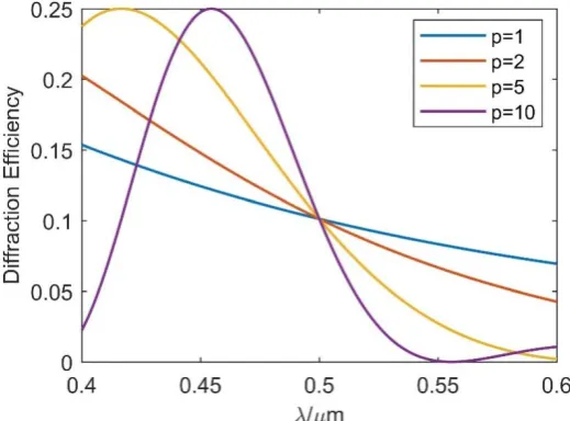
In order to understand the effect of APHMFDOE on the diffraction efficiency more clearly, we plot the diffraction efficiency as a function of the wavelength at different p values, which is showed in Figure 2.
It can be seen from Figure 2 that the relationship between diffraction effi-ciency and wavelength is very complex, and is quite different under different values of p. However, the diffraction efficiency decreases with the increase of wavelength, when the wavelength is near the design wavelength. Although the feature size of the Fresnel Corrector increases as the value of p increases, we cannot blindly increase the value of p. We must consider the effect of p value on the diffraction efficiency in the specific design.
3.2. Simulation Results of Optical System
In general, the F-number of the Fresnel Corrector should be greater than 1 or 2 due to the feature size. Based on this principle, Roderick A. Hyde gave two spe-cific design examples in his paper showed in Table 1 [1]. The design wavelength is 0.5 μm, while the spectral range is from 0.48 to 0.52 μm.
We replace the conventional Fresnel Corrector with an APHMFDOE, and list the design parameters of the new system here in Table 2.
[image:5.595.243.503.496.688.2]Comparing Table 1 and Table 2, we find that the Fresnel Corrector in the new system have a larger rim feature size under the same Eyepiece. In other words, it means that the new system can further reduce the length of the Eyepiece
DOI: 10.4236/jamp.2018.611193 2327 Journal of Applied Mathematics and Physics under the same rim feature size. Therefore, on the one hand, APHMFDOE can increase the feature size of the Fresnel Corrector and reduce the processing dif-ficulty of the Fresnel Corrector to some extent; On the other hand, it can reduce the length of the eyepiece and make the Eyepiece system more compact.
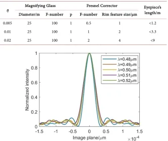
In order to better verify the reliability of APHMFDOE as a Fresnel Corrector, we simulate done of the new systems with η=0.01 showed in Table 2. Since there is no APHMFDOE surface type in the conventional optical design software, we wrote a program in Matlab to simulate the system, among which the physical propagation method was used. However, the simulation of the entire system re-quires a very large storage space and a very long running time due to the large aperture of the components of the system. So we only simulated the system in one direction, and then obtained the normalized intensity of the system at the image plane at different wavelengths showed in Figure 3.
[image:6.595.208.541.326.395.2]It can be seen from the simulation results in Figure 3 that the system has bet-ter focusing characbet-teristics for different wavelengths of light at the same image
Table 1. Roderick A. Hyde’s design examples.
η Magnifying Glass Fresnel Corrector Eyepiece’s length/m Diameter/m F-number F-number Rim feature size/μm
0.01 25 100 1 1 <9
[image:6.595.207.541.423.703.2]0.02 25 100 2 2 <3.3
Table 2. Design parameters of the new system.
η Magnifying Glass Fresnel Corrector Eyepiece’s length/m Diameter/m F-number p F-number Rim feature size/μm
0.005 25 100 1 0.5 1 <1.2
0.01 25 100 1 1 2 <3.3
0.02 25 100 1 2 4 <9
DOI: 10.4236/jamp.2018.611193 2328 Journal of Applied Mathematics and Physics
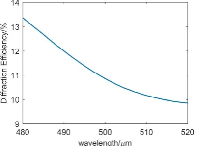
Figure 4. The diffraction efficiency of the scaled down system.
plane, and the focused spot size is basically the same. That is to say, the chro-matic aberration introduced by Magnifying Glass is well compensated by APHMFDOE. So we get a conclusion that APHMFDOE is feasible and reliable for use as a Fresnel Corrector. In addition, in order to explore the effect of APHMFDOE on the diffraction efficiency of the system, we need to know the intensity distribution of the whole image surface. Due to the large size of the telescope, the simulation of the entire optical plane requires a lot of sampling points, resulting in a large amount of computer-calculated data and a very long running time. So we simulated a scaled down system, which is equivalent to 10,000 times smaller than the original system. The diffraction efficiency of this system at different wavelengths was obtained and showed in Figure 4. The re-sults showed that the diffraction efficiency of the system decreases with the in-creasing of the wavelength, which is consistent with the theoretical effect of APHMFDOE on the diffraction efficiency of the system.
4. Conclusion
We have studied the theoretical design and simulation process of APHMFDOE as a Fresnel Corrector. The results show that APHMFDOE can be used as a Fresnel Corrector to compensate for the chromatic aberration introduced by Magnifying Glass. Its advantage is that it can increase the feature size of the Fresnel Corrector. However, these benefits do come at the expense of the dif-fraction efficiency of the system. The difdif-fraction efficiencies of the incident light of all the wavelengths are reduced, in addition, they are different at different wavelengths.
Conflicts of Interest
The authors declare no conflicts of interest regarding the publication of this pa-per.
References
DOI: 10.4236/jamp.2018.611193 2329 Journal of Applied Mathematics and Physics optics, 38, 4198-4212. https://doi.org/10.1364/AO.38.004198
[2] Hinglais, E. (2011) A Space Fresnel Imager Concept Assessment Study Led by CNES for Astrophysical Applications. Exp Astron, 30, 85.
https://doi.org/10.1007/s10686-011-9218-5
[3] Li, F., Cheng, J., Wang, M., Jin, X. and Wang, K. (2018) An Amplitude and Phase Hybrid Modulation Fresnel Diffractive Optical Element. Opt Commun, 413, 44-47.
https://doi.org/10.1016/j.optcom.2017.12.023
[4] Arsenault, H. (1968) Diffraction Theory of Fresnel Zone Plates. JOSA, 58, 1536-1536. https://doi.org/10.1364/JOSA.58.001536
[5] Koechlin, L., Rivet, J.-P., Deba, P., Serre, D., Raksasataya, T., Gili, R. and David, J. (2012) First High Dynamic Range and High Resolution Images of the Sky Obtained with a Diffractive Fresnel Array Telescope. Exp Astron, 33, 129-140.
https://doi.org/10.1007/s10686-011-9277-7
[6] Hyde, R.A., Dixit, S.N., Weisberg, A.H. and Rushford, M.C. (2002) Eyeglass: A Very Large Aperture Diffractive Space Telescope. Highly Innovative Space Telescope Concepts (International Society for Optics and Photonics 2002), 28-40.
https://doi.org/10.1117/12.460420
[7] Serre, D., Koechlin, L. and Deba, P. (2011) The Fresnel Imager: Learning from Ground-Based Generation I Prototype. Exp Astron, 30, 137-147.
https://doi.org/10.1007/s10686-010-9201-6
![Figure 1. Schupmann system used in a diffractive telescope [1].](https://thumb-us.123doks.com/thumbv2/123dok_us/9249977.413206/2.595.211.539.498.702/figure-schupmann-system-used-in-a-diffractive-telescope.webp)