A Control Mechanism of Stream Media Based on 3G
Network
Wei Jiang, Limin Meng, Songxiang Ying, Hong Peng, Zhijiang Xu
Zhejiang Provincial Key Laboratory of Communication Networks and Applications, College of information Engineering, Zhejiang University of Technology, Zhejiang, China.
Email: [email protected] Received 2012
ABSTRACT
In this paper, we use RTP/RTCP over unreliable UDP to realize the transportation of real time streaming. Meanwhile, according to the transmission feedback and network parameters, we analyze and calculate the network delay, packet loss and RTT (round trip time) to determine the network state. Finally, we propose a streaming media transmission con-trol scheme which could sense the network state and quickly adjust the rate of the sending side. It takes congestion, packet loss rate into comprehensive consideration and improves the overall performance of 3G network stream media.
Keywords: RTP; Delay; RTT; Control Mechanism; 3G
1. Introduction
With the development of wireless network, a variety of applications based on that come into live. A lot of re-search has already done on how to improve the perfor-mance of the high speed wireless network, including control mechanism. An Explicit Congestion Notification (ECN) [1] based on congestion control mechanism con-trols sending rate by marking the IP packets but can not control rate properly when a continuous packets loss happens. The end-system based source algorithm detects the nature and discriminate packet loss types to improve network performance by relative one-way trip time (ROTT) [2] or packet inter-arrival times [3].
As the development of the wired network is already quite mature, most of the current wireless applications are built in the IP packet network based on heterogene-ous wireless-wired hybrid network in which two main error types may affect the quality of stream media when we transfer media data [4,5]. They are congestion error in wired network and burst interference error in wireless channel. Most of the algorithms mentioned above can not deal with the burst interference error. Several approaches have been made to differentiate these two types of error [6-8].
In this paper, we distinguish the wired congestion as long time congestion from the wireless congestion as short time congestion. Our focus is to design a rate con-trol mechanism considering the packet loss rate and RTT which can adjust the sender behavior smoothly and when congestion happens we can detect, classify and control it,
thus we may get a higher utilization of the networks, im-prove the throughput and increase the packet successful delivery rate of the wireless networks.
2. Protocol and System Module
2.1. RTP/RTCP
RTP is an IP based application layer protocol which sup-ports real time audio and video data transmission. It en-capsulates the stream application data into RTP packet and then transfers through UDP. It meets the needs of high efficiency and real time character in real time stream media transmission since UDP is an unreliable and con-nectionless oriented protocol which does not contain re-transmission mechanism nor waiting for confirmation mechanism.
A Control Mechanism of Stream Media Based on 3G Network 9
adjust network state for the sake of media QOS (quality of service). The detailed information of RTP/RTCP is shown in RFC 3550[9].
2.2. System Module
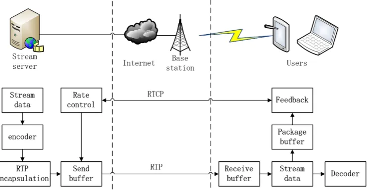
Stream media transmission system is the core of the whole system and its main job is to guarantee a high effi-ciency stream media transmission. To achieve that, there must be an interactive scheme between server and client which could provide a better QOS under all the circums-tances. Figure 1 shows the stream media transmission system module. Front end audio and video data are en-capsulated into RTP packet which would be stored and transmitted in the send buffer. This process is regulated through RTCP in order to prevent the network conges-tion. While the client receives the RTP packets, it puts them into receive buffer for restoring and analyzing. The restored data is sent to decoder for audio and video and the analyzed data is built into an RTCP packet to the sender for feedback.
2.3. Network Parameters
Black screen, mosaic, image pause, buffering phenomena often occur in the process of stream media services which strongly reduce the service QOS. Many factors contribute to these cases among which network conges-tion and packet loss are the main causes.
In order to improve the QOS of stream media, we take network parameters as real time transmission condition and dynamically changing basis. During the transmission, stream server gathers RTCP data periodically and calcu-lates the QOS parameters. Sender receives RR (Receiver Report) and analyzes the current state of the network, then promptly adjusts the rate of media by changing the
resolution and frame rate.
The packet loss rate is defined as the ratio of the num-ber of the missing data packet and sending data packet. Define the packet loss rate and the number of packets expected . Before the moment t, the receiver got the maximum and minimum sequence of RTP packet as
and , so here we have:
(1)
Suppose in reality the number we get the RTP packet is and the lost , then:
(2)
From the above, we get the packet loss rate:
(3)
RTT value calculation:
After the SR arriving, receiver sends an RR for feed-back. We define the delay between the SR and RR as DLSR (delay since last SR). We get LSR (last SR time-stamp) from the NTP of SR and put LSR and DLSR into the corresponding RR field. Suppose at moment A the receiver receives SR, then the one-way delay is (A-LSR). The receiver sends the RR at time B, then DLSR is B-A. Finally the sender receives the RR at time TB, then the RTT value can be calculated:
(4)
3. Stream Media Control Mechanism
[image:2.595.115.486.527.721.2]The streaming transmission control is mainly reflected in the media sending rate adjustment according to the net-work conditions. We mainly focus on reducing packet loss rate and the probability of congestion to achieve a higher quality of video.
3.1. Image Quality Determination
For long time congestion, packet loss is mainly due to network overload, so packet loss rate can be used as the basis of long time congestion. For short time congestion, large value of RTT is always expected, so we detect RTT value as the basis of short time congestion.
First, let’s take long time congestion into consideration. We define the network parameters’ threshold according to the image quality requirement. These values include packet loss rate and jitter etc according to which the network status can be classified into three categories. They are under-loading, full-loading and over-loading. Let M and N be the two threshold values for the three states. When packet loss rate is less than M, it indicates that the network is under-loading, so we can increase the sending rate to acquire a higher QOS. When packet loss rate is between M and N, it means the network is full-loading and we don’t have to change the sending rate. But when packet loss rate is more than N, we should slow down the sending rate to convert the over-loading network to a normal level. Figure 2 shows the relation-ship between network status and packet loss rate.
Packet loss rate directly affects the quality of picture which can be determined by PSNR (Peak Signal Noise Ratio) and MOS (Mean Opinion Score) [10]. PSNR is defined as follow:
( )
(
)
(
)
col row peak 2 0 0 col row PSNR 20 lg 1 , , , , N N S D i j n VY n i j Y n i j
N N = =
= −
∑ ∑
(5)The meaning of each part is shown in Table 1: MOS is widely used in audio and video quality mea-surement. This method uses arithmetic average to get the system running status of quantitative indicators of sub-jective evaluation. MOS can be divided into 5 grades as grade 5 means the picture is of best quality while grate 1 indicates the picture worst. Table 2 shows the corres-pondence between PSNR and MOS.
3.2. Determine the Threshold
Experiment uses multiple H.264 video streams which have been packaged into RTP packets and under multiple random packet loss condition to determine M and N. According to formula (3) and (5) we draw a relationship between packet loss rate and PSNR. Also, we take down the RTT value of each stream. The experiment is rec-orded in Table 3:
According to the table, we get Figure 3. From Figure 3 we can see, when PSNR is less than 20 dB, which
means packet loss rate is greater than 3%, MOS value is 2, that is to say, the picture quality is very poor. Gener-ally speaking, when PSNR is greater than 20 dB, the video quality is acceptable. On the basis of Figure 3, we select N 4% and M 2%.
Under-loading Full-loading Over-loading Packet loss rate
M N 100%
0%
Figure 2. Network status and packet loss rate.
Table 1. Meanings of symbol in PSNR.
Signal Meaning
n Picture sequence number
peak
V Vpeak=2k−1,k is the number of pixel per bit ( , , )
Y n i j Luminance value of a pixel
col
N The number of the horizontal pixels
row
N The number of the vertical pixels
Table 2. Relationship between PSNR and MOS.
PSNR MOS
>37 5(Excellent)
31-37 4(Good)
25-31 3(Fair)
20-25 2(Poor)
<20 1(Bad)
Table 3. Experiment record.
Number of video RTT value (ms) Packet loss rate PSNR (dB)
1 15 0.8 29.8
2 30 1.3 26.2
3 43 1.7 25.0
4 62 2.6 23.6
5 74 3.3 19.2
6 88 4.2 16.8
7 105 5.0 12.8
8 152 7.5 10.0
A Control Mechanism of Stream Media Based on 3G Network 11 0 5 10 15 20 25 30 35
0 2 4 6 8 10 12
P a c k e t l o s s r a t e / %
[image:4.595.59.285.85.231.2]PSNR/dB
Figure 3. Relationship between PSNR and packet loss rate.
Moreover, for the sake of network stability, a packet loss smoother is used to smooth the packet loss parame-ter. This is particularly effective when network faces the jitter problem as we shall observe a rather longer period of time to determine the packet loss and send rate. After the smooth procedure, the packet loss rate is:
( ) (
1) (
1)
( )
p n = −λ p n− +λp n (6)
where 0< <λ 1, the larger λ is, the more influence the new packet loss has. Here we set λ = 0.3.
4. Rate Control Mechanism
As we have already seen in Table 3, PSNR does not only have relationship with packet loss rate but also RTT val-ue. It is shown that if the current RTT value exceeds a normal too much, the quality sharply goes down, and it’s also not proper to have the same control algorithm with those whose RTT value is at a relative normal value. So when short time congestion occurs, we reduce the send rate to half of the current one. When long time conges-tion happens, we adjust the send rate by AIMD[41] scheme as the following formula.
( )
(
(
)
)
( )
( )
(
)
( )
1 0 2%
1 2% 4%
1 * 4%
R n p n
R n R n p n
R n p n
α
β
− + < ≤
= − < ≤
− >
(7)
where α and β are constants for rate adjustment, R (n) is the send rate at n moment, and 2% and 4% is the threshold value. The whole control mechanism flow chart is shown in Figure 4.
4.1. Experiment and Result
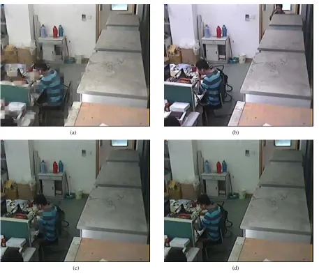
After we implement the control mechanism, the experi-ment result is shown in Figure 5. Video server can adjust to network congestion by regulating the send rate through RTCP. The overall QOS is improved. Figure 5(a) is a picture whose RTT value exceeds a normal value too much, which means the network encounters a short time
congestion. So we cut the send rate value to half of the former. Figure 5(b) shows the result. Figure 5(c) is a picture whose packet loss rate is 3.2% and PSNR value is 19 dB. It has mosaic effect and MOS grate reaches only 2. Figure 5(d) is a picture whose rate has been regulated and it has a packet loss rate of 1.5%, and its MOS reach-es 27. There is no mosaic on the picture and the total quality is acceptable.
Record the RTT value start
Is there a new RR arrive?
Is the current RTT within a normal
value?
Packet loss
Rate < 2 ? R'= R+
α
' 1 / 2 *
R
=
R
Packet loss
Rate > 4 ?
R
'
=
R
*
β
[image:4.595.314.528.191.585.2]Finish? end Yes Yes Yes Yes No No No No Yes No
Figure 4. Control mechanism flow chart.
5. Conclusion and Further Work
(a) (b)
[image:5.595.72.530.79.475.2]
(c) (d)
Figure 5. Experiment result.
There are several future works in this paper. Since we have already implemented the algorithm considering packet loss rate and RTT, some other parameters such as jitter and bandwith might be under consideration in the future.
6. Acknowledgements
This work was supported in part by Zhejiang Provincial Key Laboratory of Communication Networks and Ap-plications, College of information Engineering, Zhejiang University of Technology, Program for Zhejiang Leading Team of Science and Technology Innovation and Appli-cations and Zhejiang University of Technology.
REFERENCES
[1] H.J. Lee, H.J. Byun, J.T. Lim, "TCP-friendly congestion control for streaming real-time applications over wireless networks," IET Communications, 2008, vol. 2, no. I, pp. 159-163.
[2] N. Nguyen, E.H. Yang, "End-to-end loss discrimination for improved throughput performance in heterogeneous networks," In: 2006 3rd IEEE Consumer Commu-nications and Networking Conference (CCNC 2006), Las Vegas, NV, January 2006, pp. 538-542. [3] Y. Tobe, Y. Tamura, A. Molano, S. Ghosh, H. Tokuda,
"Achieving moderate fairness for UDP flows by path-status classification," In: 25th Annual IEEE Confe-rence on Computer Network (LCN 2000), Tampa, FL, November 2000, pp. 252-261
[4] Mengyue. Chen, “QoS algorithmic research based on wired-wireless hybrid network transmission,” master Thesis, Nanjing University of Posts and Telecommunica-tions, Nanjing, 2007.
[5] Yang. Xia, “WVTPx transmission rate control algorithm based on wired-wireless hybrid network” master Thesis, Nanjing University of Posts and Telecommunications, Nanjing, 2007.
A Control Mechanism of Stream Media Based on 3G Network 13
[7] D.Barman and I.Matta, “Effectiveness of loss labeling in improving TCP performance in wired/wireless net-work,”inProc.10th IEEE Intl. Conf. Network Protocols (ICNP),Paris,France,Nov.2002,pp.2–11
[8] J.Liu, I.Matta, and M.Crovella, “End-to-end inference of loss nature in a hybrid wired/wireless environment,” Pro-ceedings of WiOpt’03: Modeling and Optimization in Mobile, AdHoc and Wireless Networks, 2003, pp.78–82.
[9] Henning Schulzrinne, Stephen L. Casner, Ron Frederick and Van Jacobson, “RTP: A Transport Protocol for Real-Time Applications,” The Internet Society (IEFT), RFC3550, July 2003.