University of Warwick institutional repository: http://go.warwick.ac.uk/wrap
This paper is made available online in accordance with publisher policies. Please scroll down to view the document itself. Please refer to the repository record for this item and our policy information available from the repository home page for further information.
To see the final version of this paper please visit the publisher’s website. Access to the published version may require a subscription.
Author(s): Theodore L. Karavasilis, James M. Ricles, Richard Sause and Cheng Chen
Article Title: Experimental evaluation of the seismic performance of steel MRFs with compressed elastomer dampers using large-scale real-time hybrid simulation
Year of publication: 2011 Link to published article:
http://dx.doi.org/10.1016/j.engstruct.2011.01.032
Experimental evaluation of the seismic performance of steel MRFs with
compressed elastomer dampers using large-scale real-time hybrid
simulation
Theodore L. Karavasilis
1,*, James M. Ricles
2, Richard Sause
2, Cheng Chen
3 1Department of Engineering Science, University of Oxford, Oxford OX1-3PJ, U.K.2ATLSS Engineering Center, Department of Civil and Environmental Engineering, Lehigh University, Bethlehem,
PA 18015, U.S.A. 3
School of Engineering, San Francisco State University, CA 94132, U.S.A.
ABSTRACT
Real-time hybrid simulation combines experimental testing and numerical simulation, and thus is a viable experimental technique for evaluating the effectiveness of supplemental damping devices for seismic hazard mitigation. This paper presents an experimental program based on the use of the real-time hybrid simulation method to verify the performance-based seismic design of a two story, four-bay steel moment resisting frame (MRF) equipped with compressed elastomer dampers. The laboratory specimens, referred to as experimental substructures, are two individual compressed elastomer dampers with the remainder of the building modeled as an analytical substructure. The proposed experimental technique enables an ensemble of ground motions to be applied to the building, resulting in various levels of damage, without the need to repair the experimental substructures, since the damage will be within the analytical substructure. Statistical experimental response results incorporating the ground motion variability show that a steel MRF with compressed elastomer dampers can be designed to perform better than conventional steel special moment resisting frames (SMRFs), even when the MRF with dampers is significantly lighter in weight than the conventional MRF.
Key Words: Real-time hybrid simulation; damper; elastomer; steel MRF; performance-based seismic design.
1. Introduction
Passive damping systems can significantly enhance the seismic performance of buildings by reducing drift and inelastic deformation demands on the primary lateral load resisting system, in addition to reducing the velocity and acceleration demands on non-structural components [1]. Among the different kinds of passive damping systems, solid viscoelastic dampers have been extensively studied. These dampers generally consist of solid elastomeric pads bonded to steel plates. The elastomer pads exhibit both viscosity and elasticity and their mechanical properties depend on loading frequency, deformation amplitude and temperature.
*
Corresponding author: Tel.:+44 (0)1865 2 73144; fax: +44 (0)1865 2 73010
Many researchers have performed individual viscoelastic damper tests and developed models to predict damper behavior under earthquake loading. Tsai and Lee [2] and Kasai et al. [3] studied the effect of loading rate and temperature on viscoelastic materials and proposed fractional derivative models to predict damper behavior. Lee [4] studied the behavior of elastomeric dampers made of ultra high damping rubber and found from characterization tests that the behavior of these dampers to be less sensitive to frequency and ambient temperature compared to conventional viscoelastic dampers. Sause et al. [5] developed a sequential asymptote formulation to model the cyclic behavior of ultra high damping rubber dampers.
Other studies have developed seismic design procedures for buildings incorporating viscoelastic dampers and used nonlinear dynamic history analysis to evaluate seismic performance and damper designs. Fu and Kasai [6] presented a simplified theory to design viscoelastic dampers for a given MRF. Their simplified design method has been verified by performing nonlinear dynamic history analysis for a ten-story steel MRF with dampers. Lee et al. [7] presented a simplified design procedure for buildings with viscoelastic or high-damping elastomeric dampers. The design procedure has been used recently to study the effect of the variation in steel moment resisting frame (MRF) properties and damper design criteria on the design of steel MRFs with elastomeric dampers [8]. The 2000 NEHRP Provisions [9] include equivalent lateral force and modal analysis procedures for buildings with damping systems including viscoelastic dampers. The validity of the 2000 NEHRP procedures has been assessed by Ramirez et al. [10].
Several experimental studies have been performed on steel frames with viscoelastic dampers. These studies include mainly shaking table tests similar to those conducted by Chang and Lin [11] on a full-scale five-story frame, and recently by Kasai et al. [12] on a full-scale five-story steel building.
Recent research studies have proposed new kinds of viscoelastic dampers. Ibrahim et al. [13] proposed and analytically investigated a new visco-plastic device that consists of a block of a high damping rubber sandwiched between steel plates which are allowed to yield to provide additional energy dissipation. Karavasilis et al. [14] experimentally evaluated the hysteretic behavior of a new innovative compressed elastomer damper developed by Sweeney and Michael [15] and used the design procedure of Lee et al. [7] to design steel MRFs with compressed elastomer dampers. Nonlinear time history analyses confirmed the validity of the simplified design procedure and showed that steel MRFs with compressed elastomer dampers can be designed to perform better than conventional steel special moment resisting frames (SMRFs), even when the MRF with dampers is significantly lighter in weight than the conventional MRF.
dampers can be detrimental to the seismic fragility of acceleration sensitive nonstructural components.
To demonstrate the full potential of new types of dampers, damper designs and performance-based design procedures for structural systems with dampers need to be experimentally validated. The 2000 NEHRP provisions [9] allow the design of buildings with passive damping systems to experience controlled inelastic deformations associated with typical design drifts limits, e.g., the 2% drift limit [9]. Therefore, to experimentally validate damper designs and performance-based design procedures, inelastic response statistics incorporating ground motion variability should be obtained. Full-scale testing [12] is a reliable but, at the same time, a challenging experimental technique. In particular, conducting a series of full-scale tests to obtain response statistics of structural systems under earthquake intensities which produce inelastic deformations may be cost and time prohibitive since the damaged components of the structural system need to be repaired or rebuilt after each test.
Real-time hybrid simulation combines physical testing and numerical simulation such that the dynamic performance of the entire structural system can be considered during the simulation [19-21]. When real-time hybrid simulation is used to evaluate the performance of structures with rate-dependent damping devices, the damping devices can be treated as experimental substructures and the remainder of the structural system modeled analytically. The added benefit of this experimental technique is that it allows an unlimited number of ground motions to be applied to the structure, resulting in various levels of damage, without the need to repair the experimental substructures, since the damage will be within the analytical substructure. This paper presents an experimental program based on the use of real-time hybrid simulation to verify the performance-based seismic design of a two-story, four-bay steel MRF equipped with compressed elastomer dampers. The MRF was designed using a reduced base shear design force compared to a conventional SMRF, where the dampers are designed to control the drift of the structure. The laboratory specimens, referred to as experimental substructures, are two individual compressed elastomer dampers. The remainder of the building is modelled as an analytical substructure. A series of real-time hybrid simulations are performed to acquire response statistics under the design basis earthquake (DBE) and the maximum considered earthquake (MCE). The DBE has an intensity that is two-thirds that of the MCE, where the MCE has a 2% probability of exceedance in 50 years [9]. Real-time hybrid simulations are conducted using the Real-Time Integrated Control System [22] of the Lehigh Network for Earthquake Engineering Simulation (NEES) Real-time Multi-Directional Earthquake Simulation Facility (RTMD).
2. Compressed elastomer damper
The compressed elastomer structural dampers used in the study are fabricated by bonding four pieces of an elastomer (butyl rubber blend) onto a longitudinal steel bar, as shown in Fig. 1(a). The pieces of elastomer on this bar are then pre-compressed into a steel tube (Fig. 1(b)). Each prototype damper includes three tubes which are welded together (Fig. 1(c)). To enable the damper to be attached to the structure as shown in Fig. 1(d), transverse bars with bolt holes are welded across the steel tubes and additional transverse attachment bars are welded across the narrow dimension of the longitudinal bars (Fig. 1(c)).
and the steel tube is not mechanically bonded, which allows the elastomer to slip relative to the tube, producing friction when large deformations are imposed. The dampers are designed to slip before the elastomer tears or the bond to the longitudinal bar fails [15].
Characterization tests of the prototype damper were conducted by Karavasilis et al. [14] at the RTMD facility [22]. The loading protocol for the characterization tests used “ramped” sinusoidal displacement histories with different amplitudes and different frequencies. The experimental results showed that the dampers exhibit elastomeric behavior under small deformation (less than 15 mm) (Fig. 2(a)). When the deformation is larger than 15 mm, slip of the elastomer compressed inside the steel tube occurs and the dampers exhibit a combined elastomeric and frictional behavior (Fig. 2(b)). The damper assembly was tested with two prototype dampers (i.e., a total of 6 tubes) acting in parallel, referred to herein as a compressed elastomer damper.
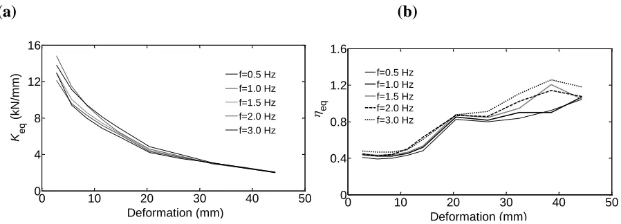
The equivalent stiffness, Keq, and the loss factor, ηeq, of the compressed elastomer damper
were determined from the characterization test data. The Keq is the ratio of the maximum force at
maximum displacement to the maximum displacement, while the equivalent loss factor, ηeq,
which represents the energy dissipation capacity, is defined as ηeq = ED/(2·π·ES), where ED is
the energy dissipated per cycle of sinusoidal loading and ES is the maximum strain energy stored during a cycle of sinusoidal loading. ED can be determined by integrating the hysteresis loops from the experimental data and ES can be calculated from the measured maximum stress and strain data. The Keq and ηeq from the characterization tests are given in Fig. 3. Fig. 3(a) shows
that the stiffness (Keq) decreases with increasing deformation, and slightly increases as the
frequency increases for a given deformation. The sensitivity of Keq to frequency diminishes as
the deformation increases. Fig. 3(b) shows that the energy dissipation (ηeq) is relatively constant
for small amplitudes of deformation (less than 10 mm) and significantly increases after slip of the elastomer occurs at about 15 mm. There is a slight increase in ηeq as the frequency increases
for a given deformation.
3. Steel MRF with compressed elastomer dampers
3.1 Prototype building
Fig. 4(a) shows the plan view of the 2-story, 6-bay by 6-bay prototype office building used for the study. The building is assumed to be located on a stiff soil site and has four identical perimeter steel MRFs to resist lateral forces. Each MRF consists of four bays. The design study focuses on one typical perimeter MRF. This MRF is designed either as a conventional SMRF as defined in the 2006 International Building Code [23], referred to herein as IBC 2006, or as a MRF with compressed elastomer dampers using the simplified design procedure (SDP) by Lee et al. [7]. In the latter case, dampers and diagonal braces are added to the two interior bays, as shown in Fig. 4(b).
The nominal yield stress of the steel members of the MRF is 345 MPa. The gravity loads and load combinations considered in the design are those described in IBC 2006. A smooth design response spectrum with parameters SDS=1.0g, SD1=0.6g, T0=0.12 sec and Ts=0.6 sec.
3.2 Design of perimeter MRF as a conventional SMRF without dampers
The perimeter MRF of Fig. 4(b) is initially designed as a conventional SMRF using the equivalent lateral force procedure from IBC 2006. This SMRF without dampers, referred to herein as UD100V, satisfies the member strength criteria and the drift limit of 2% of IBC 2006, where values of 8 and 5.5 are used for the response modification factor, R, and the amplification factor, Cd, respectively.
To study whether MRFs with compressed elastomer dampers can be designed to have a reduced strength compared to a conventional SMRF (without dampers) and achieve a prescribed level of seismic performance, the perimeter MRF was redesigned without dampers to have a design base shear equal to 0.50V, where V is the design base shear of UD100V. This MRF design is referred to as UD50V, and is significantly lighter than UD100V. A comparison of weight is discussed later. UD50V is subsequently outfitted with compressed elastomer dampers, where the SDP by Lee et al. [7] is used to design the dampers to limit the drift of the MRF to 1.65%. The SDP enables the design of the dampers to be integrated into the system design by specifying performance objectives that the combined MRF and damper system must achieve. Details of how the SDP is utilized are discussed later.
Table 1 summarizes the properties for the two MRF designs (UD100 and UD50V). The table lists the column section, beam sections, steel weight, fundamental period of vibration, T1,
and story stiffness (used later to design the dampers for the UD50V MRF). The last column of Table 1 provides estimates (based on the equal-displacement rule) of the expected maximum story drift, θmax, under the DBE earthquake. Under the assumption of the equal-displacement
rule, the UD100V frame was found to exceed the 2% story drift limit of IBC 2006, however, UD100V did satisfy the 2% story drift limit using the drift check procedure involving the use of
Cd per IBC 2006.
3.3 Design of dampers for SMRF
The SDP idealizes the damper hysteresis loops as linear viscoelastic ellipses and the damper design variables are the equivalent damper stiffness and the loss factor. The thickness and the area of the elastomer assumed in the prototype MRF and in the hybrid simulations presented in this paper are 4 times larger than the thickness and the area of the elastomer of the dampers tested by Karavasilis et al. [14]. Such an elastomer thickness ensures that the dampers in the prototype MRF will remain undamaged (i.e., no slip) under the DBE, while slip is expected under the MCE. Such a design strategy ensures no need to replace the dampers for seismic events lower than or equal to the DBE. For earthquakes larger than the DBE (e.g., MCE), the dampers are treated as sacrificial elements that should be replaced after the seismic event, if needed. The properties of the large-scale compressed elastomer damper design were derived from the experimental data presented in Fig. 3 as follows. With tref and Aref designated as
the thickness and area, respectively, of the elastomer damper used in the characterization tests, the properties (thickness t and area A) of the damper designs for the prototype MRF are expressed in terms of the ratios t/tref and A/Aref. Given the stiffness, Keq(uref), and the loss factor, ηeq(uref), of the damper in the characterization tests, the stiffness and loss factor of the damper
designs are: Kd(ud)(A/Aref)(tref/t)Keq(uref) and η(ud)=ηeq(uref), where ud is the deformation
imposed on the damper in the MRF, and uref is the deformation of the damper in the
force - deformation (Fref- uref) behavior to shear stress - shear strain (τ - γ) behavior using the tref
and Aref dimensions (i.e., τ=Fref/Aref and γ=uref/tref), and then by transforming the shear stress -
shear strain (τ - γ) behavior to force -deformation (Fd- ud) behavior of the damper designs using
the t and A dimensions (i.e., Fd= τA = Fref·A/Aref and ud= γt = uref·t/tref).
The SDP developed by Lee et al. [7] is slightly modified herein to account for the strong dependence of Kd(ud) and ηd(ud) of the compressed elastomer dampers on deformation amplitude ud. To achieve the target performance level (e.g., immediate occupancy under the DBE), detailed
design criteria, such as story drift limits and limits on the internal forces of the members need to be established. For the study herein, a value of θmax=1.65% under the DBE is specified as the
target performance objective. The modified SDP is then used, as explained below:
(1) Select an appropriate value (ratio of total brace stiffness per story in the global direction to the MRF story stiffness). This ratio should provide: (a) braces that are stiff enough so that the story drift produces damper deformation with minimal brace deformation; (b) braces do not buckle under the maximum forces transmitted by the dampers; and (c) only a small increase in the steel weight of the structure.
(2) Select an appropriate β value (ratio of total damper stiffness per story in the horizontal direction to the MRF story stiffness Ko). The β value should provide a reasonable required
number of dampers.
(3) Select an initial value of the damper loss factor, ηd. With the ηd selected, the contribution of
the dampers to the equivalent damping ratio of the MRF with the dampers, ξeq,is estimated based
on the lateral force energy method [26]. The damping reduction factor, B, is then obtained [9] as a function of the total damping ratio, ξt, which equals the sum of ξeq and the inherent damping
ratio of the MRF building (assumed to be 2%).
(4) Response spectrum analysis. The elastic response spectrum is reduced by the B factor, and the story drifts and damper deformation, ud, are calculated based on a response spectrum analysis
using the equal-displacement rule. In this analysis, dampers at each story are modeled with two linear springs (one spring at each interior bay) having horizontal stiffness equal to Ko·β/2. With ud known, the ηd(ud)= ηeq(uref) is calculated from Fig. 3(b) using uref ud(tref/t). Iterations of Steps 3 and 4 are performed until the value for ηd converges. If the story drifts after convergence
do not satisfy the established performance criteria, Steps 2 to 4 are repeated, beginning by selecting a new value for β.
(5) Calculate required number of dampers. With the ud known, the damper design stiffness Keq(uref) is determined from Fig. 3(a), and Kd(ud)(A/Aref)(tref/t)Keq(uref). The required
number of dampers, Nd, equals (Ko·β/Kd(ud)), rounded up to the nearest integer. If the number of
dampers is too large, a revised performance criteria and/or MRF design should be considered and Steps 1 to 5 are repeated.
Table 2 provides a summary of the damper design for the UD50V MRF where the performance criterion (as noted previously) is a design story drift of 1.65% under the DBE. It is observed that the MRF with 8 compressed elastomer dampers in the first story and 5 compressed elastomer dampers in the second story exhibits a significantly better performance (θmax = 1.65%)
than that of the conventional steel SMRF UD100V (θmax = 2.40%, see Table 1), where the design
prediction of θmax is based on the equal-displacement rule. Moreover, the UD50V MRF with
The damper imposes a limit on the peak damper force transmitted to the braces, the columns and foundation of the building by exhibiting a plastic (friction) behavior at higher drifts. This is a clear advantage over a conventional viscoelastic damper with uncontrolled peak damper force, since more economical designs can be achieved and braces able to safely support the dampers without buckling under high seismic intensity levels can be designed.
4. Real-time hybrid simulations
4.1 Real-Time Integrated Control System Architecture
The performance of a perimeter MRF with compressed elastomer dampers is experimentally evaluated by conducting real-time hybrid simulations. The ground motions only in the plane of the perimeter MRF were considered. The symmetry in the floor plan allowed only one perimeter MRF and the gravity frames and mass within the tributary area of the MRF to be considered. As illustrated in Fig. 5, the experimental substructures are two individual compressed elastomer dampers with the remaining part of the building (MRF, braces, and gravity frames (shown as a lean-on column in Fig. 5)) modeled as an analytical substructure. Since the dampers at a story level are placed in parallel in the prototype MRF (Fig. 4(b)), they are subjected to the same velocity and displacement. Therefore, each of the damper setups in the laboratory represents all of the dampers in one story. In a real-time hybrid simulation the measured restoring force from a compressed elastomer damper is multiplied by the number of dampers in a story to obtain the total restoring force of all the dampers at the story level in the MRF.
As discussed previously, the thickness and the area of the elastomer of the dampers that are used in UD50V MRF are considered to be 4 times larger than the thickness and the area of the elastomer of the dampers in the experimental substructure. Consequently, in the real-time hybrid simulation the command displacement of the dampers is scaled down by a factor of 4 and the measured restoring force is amplified by a factor of 4.
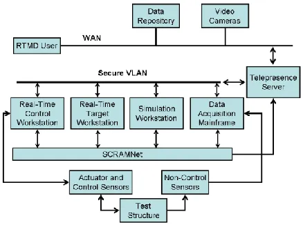
A nonlinear finite element program [27] has been implemented into the real-time integrated control system at the NEES RTMD Facility [22]. The architecture for the RTMD system is shown in Fig. 6. A digital servo controller (Real-time Control Workstation) with a 1024 Hz clock speed (sampling time t=1/1024 sec) controls the motion of the servo-hydraulic actuators and is integrated with the Real-time Target Workstation, Simulation Workstation, and Data Acquisition Mainframe using a shared common RAM network (SCRAMNet). SCRAMNet has a communication rate of about 180ns which enables the transfer of data among the integrated workstations in real-time with minimal communication delay. The nonlinear finite element program has been developed in a manner that enables the analytical substructure modeling, servo-hydraulic control law, and actuator compensation scheme (discussed later) to be integrated into a single SIMULINK model on the Simulation Workstation and then downloaded onto the Target Workstation using Mathworks xPC Target Software [28].
4.2 Analytical Substructure Modeling
(i.e., beams and columns) was modeled with three beam-column elements in series, i.e., two elements were used to model the two plastic hinge regions at each end of the member with a length equal to 5% of the member length and one element with a length equal to the remaining 90% of the member length. For the steel MRF under consideration, this modeling approach was found to produce inelastic response close to the response obtained with a rigorous analysis using fiber beam-column elements [27]. Diaphragm action was assumed at every floor in the MRF due to the presence of a composite floor slab. The lean-on column was used to model P-Δ effects on the MRF from gravity loads carried by the gravity columns of the building that were in the tributary area of the perimeter MRF. The inherent damping was modeled by constructing a Rayleigh damping matrix C (see Eq. (1)) based on a viscous damping ratio equal to 2% at the first and second modes of vibration.
4.3 Experimental Substructure Test Setup
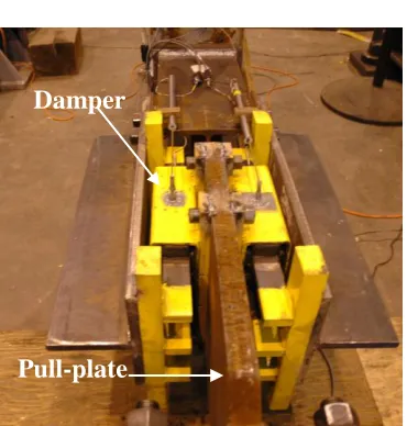
Fig. 7 shows the experimental setup for the real-time hybrid simulations, which consists of the experimental substructures (two compressed elastomer dampers) and two servo-hydraulic actuators with supports, roller bearings and reaction frames. The two actuators (see Fig. 5) have a load capacity of 2300 kN and 1700 kN with a maximum velocity of 840 mm/sec. and 1140 mm/sec, respectively, when three 1514 l/min three-stage servo-valves are mounted on each actuator. The 2300 kN and 1700 kN actuators were attached to the experimental substructures associated with the first story damper and second story damper, respectively. The servo-controller for the actuator used in real-time hybrid simulations consisted of a digital PID controller with a proportional gain of 20, integral time constant of 5.0 resulting in an integral gain of 4.0, differential gain of zero and a roll-off frequency of 39.8 Hz.
4.4 Real-Time Integration of the Equations of Motion
For the MRF with the dampers of Fig. 5, the temporal discretized equations of motion at the i+1th time step can be expressed as
1 1 1 1
1
i
e i a i i
i C x r r F
x
M (1)
where xi1and xi1 are the acceleration and velocity vectors of the structure, respectively; a i1
r and
e i1
r are the restoring force vectors of the analytical and experimental substructures, respectively;
M and C are the mass and damping matrices of the structure, respectively; and Fi+1 is the
excitation force.
The CR unconditionally stable explicit integration algorithm [19, 30] is used to solve Eq. (1) for the structural displacement vectorxi1. According to the CR algorithm, the variations of the displacement and velocity vectors of the structure over the integration time step t are defined as
i i
i x t α x
x 1 1 (2.a)
i i
i
i x t x t α x
x1 2 2 (2.b) where xi ,xi and xi are the displacement, velocity and acceleration vectors of the structure at the
ith time step, respectively; and 1 and 2 are matrices of integration parameters defined as
M C C K K
Mα
α 2 1
2
1 4 4 2 t ( eq) t ( eq) (3)
frequency ω and deformation amplitude ud, keq and ceq are equal to Kd(ud) and η(ud)∙keq/ω, respectively [1]. In the real-time hybrid simulations presented herein, ud and ω where assumed
equal to the expected damper deformation from the SDP and the first mode cyclic frequency of the building, respectively. Preliminary real-time hybrid simulations showed that the response results where insensitive to small variations of the selected values of ud and ω. Chen and Ricles
[32] showed that it is necessary to include the damping and stiffness of the complete structure in Eq. (3) to ensure that the integration parameters result in maintaining a stable solution. This will occur as long as the total stiffness (K + Keq) in Eq. (3) is larger that that developed in the system during the hybrid simulation.
In a real-time hybrid simulation, Eqs. (2.a) and (2.b) are used to obtain the velocity
1 i
x and displacement xi1 vectors at the i+1th time step. The displacement vector xi1 is decomposed into the analytical displacement vector a1
i
x and the experimental (or command)
displacement vector 1 ,
e i
x which are imposed onto the analytical and experimental substructures,
respectively, to obtain the restoring force vectors a i1
r and e i1
r . Strictly speaking, e1 i
x contains deformations, i.e., differences in the displacements of the nodes at the ends of the experimental substructures. The analytical restoring force vector a
i1
r is obtained with a standard nonlinear state-determination procedure for each beam-column element in the analytical substructure [29], while the experimental restoring force vector e
i1
r is obtained from the feedback forces measured using load cells that are placed in each compressed elastomer damper test setup. The equilibrium Eq. (1) is then employed to calculate the acceleration response vector xi1 at the i+1th time step,
and the velocity xi2 and displacement xi2 vectors for the next i+2th time step are then readily available from Eqs. (2.a) and (2.b). This process is repeated to obtain the response over the whole duration of the earthquake ground motion.
The integration time step Δt used for the hybrid tests is a multiple of the servo-hydraulic controller sampling time t of 1/1024 sec, and equal to 10/1024 sec. This size of the time step was arrived at by performing a convergence study to ensure that value for Δt was sufficiently small enough that the integration algorithm produced accurate results. A linear ramp generator is used to apply the command displacement vector xie1 through the hydraulic actuators to the
experimental substructures at the servo-controller sampling rate, i.e., at a time step t of 1/1024 sec. The interpolated command displacement vector is defined as
e i e i e i j c i n j x x x
d ( 1 )
) (
1 (4)
In Eq. (4), ( ) 1
j c i
d is the command displacement vector at the jth substep within the i+1th time step;
e i
x is the command displacement vector at the ith time step; and j is the substep index for the
interpolation within one single time step and ranges from 1 to n, where n is the integer ratio of
t/t (i.e., equal to 10 for the tests presented herein).
As noted above, to proceed to the next (i+2)th time step the restoring force vectors a i1
r and
e i1
r at the end of the (i+1)th time step must be obtained to calculate the displacement vector xi2 . The available time to perform the state determination of the analytical substructure and form the
a i1
r restoring force vector is equal to the integration time step Δt. For the analytical substructure of Fig. 5, a
i1
However, if the measured experimental restoring force vector e i1
r is fed back at the end of the
time step after the actuators reach their corresponding command displacementxie1, a delay occurs while xi2 is calculated and sent to the servo-controller, which reads the command
displacement xei2 one sampling time step t later. To avoid this delay and ensure a smooth and
continuous movement of the actuators, the experimental restoring force vector is extrapolated at the end of the (n-1)th substep within each time step (e.g., the (i+1)th time step) to become available before the actuators reach their command displacementxie1 [19], where for each
experimental substructure the restoring force contribution to e i1
r is:
) (
)
( 1 (1 1) 1 1( 1) ) 1 ( 1 1 n m i e i eq n c i e i eq n m i e
i r k x d c x x
r (5)
In Eq. (5) ( 1) 1 n m i
r is the measured restoring force of the experimental substructure for the (n-1)th substep of the (i+1)th time step, xie1 and xim1(n1) are the target relative velocity between the nodes at the ends of the experimental substructure based on the CR integration algorithm (Eq. (2.a)) and the measured velocity in the damper for the (n-1)th substep of the (i+1)th time step, respectively, and, as noted above, ceq and keq are the equivalent damping and equivalent stiffness of the elastomeric damper of the experimental substructure, respectively. The velocity of the experimental substructure is constant within the integration time step ∆t due to the linear ramp generator. Therefore, in the extrapolation procedure the last term in Eq. (5) is included to minimize the error in the velocity-dependent restoring force of the experimental substructure (elastomeric damper) at the end of the time step by correcting for the difference between the target velocity xie1 and the velocity produced by the linear ramp generator.
4.5 Actuator Delay Compensation
Due to inherent servo-hydraulic dynamics, the actuator has an inevitable time delay in response to the displacement command. This time delay is usually referred to as actuator delay and will result in a desynchronization between the measured restoring forces from the experimental substructure(s) and the integration algorithm in a real-time hybrid simulation. Studies on the effect of actuator delay [31, 32] show that actuator delay is equivalent to creating negative damping, which can destabilize a real-time hybrid simulation if not compensated properly.
To minimize the detrimental effect of actuator delay during the real-time hybrid simulations, the adaptive inverse compensation (AIC) method developed by Chen and Ricles [33] was used to compensate for actuator delay during the simulations. The AIC method for a servo-hydraulic can be expressed using the following discrete transfer function that relates the compensated command displacement to the original command displacement for the actuator:
z z z
G es es
c ) 1 ( ) ( )
( (6)
actuator control during a real-time hybrid simulation. The adaptation of the evolutionary variable
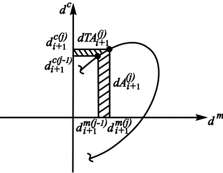
α is based on a tracking indicator TI [34]:
t kp TI t ki tTI d 0 ) ( ) ( ) (
(7)In Eq. (7) kp and ki are proportional and integrative adaptive gains of the adaptive control law, respectively. The TI is based on the enclosed area of the hysteresis in the synchronization subspace plot shown in Fig. 8, where the actuator command displacement dc is plotted against
the actuator measured displacement dm. The calculation of TI at each substep within a time step
is formulated as [34]
( )
1 ) ( 1 ) (1 0.5
j i j i j
i A TA
TI (8)
In Eq. (8), Ai(j1) and TAi(j1) are the accumulated enclosed and complementary enclosed areas at the jth substep of the ramp generator at time step i+1, respectively, and are calculated as
( 1)
1 ) ( 1 ) 1 ( 1 ) ( 1 ) 1 ( 1 ) ( 1 ) 1 ( 1 ) (
1 0.5
j m i j m i j c i j c i j i j i j i j
i A dA A d d d d
A (9a)
( 1)
1 ) ( 1 ) 1 ( 1 ) ( 1 ) 1 ( 1 ) ( 1 ) 1 ( 1 ) (
1 0.5
j c i j c i j m i j m i j i j i j i j
i TA dTA TA d d d d
TA (9b)
The incremental values for the enclosed and complementary enclosed areas, dAi(j1) and dTAi(j1), respectively, are shown in Fig. 8 for the jth substep of time step i+1. At the beginning of the test, the enclosed and complementary areas have initial values of zero. The calculation of A and TA
continues for every substep of each time step until the end of the real-time hybrid simulation.
Chen and Ricles [33] showed that the use of the AIC method for real-time hybrid simulation of structures with experimental substructures consisting of passive MR dampers resulted in good actuator tracking and test results in comparison with numerical simulation results for structural response.
For the real-time hybrid simulations a value of αes= 30 for the estimate of the actuator delay constant along with the values for the adaptive gains of kp=0.4 and ki=0.04 for both servo-hydraulic actuators were used. These values were established by Chen by conducting parametric studies of the servo-hydraulic systems at the RTMD [32].
5. Real-time hybrid simulation results
An ensemble of five earthquake ground motions recorded on stiff soil sites (without near-fault effects) are used in real-time hybrid simulation to evaluate the performance of the MRF with compressed elastomer dampers. The ground motions were scaled to the DBE level using the scaling procedure of Somerville [35]. The amplitudes of these DBE ground motions were further scaled by 1.5 to represent MCE ground motions. Table 3 provides the scale factors and information for the five ground motions, while Fig.9 shows their acceleration response spectra.
Time history results from real-time hybrid simulation are presented for the HSP090 record from the Loma Prieta 1989 earthquake scaled to the DBE and MCE intensities. A comparison between the measured, dm, and command, dc, actuator displacement for the two compressed elastomer dampers is presented in Fig. 10, where subspace synchronization plots of
c
i n
j j i i
n
j
j i j i
d d d RMS
1
2 ) c( 1
2 ) m( ) c(
) (
(10)
The RMS values were found equal to 3.6e-4 and 3.7e-4 for the actuators of the first story and second story damper under the DBE level, respectively. The corresponding RMS values for the MCE level were found equal to 2.5e-5 and 1.3e-4. The RMS values and synchronization plots indicate that accurate actuator control is achieve during the real-time hybrid simulation. These values for the RMS and the results shown in Fig. 10 are representative of the actuator control achieved in all of the hybrid simulations.
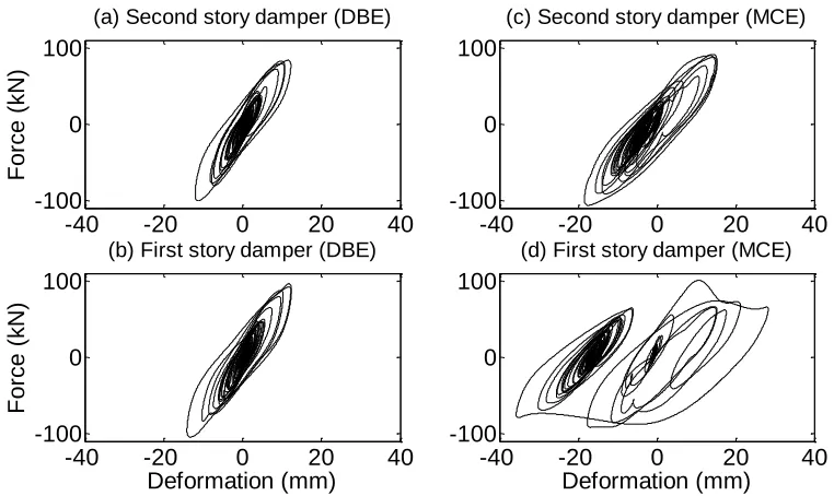
The hysteresis of the compressed elastomer dampers is presented in Fig. 11. The dampers were able to undergo numerous seismic induced deformation cycles without degradation of their hysteretic behavior. Under the DBE the dampers in both stories exhibit an elastomeric behavior with fairly rounded peaks. ((i.e., Figs. 11(a) and 11(b)). Under the MCE the damper in the second story develops some minor slip (Fig. 11(c)), while the damper at the first story experiences an elastomeric-frictional behavior with slip (Fig. 11(d)) that results in permanent deformation, although the damper continues to dissipate energy dissipation. These experimental results can be used to develop and calibrate an analytical model for simulating the complex damper hysteresis.
Fig. 12 shows the floor displacement time histories of the UD50V MRF with dampers. Also presented in Fig. 12 are the floor displacement time history of the conventional UD100V SMRF from numerical analysis. The real-time hybrid simulations show that the lighter UD50V MRF with dampers experiences significantly lower transient and permanent story drifts than those of the conventional UD100V SMRF. Under the DBE earthquake the UD50V MRF with dampers has negligible permanent story drift since the dampers do not slip and have re-centering capability. Under the MCE the dampers act as sacrificial elements, which develop permanent deformation due to slip, however as discussed previously, the dampers can be replaced after the earthquake. Some modest yielding occurs in the beams and at the ground level of the columns of the UD50V MRF with dampers. As will be discussed below, the plastic (and associated permanent) deformations in the MRF with dampers are small. If the dampers were replaced or re-centered after the MCE, the residual drift of the MRF with dampers under the MCE could be significantly reduced.
The added benefit of real-time hybrid simulation is that it allows an unlimited number of ground motions to be applied to the structure and therefore, statistical experimental response results incorporating the ground motion variability can be obtained. In this paper, the seismic performance of the MRF with dampers is quantified in terms of various damage indices for both structural and non-structural components, and include the maximum story drift, θmax; maximum
plastic hinge rotation for beams, θpl.max_bm, and columns, θpl.max_col; peak floor absolute velocity, vmax; peak floor absolute acceleration, amax; and the floor acceleration response spectra, Sa,flr. vmax
and amax are useful for quantifying the potential for damage of rigidly attached
non-structural components and for rigidly attached non-non-structural components, respectively, while
[image:13.612.240.371.74.135.2]Sa,flr is useful for quantifying the potential for damage to flexible attached equipment [36].
Table 4 presents median experimental response values for the θmax, θpl.max_bm, θpl.max_col, vmax and amax of the UD50V MRF with dampers from the real-time hybrid simulations. Also presented in
1.40% for the first and second stories, respectively, for UD50V MRF under the DBE is lower than the anticipated θmax demand of 1.65% given in Table 2, while the median value of 2.60%
and 2.40% for the first and second stories, respectively, the median θmax for the UD100V SMRF
is larger than the anticipated θmax demand of 2.4% given in Table 1. The UD50V MRF with
dampers also shows a significantly better performance than the conventional UD100V SMRF in terms of the plastic hinge rotations. Decreases in the median peak beam plastic hinge rotations in the UD50V MRF with dampers are approximately 75% and 57% for the DBE and MCE, respectively, compared to UD100V SMRF. For the columns, the median peak plastic hinge rotations in the UD50V MRF with dampers are approximately 80% and 33% less than that in the UD100V SMRF for the DBE and MCE, respectively. The median peak floor velocities of the UD50V MRF with dampers are 22% and 31% less at the first and second floors, respectively, than those of the UD100V SMRF for the DBE. For the MCE the median peak floor velocities of the UD50V MRF with dampers are 10% and 14% less at the first and second floors, respectively, than those of the UD100V SMRF The median peak floor accelerations of the UD50V MRF with dampers are 21% and 9% less at the first and second floors, respectively, than those of the UD100V SMRF for the DBE. Under the MCE, the UD50V MRF with dampers experiences a 14% reduction in the first floor median peak acceleration and a slightly higher second floor median peak acceleration than that of the UD100V SMRF.
Fig. 13 shows the median acceleration response spectra Sa,flr of UD50V MRF with
dampers for the DBE and MCE levels. Also presented in Fig. 12 are Sa,flr of the conventional
UD100V SMRF from numerical analysis. These spectra present the maximum pseudo-acceleration response of a 5% damped elastic single-degree-of-freedom system (SDOF) subjected to the motion (total acceleration) of the 2nd floor of the frames. The spectra show that the UD50V MRF with dampers performs significantly better than conventional UD100V SMRF. It is evident that the resonance at the first and second modes of vibration of UD50V MRF with dampers is effectively damped (the period of vibration for the first and second modes are T1 = 1.04 sec. and T2 = 0.35 sec., respectively). Only for a narrow period range (primarily in the period range between the first and second modes) conventional UD100V SMRF shows a slightly better performance than the UD50V MRF with dampers.
6. Summary and conclusions
An experimental program based on the use of real-time hybrid simulation to verify the performance-based seismic design of a steel perimeter MRF equipped with compressed elastomer dampers was presented. The experimental substructures for the simulation consisted of two individual compressed elastomer dampers, with the remainder of the MRF and associated tributary gravity columns and gravity loading of the building modeled as an analytical substructure. Real-time hybrid simulation allowed an ensemble of ground motions to be applied to the structure resulting in various levels of damage, without the need to repair the test specimens, since the damage was within the analytical substructure.
conventional steel MRF. Real-time hybrid simulations showed that the MRF with dampers experiences significantly lower peak story drifts, peak plastic hinge rotations, lower peak absolute floor velocities and floor accelerations in addition to floor spectra accelerations than those of the conventional steel SMRF.
Acknowledgements
This paper is based upon work supported by grants from the Pennsylvania Department of Community and Economic Development through the Pennsylvania Infrastructure Technology Alliance, and by the National Science Foundation (NSF) under Grant No. CMS-04002490 within the George E. Brown, Jr. Network for Earthquake Engineering Simulation Consortium Operation. Any opinions, findings, and conclusions expressed in this paper are those of the authors and do not necessarily reflect the views of the sponsors.
References
[1] Christopoulos C, Filiatrault A. Principles of supplemental damping and seismic isolation. IUSS Press, Milan, Italy, 2006.
[2] Tsai CS, Lee HH. Application of viscoelastic dampers to high-rise buildings. (ASCE)
Journal of Structural Engineering 1993; 119(4):1222-1233.
[3] Kasai K, Munshi JA, Lai ML, Maison BF. Viscoelastic damper hysteretic model: theory, experiment, and application. Proceedings of the ATC 17-1: Seminar on seismic isolation, passive energy dissipation, and active control, 521-532, 1993.
[4] Lee KS. Seismic behavior of structures with dampers made from ultra high damping natural rubber. Ph.D. Dissertation, Department of Civil and Environmental Engineering, Lehigh University, Bethlehem, PA, 2003.
[5] Sause R, Lee KS, Ricles J. Rate-independent and rate-dependent models for hysteretic behavior of elastomers. (ASCE) Journal of Engineering Mechanics 2007; 133(11):1162-1170.
[6] Fu Y, Kasai K. Comparative study of frames using viscoelastic and viscous dampers. (ASCE) Journal of Engineering Mechanics 1998; 124(5): 513-522.
[7] Lee KS, Fan CP, Sause R, Ricles J. Simplified design procedure for frame buildings with viscoelastic or elastomeric structural dampers. Earthquake Engineering and Structural Dynamics 2005; 34:1271-1284.
[8] Lee KS, Ricles J, Sause R. Performance based seismic design of steel MRFs with elastomeric dampers. (ASCE) Journal of Structural Engineering 2009; 135(5): 489-498. [9] Building Seismic Safety Council (BSSC). NEHRP recommended provisions for seismic
regulations for new buildings and other structures, 2003 Ed., Report FEMA 450, Federal Emergency Management Agency, Washington, D.C., 2004.
[10] Ramirez OM, Constantinou MC, Whittaker AS, Kircher CA, Johnson MW, Chrysostomou CZ. Validation of the 2000 NEHRP Provisions’ Equivalent Lateral Force and Modal Analysis Procedures for Buildings with Damping Systems. Earthquake Spectra 2003: 19(4):981-999.
[11] Chang K-C, Lin Y-Y. Seismic response of a full-scale structure with added viscoelastic dampers. (ASCE) Journal of Structural Engineering 2004:130(4):600-608.
passively-controlled 5-story steel building using E-Defense shake table. Part 1: Test concept, method, and building specimen. Proceedings of the sixth international conference on behaviour of steel structures in seismic areas, Philadelphia, Pennsylvania, U.S.A, 16-20 August, 2009.
[13] Ibrahim YE, Marshall J, Charney FA. A visco-plastic device for seismic protection of structures. Journal of Constructional Steel Research 2007; 63:1515-1528.
[14] Karavasilis TL, Sause R, Ricles J. Seismic design of steel MRFs with compressed elastomer dampers.” Earthquake Engineering and Structural Dynamics, accepted for publication.
[15] Sweeney SK, Michael R. Collaborative product realization of an innovative structural damper and application. Proceedings of IMECE2006, ASME International Engineering Congress and Exposition, Chicago, Illinois, USA, 2006.
[16] Pavlou E, Constantinou MC. Response of nonstructural components in structures with damping systems. (ASCE) Journal of Structural Engineering 2006; 132(7):1108-1117. [17] Vargas R, Bruneau M. Effect of Supplemental Viscous Damping on the Seismic
Response of Structural Systems with Metallic Dampers. (ASCE) Journal of Structural Engineering 2007; 133(10):1434-1444.
[18] Wanitkorkul A, Filiatrault A. Influence of passive supplemental damping systems on structural and nonstructural seismic fragilities of a steel building. Engineering Structures
2008; 30:675-682.
[19] Chen C, Ricles JM, Marullo T, Mercan O. Real-time hybrid testing using the unconditionally stable explicit CR integration algorithm. Earthquake Engineering and Structural Dynamics 2009; 38(1):23-44.
[20] Bonnet PA, Lim CN, Williams MS, Blakeborough A, Neild SA, Stoten DP, Taylor CA. Real-time hybrid experiments with Newmark integration, MCSmd outer-loop control and multi-tasking strategies. Earthquake Engineering and Structural Dynamics 2007; 36(1):119-141.
[21] Nakashima M, Kato H, Takaoka E. Development of real-time pseudodynamic testing.”
Earthquake Engineering and Structural Dynamics 1992; 21(1):79-92.
[22] Lehigh RTMD Users Guide. http://www.nees.lehigh.Edu/index.php? page=rtmd–user–s-manual. 2009.
[23] International Code Council (ICC). International Building Code. Falls Church, VA, 2006. [24] SAP2000. Static and Dynamic Finite Element Analysis of Structures. Version 12.0.2.
Computers and Structures Inc., Berkeley, California, 2009.
[25] AISC. Seismic Provisions for Structural Steel Buildings, American Institute of Steel Construction, Chicago, Illinois, 2005.
[26] Sause R, Hemingway GJ, Kasai K. Simplified seismic response analysis of viscoelastic-damped frame structures. Proceedings, 5th U.S. National Conference on Earthquake Engineering, EERI, Chicago, Illinois, Vol. I, 839-848, 1994.
[27] Karavasilis TL, Ricles JM, Marullo T, Chen C. HybriFEM. A program for nonlinear dynamic time history analysis and real-time hybrid simulation of structures. ATLSS Engineering Research Center Report 09-08, Lehigh University, Bethlehem, PA, 2009. [28] MATLAB. A Registered trademark of The Math Works, Inc.,
http://www.mathworks.com, 2007.
UCB/EERC-79/30, 1979.
[30] Chen C, Ricles JM. Development of direct integration algorithms for structural dynamics using discrete control theory. (ASCE) Journal of Engineering Mechanics 2008; 134(8):676-683.
[31] Wallace MI, Sieber J, Neild SA, Wagg DJ, Krauskopf B. Stability analysis of real-time dynamic substructuring using delay differential equation models. Earthquake Engineering and Structural Dynamics 2005; 34(15):1817-1832.
[32] Chen C, Ricles JM. Stability analysis of SDOF real-time hybrid testing systems with explicit integration algorithms and actuator delay. Earthquake Engineering and Structural Dynamics 2008; 37(4):597-613.
[33] Chen C, Ricles JM. Tracking error-based servo-hydraulic actuator adaptive compensation for real-time hybrid simulation.” (ASCE) Journal of Structural Engineering, in press, 2009.
[34] Mercan O. Analytical and experimental studies on large scale, real-time pseudodynamic testing. PhD. Dissertation, Department of Civil and Environmental Eng., Lehigh Univ., Bethlehem, PA, 2007.
[35] Somerville P. Development of ground motion time histories for phase 2 of the FEMA/SAC steel project, Report No. SAC/DB-97/04, Sacramento, CA, 1997.
Table 1. Properties of MRF designs
MRF Column
section Beam sections
Steel weight (KN)
T1
(sec)
Story stiffness
(KN/mm) θmax
(%)
UD100V W14x211 1
st story: W24x84
2nd story: W21x50 200 1.08
1st story: 66574
2nd story: 42018 2.40
UD50V W14x120 1
st
story: W24x55
2nd story: W18x40 124 1.48
1st story: 36007
[image:18.612.146.467.194.277.2]2nd story: 23894 3.23
Table 2. Design properties of UD50V MRF with dampers
α
Brace steel weight
(KN)
β Τ1
(sec) ηd ξt
(%) B
θmax (%)
Nd
Story 1st 2nd
10 17.2 1.0 1.04 0.60 15.00 1.35 1.65 8 5
Table 3. Earthquake ground motions used in real-time hybrid simulations
Earthquake Station Component Magnitude
(Mw)
Distance (km)
PGA (g)
Scale factor
DBE MCE
Loma Prieta 1989 Hollister - S & P HSP090 6.93 27.67 0.18 1.99 2.99
Manjil 1990 Abbar ABBAR--T 7.37 12.56 0.46 0.96 1.44
Northridge 1994 N Hollywood - Cw CWC270 6.69 7.89 0.27 1.70 2.56
ChiChi 1999 TCU105 TCU105-E 7.62 17.18 0.12 2.45 3.67
ChiChi 1999 TCU049 TCU049-E 7.62 3.78 0.29 1.92 2.89
Table 4. Median values of response parameters from real-time hybrid simulations
Design
θmax (%)
θpl.max_bm (rad)
θpl.max_col (rad)
vmax (m/sec)
amax (m/sec2)
DBE MCE DBE MCE DBE MCE DBE MCE DBE MCE
UD100V conventional
SMRF
Story 1 2.60 2.90 0.008 0.014 0.010 0.015 0.78 1.00 5.32 6.60
Story 2 2.40 2.60 0.000 0.003 0.000 0.000 1.11 1.28 5.66 6.36
UD50V MRF with
dampers
Story 1 1.35 2.50 0.002 0.006 0.002 0.010 0.61 0.90 4.18 5.70
[image:18.612.72.548.311.399.2] [image:18.612.81.530.437.557.2]-40 -20 0 20 40 -120
-80 -40 0 40 80 120
Deformation (mm)
F
or
c
e
(k
N)
-40 -20 0 20 40
-120 -80 -40 0 40 80 120
Deformation (mm)
F
or
c
e
(k
N)
(a) (b)
[image:19.612.73.330.72.320.2](c) (d)
Figure 1. Fabrication of compressed elastomer damper: (a) elastomeric material wrapped around longitudinal bar; (b) elastomeric material and bar compressed into the steel tube; (c) damper with additional transverse attachment bars in place and (d) installation to beam web [15]
(a) (b)
[image:19.612.76.545.403.558.2]
0 10 20 30 40 50 0
0.4 0.8 1.2 1.6
Deformation (mm)
eq
f=0.5 Hz f=1.0 Hz f=1.5 Hz f=2.0 Hz f=3.0 Hz
0 10 20 30 40 50
0 4 8 12 16
Deformation (mm)
K eq
(k
N
/m
m
) f=0.5 Hz
f=1.0 Hz f=1.5 Hz f=2.0 Hz f=3.0 Hz
Moment resisting frame
Moment resisting frame
dampers
dampers dampers
dampers
4
.5
7
m
3
.9
6
m
4 @ 9.15m = 36.6m
(a) (b)
Figure 3. Mechanical properties evaluated from characterization tests [14]: (a) equivalent stiffness, and (b) equivalent loss factor
(a)
[image:20.612.74.523.71.233.2](b)
[image:20.612.91.498.279.639.2](W12x 190)
Analytical substructure: structure without dampers
+
2ndstory damper
1st story damper
Experimental substructures: dampers dampers
Total structural system: frame with dampers
Lean-on
column dampers
dampers dampers
dampers
[image:21.612.366.556.212.413.2]Figure 5. Real-time hybrid simulation: analytical and experimental substructures forming the complete structural system
[image:21.612.197.416.473.636.2]N
RTMD Actuator
Dampers
North A-Frame South
A-Frame
Roller Bearings Actuator
Support
Loading Stub
N N
RTMD Actuator
Dampers
North A-Frame South
A-Frame
Roller Bearings Actuator
Support
Loading Stub
(W12x190)
(W12x190)
(a)
[image:22.612.79.264.86.280.2](b)
Figure 7. Compressed elastomer dampers: (a) closeup of damper, and (b) details of test setup for each damper
Damper
0 1 2 3 4 0.0
0.5 1.0 1.5 2.0
Period (sec)
S
a
(
g
)
[image:23.612.196.416.70.241.2]HSP090 ABBAR-T CWC270 TCU105-E TCU049-E
Figure 8. Synchronization subspace with increment of enclosed area dAi(1j) and complementary
enclosed area ( ) 1
j i
[image:23.612.152.454.345.516.2]dTA utilized in the determination of the tracking indicator TI.
Figure 10. Actuator displacement subspace synchronization subspace plots, Loma Prieta 1989 HSP090 ground motion
Figure 11. Damper hysteresis from real-time hybrid simulation, Loma Prieta 1989 HSP090 ground motion
-40 -20 0 20 40
-40 -20 0 20 40
d
c (m
m
)
(a) Second story (DBE)
-40 -20 0 20 40
-40 -20 0 20 40
dm (mm)
d
c (m
m
)
(b) First story (DBE)
-40 -20 0 20 40
-40 -20 0 20 40
(c) Second story(MCE)
-40 -20 0 20 40
-40 -20 0 20 40
dm (mm)
(d) First story (MCE) RMS=1.3e-4
RMS=2.5e-5 RMS=3.7e-4
RMS=3.6e-4
-40 -20 0 20 40
-100 0 100
F
o
rce
(
kN
)
(a) Second story damper (DBE)
-40 -20 0 20 40
-100 0 100
(c) Second story damper (MCE)
-40 -20 0 20 40
-100 0 100
Deformation (mm)
F
o
rce
(
kN
)
(b) First story damper (DBE)
-40 -20 0 20 40
-100 0 100
Deformation (mm)
[image:24.612.109.495.95.329.2] [image:24.612.89.470.418.645.2]0 20 40 60 -0.4
-0.2 0 0.2 0.4
Di
sp
la
ce
m
e
n
t
(m
)
(a) Second floor (DBE)
0 20 40 60
-0.4 -0.2 0 0.2 0.4
(c) Second floor (MCE)
0 20 40 60
-0.4 -0.2 0 0.2 0.4
Time (sec) (d) First floor (MCE)
0 20 40 60
-0.4 -0.2 0 0.2 0.4
Time (sec)
Di
sp
la
ce
m
e
n
t
(m
)
(b) First floor (DBE) UD50V with dampers UD100V
10-1 100 101
0 1 2 3 4
Period (sec)
S
a
(
g
)
UD100V (DBE)
UD50V with dampers (DBE) UD100V (MCE)
UD50V with dampers (MCE)
T
[image:25.612.119.462.98.358.2]2 T1
Figure 12. Floor displacement time histories from the real-time hybrid simulation, Loma Prieta 1989 HSP090 ground motion
[image:25.612.152.460.446.626.2]

![Figure 2. Damper hysteresis from characterization tests [14]: (a) before slip, and (b) after slip](https://thumb-us.123doks.com/thumbv2/123dok_us/9663635.468315/19.612.73.330.72.320/figure-damper-hysteresis-characterization-tests-slip-b-slip.webp)