Predictive Control for Active Split DC-bus
4-leg Inverters
S. Bifaretti, S. Pipolo
Dept. of Industrial Engineering University of Rome Tor Vergata C-PED, Center for Power Electronics
and Drives Rome, Italy [email protected]
A. Lidozzi, L. Solero
Dept. of Engineering Roma Tre University
C-PED, Center for Power Electronics and Drives
Rome, Italy [email protected]
L. Tarisciotti, P. Zanchetta
Dep. of Electrical and Electronic Engineering
University of Nottingham, Nottingham, U.K. [email protected]
Abstract - This paper proposes a Predictive Control, formally Dead-Beat (DBC), for a four-leg inverter having an Active Split DC-bus on the fourth leg and LC filters on phase-to-neutral outputs. Such a configuration permits to reduce the voltage ripple on the neutral point connected to inverter grounding. As only few control techniques have been investigated for Active Split DC-bus, the paper proposes to investigate the performance of DBC, which has been widely used for other power electronics applications. The main advantage of DBC over the classical PI or Resonant controller is that no tuning is required for control loop, while obtaining very fast transient response as well it can handle general constrained nonlinear systems with multiple inputs and outputs in a unified and clear manner. These features are highly valuable in power electronic converters used to supply the electrical utility loads in micro-grids. However, one of the main drawback of the DBC is the limited capabilities on harmonics compensations required when supplying unbalanced and non-linear loads. The paper presents continuous-time and discrete-time models of DBC applied to a four-leg VSI with Active Split DC-bus, highlighting the performance through simulation results as well as experimental tests.
I. INTRODUCTION
Voltage Source Inverter (VSI) topology is finding increasing utilization in the supply of electrical utility systems due to the widespread use of UPS and active filtering units, for an improved quality of the energy supply, as well as in the growing use of renewable energy resources in distributed generating systems. These may be arranged in form of micro-grid with common DC-bus, as schematically depicted in Fig. 1. In such applications, the output inverter is used to supply the electrical utility loads, which can be either single or three phase loads and, in the case of three-phase loads, they can be either balanced or unbalanced. Hence, a four-wire electrical distribution system must be arranged for the supply of such utility loads and to this goal, a stable and ripple-free neutral connection must be provided, in order to avoid recirculation of currents through the system stray capacitances, in particular when the TT grounding arrangement is used.
In the case of the four-leg VSI topology several configurations are offered, one approach relies on simply adding a fourth leg in the conventional VSI layout so that the middle point of such switching leg is directly used as the inverter N terminal. Alternatively, a filtering inductor is placed between the output N- terminal and the active phase-leg. Such an arrangement
allows that the neutral wire is stabilized with respect to the fundamental frequency, but a significant voltage ripple still affects the waveform of the voltages measured between the N point and the DC-plus and DC- minus bars. The high frequency oscillations occur at the switching frequency and its related multiple values, so that issues may arise concerning the grounding arrangement (i.e. TT or TN) adopted for the utility system. When TN arrangement is used, this leads to recirculating currents on the DC-Link side system, in particular through large surface PV units; instead, when TT system is used, high common mode voltage arises at the load-side, leading to possible malfunctions of end- user equipment.
strategy are evaluated through an accurate simulation model and then validated by experimental tests.
[image:2.595.60.279.274.381.2]Fig. 1. Typical application of the front-end inverter.
[image:2.595.320.538.369.613.2]Fig. 2. VSI 4-leg topology with Active Split DC-bus.
Fig. 3. Phase-to-neutral scheme of output power filter.
II.SYSTEMMODEL
The VSI Inverter model can be described by the following differential equations:
݀݅௫ሺݐሻ
݀ݐ ൌ
ͳ ܮ
ൣെܴ݅௫ሺݐሻ ݒ௩௫ሺݐሻ െ ݒ௫ேሺݐሻ൧ ൌ
ൌ ͳ
ܮൣെܴ݅௫ሺݐሻ ܵଵ௫ݒଵሺݐሻ െ ܵଶ௫ݒଶሺݐሻ െ ݒ௫ேሺݐሻ൧ ݀ݒ௫ேሺݐሻ
݀ݐ ൌ
ͳ ܥ௫
ൣ݅௫ሺݐሻ െ ݅௫ሺݐሻ൧
(1) being x=a, b, c one of the three inverter phases, ifx the
filter current, Rf the parasitic resistance of filter inductor,
vinvx, the inverter Phase-to-Neutral voltage,vxN the
phase-to-Neutral output voltage, S1x and S2x the switching
functions, for the upper and lower leg switches respectively. The switching functions assume a value equal to 1, when the corresponding switch is closed, or equal to 0 in the opposite case.
The DC-link Voltage, assumed as a constant and the neutral current in are subject to the following constrains:
ܸൌ ݒଵሺݐሻ ݒଶሺݐሻ (2)
݅ሺݐሻ ൌ െ൫݅ሺݐሻ ݅ሺݐሻ ݅ሺݐሻ൯ (3)
Using the same approach as for Inverter model, the neutral leg n with Active Split DC-bus model can be described by defining the differential equations:
ௗሺ௧ሻ
ௗ௧ ൌ
ଵ
ൣെܴ݅ሺݐሻ ܵଵݒଵሺݐሻ െ ܵଶݒଶሺݐሻ൧
ௗ௩మሺ௧ሻ
ௗ௧ ൌ
ଵ
భାమൣ݅ሺݐሻ െ ݅ሺݐሻ൧
(4) being ௗ௩భሺ௧ሻ
ௗ௧ ൌ െ
ௗ௩మሺ௧ሻ
ௗ௧ from (2).
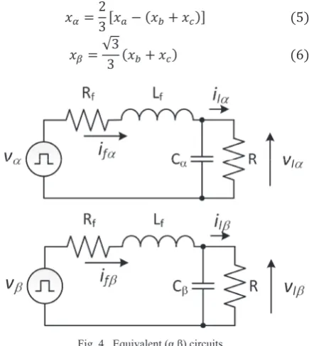
In order to permit a separate control of the fourth leg and, as a consequence, reduce the computational complexity, an equivalent model in fixed reference frame (Į, ȕ) is considered. Using the Clarke’s transformations in (5) and (6), the equivalent (Į ,ȕ) models shown in Fig. 4, being x the inverter voltage or the filter current, the equivalent (Į ,ȕ) models shown in Fig. 4, are obtained.
ݔఈൌʹ
͵ሾݔെ ሺݔ ݔሻሿሺͷሻ
ݔఉ ൌ ξ͵
͵ ሺݔ ݔሻሺሻ
Fig. 4. Equivalent (Į,ȕ) circuits.
The voltages produced by the VSI are related to the switching states and the DC-Link voltage VDC according
to the following equations:
ݒఈሺݐሻ ൌ ܵఈሺݐሻܸሺሻ
ݒఉሺݐሻ ൌ ܵఉሺݐሻܸሺͺሻ
Consequently, the VSI can produce on the (Į, ȕ) plane, six active vectors and two zero vectors. SĮ and Sȕ
represent the normalized amplitude of voltage vectors components related to the switching configurations, as shown in Table I.
B C A
N C2
Lf, Rf
C1
C
OUTPUT FILTER
ifa
ifc
ia
ic
in
vC1
vC2
in
VDC
ifn
+
-S1
S2
S3 S5 S7
[image:2.595.59.279.419.479.2]TABLE I. SWITCHING STATES AND EQUIVALENT (Į,ȕ) COMPONENTS
S S1 / S2 S3 / S4 S5 / S6 Sɲ Sɴ
0 0 / 1 0 / 1 0 / 1 0 0
1 1 / 0 0 / 1 0 / 1 2Ш3 0
2 1 / 0 1 / 0 0 / 1 1Ш3 я3Ш3
3 0 / 1 1 / 0 0 / 1 -1Ш3 я3Ш3
4 0 / 1 1 / 0 1 / 0 -2Ш3 0
5 0 / 1 0 / 1 1 / 0 -1Ш3 -я3Ш3
6 1 / 0 0 / 1 1 / 0 1Ш3 -я3Ш3
7 1 / 0 1 / 0 1 / 0 0 0
According to the (Į ,ȕ) representation shown in Fig. 4, the following continuous-time model can be written:
ە ۖ ۖ ۖ ۔ ۖ ۖ ۖ ۓ݀݅ఈሺݐሻ
݀ݐ ൌ
ͳ
ܮ݂ሾݒ௩ఈሺݐሻ െ ݒఈሺݐሻሿ െ ܴ
ܮ݂ ݅ఈሺݐሻ
݀݅ఉሺݐሻ
݀ݐ ൌ
ͳ
ܮ݂ൣݒ௩ఉሺݐሻ െ ݒఉሺݐሻ൧ െ ܴ
ܮ݂݅ఉሺݐሻ ݀ݒఈሺݐሻ
݀ݐ ൌ
ͳ
ܥ݂ൣ݅ఈሺݐሻ െ ݅ఈሺݐሻ൧ ݀ݒఉሺݐሻ
݀ݐ ൌ
ͳ
ܥ݂ൣ݅ఉሺݐሻ െ ݅ఉሺݐሻ൧
ሺͻሻ
A discrete-time model is achieved from (9) assuming that the system variables are constant during the sampling interval Ts.
ە ۖ ۔ ۖ
ۓ݅ఈሺݐ ܶ௦ሻ ൌ ܭଵ݅ఈሺݐሻ ܭଶሾݒ௩ఈሺݐሻ െ ݒఈሺݐሻሿ ݅ఉሺݐ ܶ௦ሻ ൌ ܭଵ݅ఈሺݐሻ ܭଶൣݒ௩ఉሺݐሻ െ ݒఉሺݐሻ൧
ݒఈሺݐ ܶ௦ሻ ൌ ݒఈሺݐሻ ܭଷൣ݅ఈሺݐሻ െ ݅ఈሺݐሻ൧
ݒఉሺݐ ܶ௦ሻ ൌ ݒఉሺݐሻ ܭଷൣ݅ఉሺݐሻ െ ݅ఉሺݐሻ൧ ሺͳͲሻ
where tk is the actual sampling instant, ݒ௩ఈ and ݒ௩ఉ are the average voltage components produced by the converter calculated in the previous sampling time, and K1, K2 are two constants defined as:
ܭଵൌ ݁ ିೃ
ܮ்݂ೞൎ ͳ െோ
ܮ݂ܶ௦
ܭଶൌ ଵ ோ൭ͳ െ ݁
ିೃ
ܮ்݂ೞ൱ ൎ்ೞ ܮ݂
ܭଷൌ ܶ௦
ܥ݂
[image:3.595.323.521.180.664.2]III.PROPOSED PREDICTIVE CONTROL
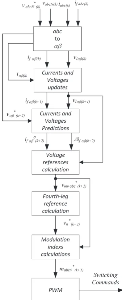
Fig. 5 shows the block scheme of the proposed Predictive Controller for the 4-leg Active Split DC bus VSI. The control strategy aim to perform separate control between the three-phase VSI and the fourth leg avoiding complex modulation strategies [12]. In order to obtain a constant switching frequency required for an effective output filtering, a predictive dead-beat control strategy has been chosen for the VSI.
Dead-Beat control [13], [14] is a model-based strategy which performs, at every sampling interval, the prediction of the system response to a modification in the controlled variables in order to achieve a near zero error usually in the next sampling period. In practical implementations the computational time has to be compensated, to avoid affecting the control action, with one sampling interval delay. To compensate for such a delay, the two step prediction proposed in [15] is used.
if abc(k)
v * (k+2)
Switching Commands iabc(k)
vabcN(k)
abc to
if (k) vl (k)
Currents and Voltages
updates
if (k+1) vl (k+1)
Currents and Voltages Predictions
Voltage references calculation
if (k+2) if (k+2)
vinv abc*(k+2)
i (k)
Fourth-leg reference calculation
Modulation indexs calculations
PWM vn *(k+2)
mabcn *(k+1)
[image:3.595.58.250.250.360.2]vabcN*(k)
Fig. 5. Block diagram of the proposed controller.
The determination of the output reference voltages vinvxabc*(tk+2 Ts) is achieved based on the contributions
of the free and forced evolution.
The currents predictions (10) can be written as: ݅ఈሺݐ ʹܶ௦ሻ ൌ ݅ఈሺݐ ʹܶ௦ሻ ܭଶܸ௩ఈሺݐ ܶ௦ሻ
where݅ఈǡ݅ఉare the contributions of the free evolution of output filter current:
݅ఈሺݐ ʹܶ௦ሻ ൌ ܭଵ݅ఈሺݐ ܶ௦ሻ െ ܭଶݒఈሺݐሻ
݅ఉሺݐ ʹܶ௦ሻ ൌ ܭଵ݅ఈሺݐ ܶ௦ሻ െ ܭଶݒఉሺݐሻ
The contribution of forced evolution can be achieved by computing, for each component, the amount of current that shall flow in the inductor filter to reach the desired references݅ఈכሺݐ ʹܶ௦ሻǡ ݅ఉכሺݐ ʹܶ௦ሻǤ
The current errors ο݅ఈכሺݐ ʹܶ௦ሻǡ ο݅ఉכሺݐ ʹܶ௦ሻ are calculated as the difference between the current references and the currents produced from the zero vectors:
ο݅ఈሺݐ ʹܶ௦ሻ ൌ ݅ఈכሺݐ ʹܶ௦ሻ െ ݅ఈሺݐ ʹܶ௦ሻ
ο݅ఉሺݐ ʹܶ௦ሻ ൌ ݅ఉכሺݐ
ʹܶ௦ሻ െ ݅ఉሺݐ ʹܶ௦ሻ
Considering the control working properly is possible to assume:
ە ۖ ۔ ۖ
ۓ݅ఈሺݐ ʹܶ௦ሻ ൌ ݅ఈ כሺݐ
ʹܶ௦ሻ
݅ఉሺݐ ʹܶ௦ሻ ൌ ݅ఉכሺݐ ʹܶ௦ሻ ݒఈሺݐ ʹܶ௦ሻ ൌ ݒఈכሺݐ
ʹܶ௦ሻ ݒఉሺݐ ʹܶ௦ሻ ൌ ݒఉכሺݐ ʹܶ௦ሻ
ሺͳͳሻ
Therefore, the current references are computed by inverting the 3rd the 4th of (10) together with assumptions (11):
݅ఈכሺݐ ʹܶ௦ሻ ൌ ݅ఈሺݐ ܶ௦ሻ ௩ഀכሺ௧ೖାଶ்ೞሻି௩ഀሺ௧ೖାଶ்ೞሻ
య
݅ఉכሺݐ ʹܶ௦ሻ ൌ ݅ఉሺݐ ܶ௦ሻ
௩ഁכሺ௧ೖାଶ்ೞሻି௩ഁሺ௧ೖାଶ்ೞሻ
య
The converter voltage references in (Į ,ȕ) reference frame are finally obtained as:
ݒ௩ఈכሺݐ ʹܶ௦ሻ ൌ ݒఈሺݐ ܶ௦ሻ
ο݅ఈሺݐ ʹܶ௦ሻ ܭଶ
ݒ௩ఉכሺݐ
ʹܶ௦ሻ ൌ ݒఉሺݐ ܶ௦ሻ
ο݅ఉሺݐ ʹܶ௦ሻ ܭଶ
Applying the inverse Clarke’s transformation to the last relations, the references for the three output voltages vinvxa*(tk+2Ts), vinvxb*(tk+2Ts), vinvxc*(tk+2Ts) can be
achieved.
In order to maintain the benefit in terms of harmonic content of the conventional three-phase VSI feeding a star-connected balanced load, a proper zero-sequence signal vn*(tk+2Ts) has to be used as a reference to control
the fourth-leg. The most common and effective solution, adopted in this paper, is based on the following relationship [16]:
(
)
(
)
* * *
max
* * *
min
max , ,
min , ,
an bn cn
an bn cn
D v v v
D v v v
= =
* max min
2
n
D D
v = − −
In order to use a triangular waveform for the neutral voltage vn with the Active Split DC-bus configuration
and avoids the negative effects produced by interaction of the neutral voltage harmonics and the Active Split filter, the resonance frequency of the filter shall be selected 1 decade higher than the injected harmonic frequency, as highlighted in [17].
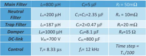
[image:4.595.310.544.254.345.2]SIMULATION AND EXPERIMENTAL RESULTS The proposed control strategy, has been verified, at first, by a specific simulation model developed in PLECS employing the parameters listed in Table II.
TABLE II. OPERATING CONDITIONS
Main Filter Lf=800 μH Cf=5 μF ZĨ = 50mΩ Neutral
Filter Ln=200 μH C1=C2=2.35 μF Rn = 10mΩ Trap Filter Lt=187 μH Ct=2×0.47 μF Rt=20 mΩ
Damper Ld=1000 μH Cd=8.1 μF Rd=15 Ω
DC-link Vdc=700 V Cdc=800 μF
Control Ts= 8.33μs fs= 12 kHz Time step =
Ts /100
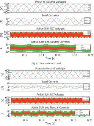
Fig. 6 shows the behavior of the converter in the case of an unbalanced 3-phase resistive load (1kW, 2kW, 2kW on each of the three phases respectively) whilst, in Fig. 7, the waveforms are referred to unbalanced and non-linear load case when a single-phase diode rectifier load is applied on phase a. The phase-to-neutral voltages waveforms present a good harmonic content with a THD value equal to about 2% for resistive unbalanced load and to about 5% for non-linear unbalanced load, thus compliant to the limits imposed by the standard IEC 61000-3-2..
Fig. 6. Linear unbalanced load.
[image:5.595.90.266.529.674.2]Fig. 7. Nonlinear single phase diode rectifier load.
Fig. 8. Four-leg VSI converter prototype. Fig. 9. Inverter output power filter.
[V]
[A
]
[V]
A
[V]
[A]
[V]
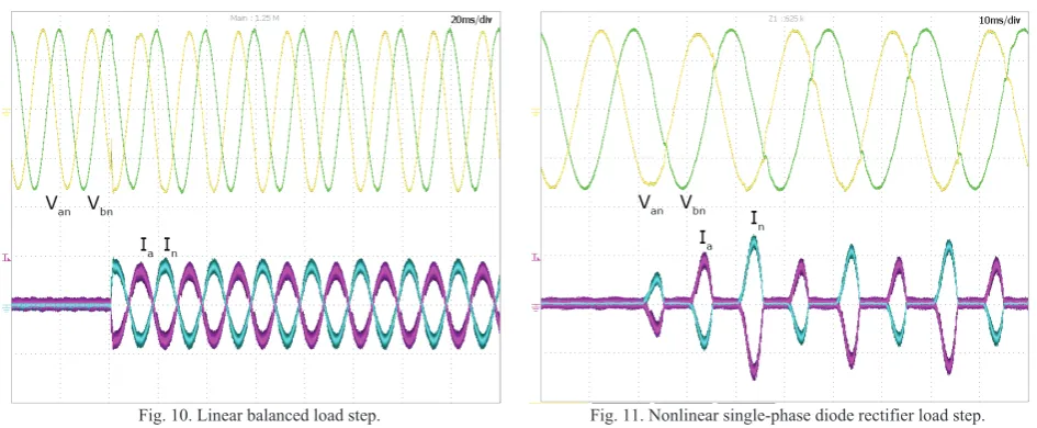
Fig. 10. Linear balanced load step. (20 A/div, 200 V/div)
Fig. 11. Nonlinear single-phase diode rectifier load step. (50 A/div, 200 V/div)
CONCLUSIONS
The paper investigates the application of the Dead-Beat strategy to control a 4-leg VSI having an Active Split DC-bus on the fourth leg and used to supply both unbalanced and non-linear electrical utility loads in a micro-grid. A detailed description of the discrete-time model, even useful for a practical implementation on Microprocessor, has been presented. Compared to high performance Resonant Controllers, the Predictive Controller has the certain advantage to do not require any tuning of regulator gains; on the other hands, it exhibits a lower harmonic compensation capability.
REFERENCES
[1] A. Lidozzi, G. L. Calzo, S. Pipolo, L. Solero, and F. Crescimbini, “Modeling of voltage source inverter having active split DC-bus for supply of four-wire electrical utility systems,” in Energy Conversion Congress and Exposition (ECCE), 2014 IEEE, 2014, pp. 1043–1050. [2] G. Lo Calzo, A. Lidozzi, L. Solero, and F. Crescimbini, “LC Filter Design for On-Grid and Off-Grid Distributed Generating Units,” IEEE Trans. Ind. Appl., vol. 51, no. 2, pp. 1639–1650, Mar. 2015. [3] M. Rivera, V. Yaramasu, A. Llor, J. Rodriguez, B. Wu, and M. Fadel, “Digital Predictive Current Control of a Three-Phase Four-Leg Inverter,” IEEE Trans. Ind. Electron., vol. 60, no. 11, pp. 4903–4912, Nov. 2013.
[4] V. Yaramasu, M. Rivera, M. Narimani, B. Wu, and J. Rodriguez, “Model Predictive Approach for a Simple and Effective Load Voltage Control of Four-Leg Inverter With an Output LC Filter,” IEEE Trans. Ind. Electron., vol. 61, no. 10, pp. 5259–5270, Oct. 2014.
[5] P. Cortes, A. Wilson, S. Kouro, J. Rodriguez, and H. Abu-Rub, “Model Predictive Control of Multilevel Cascaded H-Bridge Inverters,” IEEE Trans. Ind. Electron., vol. 57, no. 8, pp. 2691–2699, Aug. 2010.
[6] B. S. Riar, T. Geyer, and U. K. Madawala, “Model Predictive Direct Current Control of Modular Multilevel Converters: Modeling, Analysis, and Experimental Evaluation,” IEEE Trans. Power Electron., vol. 30, no. 1, pp. 431–439, Jan. 2015.
[7] M. Preindl and S. Bolognani, “Model Predictive Direct Speed Control with Finite Control Set of PMSM Drive Systems,” IEEE Trans. Power Electron., vol. 28, no. 2, pp. 1007–1015, Feb. 2013. [8] M. Parvez Akter, S. Mekhilef, N. Mei Lin Tan, and H. Akagi, “Modified Model Predictive Control of a Bidirectional AC-DC Converter Based on Lyapunov Function for Energy Storage Systems,” IEEE Trans. Ind. Electron., vol. 63, no. 2, pp. 704–715, Feb. 2016. [9] M. Rivera, V. Yaramasu, A. Llor, J. Rodriguez, B. Wu, and M. Fadel, ‘‘Digital predictive current control of a three-phase four-leg
inverter,’’ IEEE Trans. Ind. Electron., vol. 60, no. 11, pp. 4903---4912, Nov. 2013.
[10] L. Tarisciotti, P. Zanchetta, A. Watson, S. Bifaretti, and J. C. Clare, “Modulated Model Predictive Control for a Seven-Level Cascaded H-Bridge Back-to-Back Converter,” IEEE Trans. Ind. Electron., vol. 61, no. 10, pp. 5375–5383, Oct. 2014.
[11] L. Tarisciotti, P. Zanchetta, A. Watson, J. C. Clare, M. Degano, and S. Bifaretti, “Modulated Model Predictive Control for a Three-Phase Active Rectifier,” IEEE Trans. Ind. Appl., vol. 51, no. 2, pp. 1610–1620, Mar. 2015.
[12] R. Zhang, V. H. Prasad, D. Boroyevich, F. C. Lee, “Three Dimensional Space Vector Modulation for Four-Leg Voltage-Source Converters”, IEEE Trans. Power Electron., vol. 17, no. 3, pp. 314-326, Mar. 2002.
[13] V. Biagini, M. Odavic, P. Zanchetta, M. Degano, and P. Bolognesi, “Improved dead beat control of a shunt active filter for aircraft power systems,” in IEEE International Symposium on Industrial Electronics (ISIE), 2010, pp. 2702–2707.
[14] S. Bifaretti, P. Zanchetta, A. J. Watson, L. Tarisciotti, and J. C. Clare, “Advanced power electronic conversion and control system for universal and flexible power management,” IEEE Trans. Smart Grid, vol. 2, no. 2, pp. 231–243, 2011.
[15] L. Tarisciotti, A. J. Watson, P. Zanchetta, S. Bifaretti, J. C. Clare, and P. W. Wheeler, “An improved Dead-Beat current control for Cascaded H-Bridge active rectifier with low switching frequency,” in IET International Conference onPower Electronics, Machines and Drives (PEMD), 2012, pp. 1–6.
[16] J-H. Kim, S-K. Sul, “A Carrier-Based PWM Method for
Three-Phase Four-Leg Voltage Source Converters”, IEEE Trans. Power Electron., vol.19, no.1, pp. 66-75, Jan. 2004.