warwick.ac.uk/lib-publications
Original citation:
Konstantinov, Sergey, Ahmad, Mussawar, Ananthanarayan, Karthik and Harrison, Robert.
(2017) The cyber-physical e-machine manufacturing system : virtual engineering
for complete lifecycle support. Procedia CIRP .
Permanent WRAP URL:
http://wrap.warwick.ac.uk/88346
Copyright and reuse:
The Warwick Research Archive Portal (WRAP) makes this work of researchers of the
University of Warwick available open access under the following conditions.
This article is made available under the Attribution-NonCommercial-NoDerivatives 4.0 (CC
BY-NC-ND 4.0) license and may be reused according to the conditions of the license. For
more details see: http://creativecommons.org/licenses/by-nc-nd/4.0/
A note on versions:
The version presented in WRAP is the published version, or, version of record, and may be
cited as it appears here.
ScienceDirect
Procedia CIRP 00 (2017) 000–000
www.elsevier.com/locate/procedia
2212-8271 © 2017 The Authors. Published by Elsevier B.V.
Peer-review under responsibility of the scientific committee of The 50th CIRP Conference on Manufacturing Systems.
The 50th CIRP Conference on Manufacturing Systems
The Cyber-Physical e-machine Manufacturing System: Virtual Engineering
for Complete Lifecycle Support
Sergey Konstantinov*, Mussawar Ahmad, Karthik Ananthanarayan, Robert Harrison
aAutomation Systems Group, WMG, University of Warwick, CV4 7AL, Coventry, West Midlands, UK
* Corresponding author. Tel.: +44 (0) 2476 573413;. E-mail address: [email protected]
Abstract
Electric machines (machines) will form a fundamental part of the powertrain of the future. Automotive manufacturers are keen to develop e-machine manufacturing and assembly knowledge in-house. An on-going project, which aims to deliver an e-e-machine pilot assembly line, is being supported by a set of virtual engineering tools developed by the Automation Systems Group at the University of Warwick. Although digital models are a useful design aid providing visualization and simulation, the opportunity being exploited in this research paper is to have a common model throughout the lifecycle of both the manufacturing system and the product. The vision is to have a digital twin that is consistent with the real system and not just used in the early design and deployment phases. This concept, commonly referred to as Cyber Physical Systems (CPS), is key to realizing efficient system reconfigurability to support alternative product volumes and mixes. These tools produce modular digital models that can be rapidly modified preventing the simulation, test, and modification processes forming a bottleneck to the development lifecycles. In addition, they add value at more mature phases when, for example, a high volume line based on the pilot is created as the same models can be reused and modified as required. This research paper therefore demonstrates how the application of the virtual engineering tools support the development of a CPS using an e-machine assembly station as a case study. The main contribution of the work is to further validate the CPS philosophy by extending the concept into practical applications in pilot production systems with prototype products.
© 2017 The Authors. Published by Elsevier B.V.
Peer-review under responsibility of the scientific committee of The 50th CIRP Conference on Manufacturing Systems.
Keywords: digital manufacturing; virtual engineering; assembly automation; electric machines
1.Introduction
The electrification of automotive powertrains is imposed upon the industry due to concerns with climate change, the depletion of fossil fuel reserves, and the health and environmental impacts of combustion. The electric powertrain requires the development of enabling technologies for its realisation including: batteries, e-machines, efficient power convertors, and power management software. This paper focuses on the manufacture and assembly of e-machines through an industry led project named: High Volume E-Machine Supply from the UK (HVEMS-UK) [1]. The objective of the project is to better understand the challenges of manufacturing e-machines at the anticipated volumes by building and commissioning a Make-Like-Production (MLP) facility.
2 Author name / Procedia CIRP 00 (2017) 000–000
configuration and layouts, and process planning, but then extend to the commissioning, maintenance, operation, and re-engineering/re-configuration of the system [4].
One of the major challenges within the area of CPS is the lack of engineering tools and methods that support in its implementation. Therefore, the value and the resulting business benefits have not been demonstrated fully, slowing industrial uptake. Thus, within this paper, the authors demonstrate how an engineering workflow that utilizes CPS enabled engineering tools complement the engineering process and more traditional toolsets and methods.
2.Literature Review
2.1.Automation system lifecycle tools
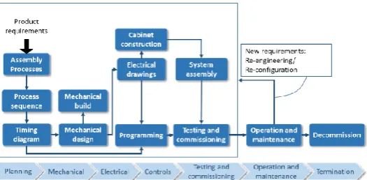
The lifecycle of an automation system is described in Fig 1. There are number of methods to support each of the phases using digital engineering tools and/or paper-based standards. The former typically includes of Computer Aided Design (CAD) and Computer Aided Engineering (CAE) modelling tools such as SOLIDWORKS for mechanical aspects, and EPLAN for electrical wiring and cabinet design [5, 6] . A
solution from Siemens, Process Simulate, enables
manufacturing process verification in a 3D environment [7]. Another digital manufacturing solution set from Dassault Systems, DELMIA V5, provides design of manufacturing processes, tools, and fixtures [8]. The capabilities of this toolkit have been extended in V6 to support better integration of system data [9]. However, the offerings from such software developers are heavyweight, expensive, and cannot typically be employed through the supply chain to enable engineering concurrency and collaboration [10]. Typical paper-based standards that support the lifecycle include IEC 60812 [11] for assessing reliability through formal failure modes effects analysis, and the machinery directive 2006/42/EC [12] to maintain a consistent safety standard across EU member states. By the term paper-based, the authors refer to the fact that the documentation associated with meeting these standards are not integrated with the engineering models, despite their importance, and are created within less formal environments such as word processors or spreadsheets.
2.2.Digital Factory and Digital Twin
Westkämper and Jendoubi introduced the concept of the Digital Factory to support in the broader vision of the “Smart Factory” [13]. They specify that the Digital Factory should include geometric models to visualise integrated behavioural models to simulate systems. Further, the virtual and physical worlds should be fused into a single environment. Data flows from physical systems to virtual models to improve consistency, which in turn inform optimization strategies for the real system, supporting the production system through its lifecycle [13].
Typically, virtual system components and simulations are executed without the integration of physical automation devices and components e.g. virtual machine behavior is not validated with physical Programmable Logic Controllers
(PLCs) [14]. Virtual Commissioning is one example of the benefits of integrating virtual models with the physical system. Practical engineering workflows in industrial applications have been demonstrated by Daimler AG and the University of Magdeburg that utilizing a string of engineering tools, methods, and standards including: Siemens NX Mechatronics Concept Designer, envision, WinMOD, Functional Mockup Interfaces, and AutomationML [15-18]. These workflows consist of the elements described by [13] related to the definition of geometry, kinematics and system inputs/outputs (I/Os) to model behaviours [19]. AutomationML, an XML schema based data format, is able to facilitate collaboration between engineering tools in different disciplines, such as: mechanical and electrical design, process engineering, control
engineering, robot programming and HMI development [20].
Brusaferri in [21] discusses the extension of CPS functionalities with the help of defining a “Virtual Avatar” as a counterpart of a physical system. The CPS Avatar is considered to be a virtual twin of the physical part of the CPS. It is expected to support the optimization of the runtime performance of CPS through algorithms that, upon validation within simulations, go on to control their real-time behavior. In a similar vein, Weyer discusses the Digital Twin concept for data exchange between CPS and tools aiming to improve the design, engineering, and management of future CPS-based factories [22]. Wang et al. discuss the definition of CPS within a manufacturing context and elaborate through a number of examples, illustrating how
businesses and customers can benefit through its
implementation [23]. However, more recently Monostori et al. highlight one of the challenges of CPS to be the fusion of real and virtual systems [24].
2.3.Summary
Despite many descriptions of the potential benefits of CPSs supported by Digital Factories or Digital Twins, engineering tools to aid this vision remain disjointed. Engineering data exists in silos, and while there is activity to move towards more
integrated approaches i.e. AutomationML, the lack of
practically implementable workflows supported by
[image:3.595.303.566.69.198.2]engineering tools remains a problem. There is a need for an open, integrated tool chain that can support design, simulation, virtual commissioning and further stages of the system lifecycle described in Fig.1 from early concepts to reconfiguration [4].
3.Methodology
3.1.Virtual Engineering Tools
This research utilizes a set of virtual engineering tools developed by the Automation Systems Group at the University of Warwick to support the lifecycle of the production system called vueOne. The engineering tools are built upon a “component-based” philosophy. This means that data is encapsulated within a software component that can exist at a level of granularity defined by the user. The component is extensible and can therefore accommodate new data that may not have been considered at a given engineering phase. Moreover, each component has a unique ID. These IDs can be used in the engineering phase to manage components within a database. In addition, they can be used to contextualize the large amount of operational data generated by a system by linking it to specific physical components to support data collection for monitoring, analytics, and optimization. The component can be stored within a library and called into a system during the design phase of a different system, or to make changes to an existing one. The geometrical data for
components is converted from neutral CAD formats i.e. STEP
to VRML to allow a web-based collaborative engineering approach. Process planning is executed through state transition diagrams (STDs) that are compliant with IEC 61499 and so PLC code can be automatically generated and deployed to support virtual commissioning. A detailed description of the tools can be found in [4].
3.2.Workflow for engineering CPS
One of the major challenges associated with the engineering and build of a real system are the large number of domains of expertise that must be involved. These include the engineering specialisms e.g. mechanical, electrical, controls, and system integration, and other areas of the business such as management, finance, and procurement. Furthermore, stakeholders also exist outside of the business such as the supply chain. Each of these areas utilize their own tools, methods, and language and it is necessary to complement these. Imposing an approach across a large, complex project results in the formation of adversarial relationships that contribute negatively to productivity. It is therefore important to maintain existing workflows, but complement and enrich them with the CPS vision.
Fig. 2 describes the production system lifecycle that is supported by the CPS paradigm using the vueOne toolset. As highlighted in the literature review, commercially available engineering tools with similar capabilities to vueOne are often heavyweight, monolithic, and expensive. Thus, sharing engineering models with the aforementioned stakeholders incur delays and costs that consume valuable engineering time and resources. This is often attributed to complex features, installation procedures, and licensing models. To overcome this, the vueOne viewer is used to share models and simulations at different stage of the development lifecycle to ensure that ideas are being communicated effectively at all levels of the business and through the supply chain. This allows
stakeholders to buy into concepts in a more effective way than conventional, fragmented practice, and maintains consistency through the development lifecycle.
At the more granular, detailed engineering of systems, the various components and subsystems are exported from the engineering tools of machine builders into the vueOne engineering tools. The respective model can be added or replaced into the common virtual engineering model (often a crude initial model may be retained as an artifact of the concept development phase) and the associated processes and behaviours are reintroduced. This enables validation of configurations and process plans. In addition, the toolset has the capability to model humans through the V-Man (virtual manikin) module and robot behavior through the V-Rob (virtual robot) module. These important elements of a production system can exist within the common model so their interaction can be visualized and assessed to improve and optimize processes and layouts.
The V-man module utilises an intuitive posture
manipulation interface and move sequence behavior is represented through a STD that can be fully integrated to the wider system behavior through a form of interlock logic. The
V-man is calibrated through MODular Arrangement of
Predetermined Time Standards (MODAPTS) [25] which is a type of Predetermined Motion Time System (PMTS) [4]. The
V-Rob module emulates robot behavior and complements
commercial offline programming tools such as ABB’s RobotStudio through interfaces to import/export spatial and temporal robot behavior information.
Retention of domain specific engineering tools negates the need to train engineers on using new tools. Considerably more detailed complementary information that exists within such specialist engineering tools, and only what is deemed necessary is brought into the common model. This results in a lightweight model. The common model can then be used later in the lifecycle of the production system to support in virtual
[image:4.595.305.567.68.326.2]4 Author name / Procedia CIRP 00 (2017) 000–000
commissioning through the vueOne mapper module. This module maps components, PLC function blocks, I/O, and memory addresses, as well as storage and version management of the mapping information.
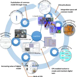
Beyond the commissioning phase, the lightweight engineering models come into their own as runtime connections through an OPC-UA client that can retrieve data from the physical system and map it to the corresponding virtual component. A standard OPC-UA server is used as it provides access to drivers for a variety of PLCs. This ability to capture runtime data with contextual information is exploited
through web-based mobile apps allow monitoring,
maintenance, and optimisation with respect to enterprise specific key performance indicators. Figure 3 illustrates that pathways to realizing the digital twin through the engineering tools.
4.Case Study
As aforementioned, the case study within this paper demonstrates the use of the vueOne toolset to realise the magnet insertion process that places magnets inside the rotor. The rotor is built using a lamination process that is a pre-assembled component fed into the station. It has slots stamped into it that house the magnets. The magnets are held in place with an adhesive which is applied and then cured.
4.1.Engineering workflow
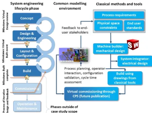
Figure 4 describes the use of the vueOne engineering toolset within the context of the case study. The project leader agreed to the use of the vueOne engineering toolset to support in the design and development of the MLP system provided that it did not hinder the engineering and build processes. Furthermore, it was agreed that the engineering tools would be used to virtually commission the MLP system using the digital twin created at the development phase. However, as demonstrated in Fig. 3, the case study demonstrates the workflow to the point of build only. The remaining phases of the lifecycle of the system within the project and how they are supported by the CPS enabled toolset are planned for future publication.
At the concept development phase of the project, certain constraints and requirements already existed. These included the end user’s standards regarding health and safety, risk assessment procedures, and machine design requirements that included aspects such as ergonomics and communication protocols. In conjunction with machine builders, system integrators, and engineers and researchers from the University, the end user set a concept scope. This provided sufficient information to the machine builders to begin designing various concepts from a mechanical perspective. They were
continuously reviewed and iterated upon until the designs were at a stage where more detailed process planning could occur. At this point in the design phase, the vueOne engineering toolset was employed. The ability to model human operators and their interaction with the machine, through the V-man
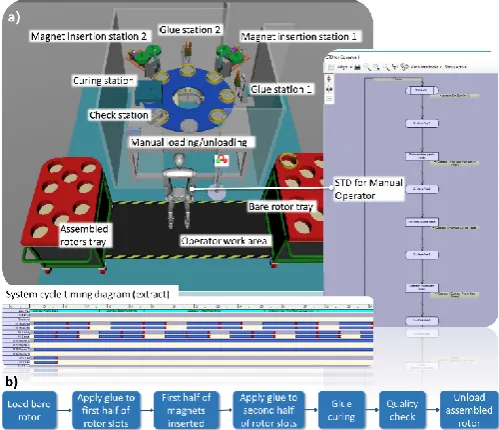
[image:5.595.63.271.66.145.2]module, provided valuable insight on the design from an ergonomics perspective. Visualisation through simulations within the vueOne engineering tools informed areas for improvement of the system design that were communicated to the end user and the machine builder at virtual design reviews. After a series of design reviews, the initial concept evolved into a digital prototype (Fig. 5a) and the process as described in Fig. 5b. This prototype utilised a rotary table that accommodated eight rotor laminations, two glue dispensers, two bespoke magnet insertion machines, and a single curing station. The station was loaded and unloaded by a human operator. This configuration was simulated and presented at a virtual build event, which was a significant milestone within the project. At this point of the project the respective component geometries, human-machine interaction, operator movement, process design, station layout, workpiece routing, and potential clash points were reviewed and validated. The feedback from the virtual build event was to modify the system and introduce robots to replace the magnet insertion machines and the glue dispensing systems. This was with a view to increasing the station flexibility should product design changes need to be introduced. Furthermore, it reduced costs due to the elimination of bespoke magnet insertion machines. The modified station layout can be seen in Fig. 6a and the new process in Fig. 6b. The process is described in detail in Fig. 6b than Fig. 5b due to the more mature design i.e. specifics concerning the interaction of the human and the machine were considered in greater detail. It is important to highlight that the model illustrated in Fig. 6a shows both the interaction between the human and the system and the collaboration between the robots. This design therefore made use of the V-Rob module and successfully modelled robot behavior and interaction with the wider system. The STD for the dispensing robot is presented in this figure to highlight the complexity of this interaction, as can be seen by the conditions highlighted in yellow. This is contrasted to the relatively simple conditions associated with the behavior of the operator in Fig. 5a. The
[image:5.595.302.549.68.252.2]cycle timing diagrams illustrated at the base of the both Fig. 5a and Fig 6a are generated automatically through the logic engine of the vueOne engineering tools by aggregating STDs for each component within the system. The cycle timing diagram illustrate good utilisation of resources in Fig. 4a as each station on the turntable is able to work on the workpiece. In contrast, the cycle timing diagram in Fig. 5a illustrates much poorer resource utilisation demonstrating a bottleneck incurred as consequence of using a lower cost robotic solutions, as this project is associated with realising an MLP facility. However higher volume demands for the real production system may justify the better productivity of the initial design and the higher investment costs could then be justified. Fig. 7 is a photo of the system during the build phase.
4.2.Evaluation
The vision proposed within the methodology section is that the vueOne engineering toolset supports the full lifecycle of the production system. However, within the context of the project it was found that the concept development phase saw limited value from the tools. This was due to the lack of a pre-existing generic component library. It is envisioned that the vueOne toolset will, in the future, have a database with components from previous projects. However, this may still not be sufficient to support system development at the early phases as typically many components are detailed, with bespoke geometries that may have not have been used in other projects. It may therefore be more beneficial to create classes of component types that have parametric geometries, which can be modified by the user depending on the need. These can be added to the concept phase models to rapidly begin the process of validating configurations and process planning based on end user requirements.
Currently the tool exports MODAPTS code in an XML file that contains information provided by the user and interpreted by the tool. A possible improvement is to create an option within vueOne that allows automatic ergonomics and metabolic analysis. This option will improve optimisation of
assembly operations and workload capabilities at the initial lifecycle stages. A prototype of this capability is already being developed, but is insufficiently mature to be deployed within industrial projects [26].
[image:6.595.40.290.68.283.2]Another possible vueOne toolset improvement is to exploit the component-based open data model within the software. Discussion with the end-user highlighted the need to add additional information about machines, such as rpm, temperature, power etc. This would allow the tool to provide warnings to the user about safety concerns in line with end-user or more general safety standards i.e. trip hazards for cables,
Figure 7 Status of machine in build phase at time of writing Figure 5 a) Configuration and layout of initial design with extract of cycle
timing diagram and example state transition diagram for operator behaviour, b) System process description
[image:6.595.312.575.68.384.2] [image:6.595.311.554.571.764.2]6 Author name / Procedia CIRP 00 (2017) 000–000
danger from hot surfaces etc. It could also be possible to constrain the movement of the V-Man based on the machine structure around it.
The machine builders were asked whether they could see the in-house use of the engineering tools within the mechanical design phase of the project. They felt that while the tools provided valuable information at later stages of the development phase, they could not see the value in the tools to support their own engineering activities. The lack of detail, to enable a lightweight model, meant that certain nuanced constraints could not be determined and rectified.
Despite these shortcomings, the tools were deemed to be fundamental in modeling, simulating, and evaluating the interaction of human operators, robots, and machines within the wider system. Although the engineering tools of the machine builder have the ability to accommodate kinematic behavior, the environments used support only manipulation and not logical control or integration. Furthermore, the engineering toolset of the end-user does not currently present an engineering workflow that imports models from machine builders to integrate them. The information gleaned from visualisations of operator-machine interactor were fundamental in ensuring that the machine met end-user safety and ergonomic requirements. Thus the engineering toolset can be seen as a valuable integration framework as illustrated in Figure 3.
5.Conclusions and Further Work
The main objective of this paper was to demonstrate the use of CPS enabled virtual engineering tools within a practical workflow to complement existing engineering tools and methods. Furthermore, it was important to the authors that this was demonstrated on a real industrial project rather than a lab based system where the risks, requirements, and stakeholder pressures are considerably reduced. The study has demonstrated the use of the vueOne toolset up to the build phase of a machine using a common model. The engineering tools have been fundamental in bringing together stakeholders and integrating various system elements. Future work will show how this model can be truly exploited throughout the lifecycle. Furthermore, the valuable feedback from the various stakeholders within the project will be taken on board to i) introduce the ability to carry out process planning at earlier phases through abstracted components, and ii) enrich the component data model with information about safety and other industrial requirements/standards. The true birth of a CPS occurs during the commissioning phase of the system. It is proposed that through the engineering workflow described in Fig. 3, the CPS vision can be realised, and that this paper builds the case for such an approach and is embraced by the industry.
Acknowledgements
The authors gratefully acknowledge the support of the Advanced Propulsion Centre for their funding of the HVEMS-UK project (ref: 102082). The authors gratefully acknowledge the contributions of D. Bolton (Horizon Instruments), S. Hilliard (Horizon Instruments), C. Sovrea (JLR), J. Barker (JLR), A. Jain (JLR), R. Kavade (WMG) and M. Patching (WMG). The support of the EPSRC via the KDCM project (ref:
EP/K018191/1) has also been essential to the refinement of the vueOne toolset and is fully acknowledged.
References
[1] (2016). Project homepage - High Volume E-Machine Supply from the UK (HVEMS-UK) Available: http://gtr.rcuk.ac.uk/projects?ref=102082 [2] H. Kagermann, J. Helbig, A. Hellinger, and W. Wahlster,
Recommendations for implementing the strategic initiative INDUSTRIE 4.0: Securing the future of German manufacturing industry; final report of the Industrie 4.0 Working Group. Forschungsunion, 2013.
[3] E. A. Lee, "Cyber physical systems: Design challenges," in 2008 11th IEEE International Symposium on Object and Component-Oriented Real-Time Distributed Computing (ISORC), 2008, pp. 363-369: IEEE. [4] R. Harrison, D. Vera, and B. Ahmad, "Engineering methods and tools for
cyber–physical automation systems," Proceedings of the IEEE, vol. 104, no. 5, pp. 973-985, 2016.
[5] "SolidWorks - 3D software tools," Dassault Systemes. [6] CAE software solutions. Available: http://www.eplan.co.uk/
[7] "Process Simulate: Manufacturing process verification in a powerful 3D environment," SIEMENS, 2012.
[8] "DELMIA V5 Automation Platform: Merging Digital Manufacturing with Automation," ARC Advisory Group, 2006.
[9] "A Desktop Engineering Guide: V6 Explained," dte (DeskTop Engineering), 2015.
[10] F. Demoly, O. Dutartre, X.-T. Yan, B. Eynard, D. Kiritsis, and S. Gomes, "Product relationships management enabler for concurrent engineering and product lifecycle management," Computers in Industry, vol. 64, no. 7, pp. 833-848, 2013.
[11] Analysis techniques for system reliability - Procedure for failure modes and effects analysis (FMEA), 2006.
[12] "Directive 2006/42/EC of the European Parliament and of the Council,"
Official Journal of the European Union, 2006.
[13] E. Westkämper and L. Jendoubi, "Smart factories–Manufacturing environments and systems of the future," in Proceedings of the 36th CIRP International Seminar on Manufacturing Systems, 2003, pp. 13-16. [14] Z. Liu, C. Diedrich, and N. Suchold, Virtual Commissioning of
Automated Systems. INTECH Open Access Publisher, 2012.
[15] X. Kong, B. Ahmad, R. Harrison, Y. Park, and L. J. Lee, "Direct deployment of component-based automation systems," in Proceedings of 2012 IEEE 17th International Conference on Emerging Technologies & Factory Automation (ETFA 2012), 2012, pp. 1-4: IEEE.
[16] M. Bergert and J. Kiefer, "Mechatronic data models in production engineering," IFAC Proceedings Volumes, vol. 43, no. 4, pp. 60-65, 2010. [17] P. Hoffmann, R. Schumann, T. M. Maksoud, and G. C. Premier, "Virtual Commissioning Of Manufacturing Systems A Review And New Approaches For Simplification," in ECMS, 2010, pp. 175-181. [18] L. Exel, G. Frey, G. Wolf, and M. Oppelt, "Re-use of existing simulation
models for DCS engineering via the Functional Mock-up Interface," in
Proceedings of the 2014 IEEE Emerging Technology and Factory Automation (ETFA), 2014, pp. 1-4: IEEE.
[19] A. Strahilov et al., "Improving the transition and modularity of the virtual commissioning workflow with AutomationML," in 4th AutomationML User Conference, Esslingen, Germany, 2016.
[20] R. Drath, A. Lüder, J. Peschke, and L. Hundt, "AutomationML-the glue for seamless automation engineering," in Emerging Technologies and Factory Automation, 2008. ETFA 2008. IEEE International Conference on, 2008, pp. 616-623: IEEE.
[21] A. Brusaferri, A. Ballarino, F. A. Cavadini, D. Manzocchi, and M. Mazzolini, "CPS-based hierarchical and self-similar automation architecture for the control and verification of reconfigurable manufacturing systems," in Proceedings of the 2014 IEEE Emerging Technology and Factory Automation (ETFA), 2014, pp. 1-8: IEEE. [22] S. Weyer and T. Meyer, "Open semantic meta-model as a cornerstone for
the design, engineering and management of CPS-based Factories," in 4th AutomationML User Conference, Esslingen, Germany, 2016.
[23] L. Wang, M. Törngren, and M. Onori, "Current status and advancement of cyber-physical systems in manufacturing," Journal of Manufacturing Systems, vol. 37, no. Part 2, pp. 517-527, 2015.
[24] L. Monostori et al., "Cyber-physical systems in manufacturing," CIRP Annals - Manufacturing Technology, vol. 65, no. 2, pp. 621-641, // 2016. [25] P. Carey, J. Farrell, M. Hui, and B. Sullivan, "Heyde’s MODAPTS: A
language of work," Heyde Dynamics Party ltd, pp. 27-94, 2001. [26] B. Alkan, D. Vera, M. Ahmad, B. Ahmad, and R. Harrison, "A
lightweight approach for human factor assessment in virtual assembly designs: an evaluation model for postural risk and metabolic workload,"