© 2019, IRJET | Impact Factor value: 7.211 | ISO 9001:2008 Certified Journal | Page 3108
Wearable Sensor Based Fall Detection System
Aneena George
1, Ashitha Haridas
2, Athira K P
3, Sreepriya E V
4, Prof. Sarin Abraham
51,2,3,4
Student, Dept. of Electronics and Communication Engineering, MACE, Kerala, India
5
Assisstant Professor, Dept. of Electronics and Communication Engineering, MACE, Kerala, India
---***---Abstract -
Fall detection is a major challenge in the publichealthcare domain, especially for the elderly as the decline of their physical fitness, and timely and reliable surveillance is necessary to mitigate the negative effects of falls. This project develops a novel fall detection system based on a wearable device. The system monitors the movements of human body, recognizes a fall from normal daily activities by an effective quaternion algorithm, and automatically sends request for help to the caregivers with the patients location.
1. INTRODUCTION
Falls of the elderly always lead to serious health issues as the decline of their physical fitness. Fracture is the most common injury in fall of an elderly situations, the fall process is the main source of injury because of the high impact. But sometimes the late medical salvage may worsen the situation. That means the faster the salvage comes, the less risk the elderly will face.
Progress of technology brings more possibilities to help us protect the elderly. Low power consumption components make it possible to realize wearable monitoring device. MEMS (micro electro-mechanical systems) sensors have simplified the design and implementation of sensor system. Location based service (LBS) makes it more convenient to locate the elderly in health monitoring. Beside these, mobile computing makes remote health monitoring easier to realize.
Several kinds of fall detection methods have been developed or applied in our life. One of them is computer vision based method. Cameras are distributed at limited space to offer pictures or videos of human activities to implement fall detection algorithm. External supports such as motion sensors could be used to enhance computer vision based fall detection method, and a data fusion algorithm can operate the validation and correlation among the two subsystems to raise robust performance of fall detection. These computer based methods work effectively in indoor environment, but they are hard to realize in outdoor environment as the deployment of cameras is always limited.
But, in fact, using more sensors means more power consumption, and it is a challenge to design a proper algorithm to fuse different kinds of sensors. A single triaxial accelerometer is quite enough for human fall detection as suffcient information could be extracted from its measurements. Besides this, the accelerometer coordinate
does not have to be fixed if only the magnitude of sum vector is needed, and that is quite convenient for wearable application. In this paper, a fall detection system based on a wearable device is developed. The hardware and software realization of the device is mainly based on a single triaxial accelerometer and GPS/GSM module. The device uses an efficient fall detection algorithm with less resource and power consumption, which means that it is a proper design for outdoor application
.
2. LITERATURE SURVEY
The rapid aging of the world's population, along with an increase in the prevalence of chronic illnesses and obesity, requires adaption and modification of current healthcare models. One such approach involves telehealth applications, many of which are based on sensor technologies for unobtrusive monitoring. Recent technological advances, in particular, involving micro electro-mechanical systems, have resulted in miniaturized wearable devices that can be used for a range of applications. One of the leading areas for utilization of body-fixed sensors is the monitoring of human movement. An overview of common ambulatory sensors is presented, followed by a summary of the developments in this field, with an emphasis on the clinical applications of falls detection, falls risk assessment, and energy expenditure. The importance of these applications is considerable in light of the global demographic trends and the resultant rise in the occurrence of injurious falls and the decrease of physical activity. The potential of using such monitors in an unsupervised manner for community-dwelling individuals is immense, but entails an array of challenges with regards to design considerations, implementation protocols, and signal analysis processes.
3. DESIGN
In this a microcontroller is employed to handle data transfer operations. We are using PIC microcontroller (PIC16F877A), which are a family specialised microcon-troller chips produced by microchip technology. The acronym PIC stands for peripheral interface controller. A microcontroller is compact microcomputer designed to govern the operation of three axis accelerometer and GSM/GPS module etc.
© 2019, IRJET | Impact Factor value: 7.211 | ISO 9001:2008 Certified Journal | Page 3109 where a person falls. The GSM module is used to transmit the
message when a person falls. The decision making for sending message and location is based on the data received from the tri-axial accelerometer. The power unit supplies +5V to the microcontroller, GSM and GPS module for its working
.
[image:2.595.51.278.215.367.2]3.1Block Diagram
Fig -1: Block Diagram
The PIC microcontroller have +5V power supply. The PIC microcontroller always check the changes in accelerometer. The three axis of accelerometer is connected to the three analog pins of PIC microcontroller. When a person falls, the controller checks the changes in axis of accelerometer and if it goes above a threshold value(set as 300V), microcontroller receives the location from GPS and transmits to GSM module, which sends the message to the caregiver. The receiver pin of PIC is connected to the transmit pin of GPS module. The transmitter pin of PIC is connected to the receiver pin of GSM module. Both GSM and GPS are interfaced with PIC microcontroller through transmitter and receiver pins. Then the system detects falling.
3. COMPONENTS
3.1 PIC Microcontroller
[image:2.595.333.539.512.623.2]The PIC microcontroller PIC16F877A is one of the most renowned microcontrollers in the industry. This microcontroller is very convenient to use, the coding or programming of this controller is also easier. One of the main advantages is that it can be write-erase as many times as possible because it use FLASH memory technology. It has a total number of 40 pins and there are 33 pins for input and output. There are 40 pins of this microcontroller IC. It consists of two 8 bit and one 16 bit timer. Capture and compare modules, serial ports, parallel ports and _ve input/output ports are also present in it
.
Fig -2 PIC16F877A
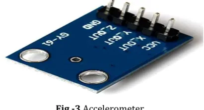
3.2 Accelerometer
The ADXL345 is a small, thin, low power, three-axis MEMS accelerometer with high resolution (13-bit) measurement up to 16g. Digital output data is formatted as 16-bit twos complement and is accessible through either a SPI (3- or 4-wire) or I2C digital interface.
The ADXL345 is well suited for mobile device applications. It measures the static acceleration of gravity in tilt-sensing applications, as well as dynamic acceleration resulting from motion or shock. Its high resolution (4mg/LSB) enables resolution of inclination changes of as little as 0.25.
Several special sensing functions are provided. Activity and inactivity sensing detect the presence or lack of motion and if the acceleration on any axis exceeds a user-set level. Tap sensing detects single and double taps. Free-Fall sensing detects if the device is falling. These functions can be mapped to interrupt output pins. An integrated 32 level FIFO can be used to store data to minimize host processor intervention. Low power modes enable intelligent motion-based power management with threshold sensing and active acceleration measurement at extremely low power dissipation.
Fig -3 Accelerometer
3.3 GSM Module
© 2019, IRJET | Impact Factor value: 7.211 | ISO 9001:2008 Certified Journal | Page 3110 communications, _rst by circuit-switched transport, then by
[image:3.595.323.546.196.286.2]packet data transport via General Packet Radio Service (GPRS), and Enhanced Data Rates for GSM Evolution (EDGE).Subsequently, the 3GPP developed third generation (3G) UMTS standards, followed by fourth-generation (4G) LTE Advanced standards, which do not form part of the ETSI GSM standard."GSM" is a trademark owned by the GSM Association. It may also refer to the (initially) most common voice codec used, Full Rate.
Fig -4 GSM Module
3.4 GPS Module
GPS receivers are generally used in smart phones, fleet management system, military etc. for tracking or finding location.
Global Positioning System (GPS) is a satellite-based system that uses satellites and ground stations to measure and compute its position on Earth.GPS is also known as Navigation System with Time and Ranging (NAVSTAR) GPS. GPS receiver needs to receive data from at least 4 satellites for accuracy purpose. GPS receiver does not transmit any information to the satellites.GPS receiver uses a constellation of satellites and ground stations to calculate accurate location wherever it is located. These GPS satellites transmit information signal over radio frequency (1.1 to 1.5 GHz) to the receiver. With the help of this received information, a ground station or GPS module can compute its position and time.
GPS receiver receives information signals from GPS satellites and calculates its distance from satellites. This is done by measuring the time required for the signal to travel from satellite to the receiver.
Fig -5 GPS Module
3.5 DBDB101G Rectifier
These are the equipment that converts the alternating current into direct current. The process of conversion from ac (alternating current) to dc (direct current) is known as rectication. These are very important circuits in the designing the dc power supply.
Fig -6 DBDB101G Rectifier
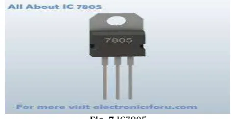
3.6 IC7805
IC 7805 is a 5V Voltage Regulator that restricts the output voltage to 5V output for various ranges of input voltage. It acts as an excellent component against input voltage fluctuations for circuits, and adds an additional safety to your circuitry. It is inexpensive, easily available and very much commonly used. With few capacitors and this IC you can build pretty solid and reliable voltage regulator in no time. A Circuit diagram with pinout is given. It also comes with provision to add heat sink.
[image:3.595.56.263.213.334.2]The maximum value for input to the voltage regulator is 35V. It can provide a constant steady voltage of 5V for higher voltage input till the threshold limit of 35V. If the input voltage is near to 7.2V to 12V then it does not produce any heat and hence no need of heat sink. Higher the input volts - the more it gets heated up and excess electricity is liberated as heat from 7805. Hence the provision of heat sink. IC7805 also comes as smaller SMD component as well.
Fig -7 IC7805
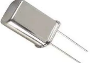
3.7 Crystal Oscillator
[image:3.595.313.549.551.673.2]© 2019, IRJET | Impact Factor value: 7.211 | ISO 9001:2008 Certified Journal | Page 3111 signal for digital integrated circuits, and to stabilize
frequencies for radio transmitters and receivers. The most common type of piezoelectric resonator used is the quartz crystal, so oscillator circuits incorporating them became known as crystal oscillators, but other piezoelectric materials including polycrystalline ceramics are used in similar circuits.
[image:4.595.83.234.310.415.2]A crystal oscillator, particularly one using a quartz crystal, works by distorting the crystal with an electric _eld, when voltage is applied to an electrode near or on the crystal. This property is known as electrostriction or inverse piezoelectricity. When the field is removed, the quartz- which oscillates in a precise frequency - generates an electric field as it returns to its previous shape, and this can generate a voltage. The result is that a quartz crystal behaves like an RLC circuit, but with a much higher Q.
Fig -8 Crystal Oscillator
4. SOFTWARE
4.1 Eagle
EAGLE is a scriptable electronic design automation (EDA) application with schematic capture, printed circuit board (PCB) layout, auto-router and computer-aided manufacturing (CAM) features. EAGLE contains a schematic editor, for designing circuit diagrams. Schematics are stored in files with .SCH extension; parts are defined in device libraries with .LBR extension. Parts can be placed on many sheets and connected together through ports. The PCB layout editor stores board files with the extension .BRD. It allows back-annotation to the schematic and auto-routing to automatically connect traces based on the connections defined in the schematic. EAGLE saves Gerber and PostScript layout files as well as Excellon and Sieb and Meyer drill files. These are standard file formats accepted by PCB fabrication companies, but given EAGLE's typical user base of small design firms and hobbyists, many PCB fabricators and assembly shops also accept EAGLE board files (with extension .BRD) directly to export editing, project management and to customize the interface and design parameters. The system can optimized production files and pick-and-place data themselves. EAGLE provides a multi-window graphical user interface and menu system for be controlled via mouse, keyboard hotkeys or by entering specific commands at an embedded command line. Multiple
repeating commands can be combined into script files (with _le extension .SCR). It is also possible to explore design files utilizing an
EAGLE-specifi
c object-oriented programming language (with extension .ULP)4.2 MikroC
The mikroC PRO for PIC is a powerful, feature-rich development tool for PIC microcontrollers. It is designed to provide the programmer with the easiest possible solution to developing applications for embedded systems, without compromising performance or control.PIC and C _t together well: PIC is the most popular 8-bit chip in the world, used in a wide variety of applications, and C, prized for its e_ciency, is the natural choice for developing embedded systems. mikroC PRO for PIC provides a successful match featuring highly advanced IDE, ANSI compliant compiler, broad set of hardware libraries, comprehensive documentation, and plenty of ready-to-run examples.
4.2.1 Process of MikroC
1. Write your C source code using the built-in Code Editor (Code and Parameter Assistants, Code Folding, Syntax Highlighting, Auto Correct, Code Templates, and more.) 2. Use included mikroC PRO for PIC libraries to dramatically speed up the development: data acquisition, memory, displays, conversions, communication etc.
3. Monitor your program structure, variables, and functions in the Code Explorer.
4. Generate commented, human-readable assembly, and standard HEX compatible with all programmers.
5. Use the integrated mikroICD (In-Circuit Debugger) Real Time debugging tool to monitor program execution on the hardware level.
6. Inspect program and debug executable logic with the integrated Software Simulator.
7. Generate COFF(Common Object File Format) _le for software and hardware debugging under Microchip's MPLAB software.
8. Active Comments enable you to make your comments alive and interactive.
9. Get detailed reports and graphs: RAM and ROM map, code statistics, assembly listing, calling tree, and more.
10. mikroC PRO for PIC provides plenty of examples to expand, develop, and use as building bricks in your projects. Copy them entirely if you deem fit that’s why we included them with the compiler.
5. HARDWARE IMPLEMENTATION AND RESULTS
5.1 PCB Schematic and Layout
5.1.1 Design steps of PCB
© 2019, IRJET | Impact Factor value: 7.211 | ISO 9001:2008 Certified Journal | Page 3112 schematic. To add a component you need to click the add
button. Then _nd your component. Click OK and you should have the schematic sign of your component, just click and it will be added. That I show you add a part. Keep doing that Intel you have all the parts you need. To turn a component all you have to do is right click.
2. Connecting Components.
To connect your components you have to click the wire button. Then click on one part you want to connect then click the other. If you right click then the angle that the lin tirns at and direction will change.
3. Converting Schematics to Board
To convert your schematic to a board all you have to do is press the board button. Ones you clicked that a window should pop up and you should see your components outside of the square to move your components click the move button. The yellow lines that you see connecting your components means that they are unrouted. There are 2 ways to rout your component. One way is by hand and the other way is using the auto route button. To rout by hand you click the rout button then click the two ends of the components. When the line that you make is red then its on the top of the board if the line is blue than it is on the bottom to use auto route just click auto.
4. Other Things
You can also add text in your board all you have to do is click the button that seas text, type what you want it to say then click ok. Your text might come up in red or blue this Is not good but it is ease to fix. All you have to do Is click select layer button then find ether Tsilk or Bsilk. Tsilk means that your text will be on the silk layer on the top of the board. Bsilk means that your text will be on the bottom of the board. Then click where you want your text to be just make sure that it is not over any holes, or pads.
5. Finished
[image:5.595.310.561.100.257.2]PCB schematic and PCB layout are designed.
[image:5.595.309.558.432.621.2]Fig -9 PCB Schematic
Fig -10 PCB Layout
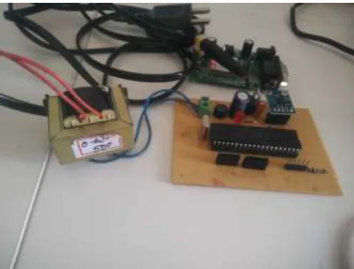
6. PROTOTYPE
The final prototype model shown in figure 4.2. We have made a fall detection system using PIC microcontroller, accelerometer, GSM and GPS module. For power supply we use a transformer of +12V. The GPS locate the place and GSM send the message. Accelerometer changes its three axis when a person falls. DBDB101G rectifier, capacitors and IC7805 are used to convert AC to DC and also to convert +12V to +5V. The location is send as longitude and lattitude. The message is shown as "FALL". The system is tested in outdoor.
Fig -11 Prototype of fall detection system
7. CONCLUSIONS
7.1 Advantages
1. The fall detection system is using single triaxial accelerometer, to reduce power consumption.
© 2019, IRJET | Impact Factor value: 7.211 | ISO 9001:2008 Certified Journal | Page 3113
7.2 Disadvantages
1. The system detects fall, but cannot distinguish different activities.
2. The size of the wearable system is large which made difficult to the person to carry it.
8. FUTURE SCOPE
Since this fall detection system is built as a prototype it has various limitations. More research should do to improve the current proposed system. Sufficient sample number collected from subjects with different age and gender will improve the reliability and robustness of the threshold
.
REFERENCES
[1] M. K. Karlsson, H. Magnusson, T. von Schewelov, and B. E. Rosengren, Prevention of falls in the elderlya review, Osteoporosis International, vol. 24, no. 3, pp. 747762, 2013. [2] T. Shany, S. J. Redmond, M. R. Narayanan, and N. H. Lovell, Sensors-based wearable systems for monitoring of human movement and falls, IEEE Sensors Journal, vol. 12, no. 3, pp. 658670, 2012.
[3] M. Grassi, A. Lombardi, G. Rescio et al., An integrated system for people fall-detection with data fusion capabilities based on 3D ToF camera and wireless accelerometer, in Proceedings of the 9th IEEE Sensors Conference (SENSORS '10), pp. 10161019, Kona, Hawaii, USA, November 2010. [4] . Abbate, M. Avvenuti, G. Cola et al., Recognition of false alarms in fall detection systems, in Consumer Communications and Networking Conference (CCNC '11), pp. 2328, Las Vegas, Nev, USA, 2011.