ABSTRACT
CAI, SHAOBO. Novel Polymer Composite Materials and Stimulation Devices for Bone Tissue Engineering Applications. (Under the direction of Dr. Thom LaBean).
Tissue engineering is a promising therapeutic approach to treat large tissue defects, addressing the challenges of limited tissue sources or potential host rejection in traditional treatment methods such as autograft and allograft. To obtain engineered tissues with ideal physiological conditions, two components are crucial for the tissue regeneration process: scaffold materials and biomimetic stimuli. Each of these components and their interactions have a significant impact on the functionality of engineered tissues.
In this dissertation, from a materials science and engineering aspect, advances in the development of functional scaffold materials and novel stimulation devices were performed. Relevant mechanisms of the interactions between the developed materials, or devices, with biological responses were also systematically studied.
synergistic antibacterial effect at the material interface was found on the fabricated polymer composite, where the material exhibited significantly lower affinity to bacterial adhesion. In the second part of this dissertation, a novel electrical field stimulation device was developed. The micro-fabricated stimulation device consists of micro-sized interdigitated electrodes, which provide a stable and consistent electric field above the surface. This configuration ensures the generation of a physiologically relevant electric field, even with application of ultra-low electric voltages, eliminating potential adverse electrochemical effects. Polymers were also coated onto the surface of the electrodes to further improve the biocompatibility of the stimulation device.
Novel Polymer Composite Materials and Stimulation Devices for Bone Tissue Engineering Applications
by Shaobo Cai
A dissertation submitted to the Graduate Faculty of North Carolina State University
in partial fulfillment of the requirements for the degree of
Doctor of Philosophy
Materials Science and Engineering
Raleigh, North Carolina 2018
APPROVED BY:
_______________________________ _______________________________
Dr. Thomas LaBean Dr. Elizabeth Loboa-Polefka
Committee Chair
_______________________________ _______________________________
ii DEDICATION
iii BIOGRAPHY
Shaobo Cai was born on Dec 22nd, 1988 in Suzhou, Anhui, China. After graduated from Suzhou
iv ACKNOWLEDGMENTS
I would like to thank all my committee members for all the valuable advice and time to evaluate my work. In particular, I am sincerely grateful to my academic advisor Dr. Elizabeth Loboa for her great mentorship and thoughtful insights during my Ph.D. Without the encouragement and guidance from her, this work would not have been possible. I’m also grateful to Dr. Behnam Pourdeyhimi for his guidance and advice, especially for the research related to nonwovens. I would like to thank Dr. Matt Fisher and Dr. Thom LaBean for all the support and help regarding my research and Ph.D. progress. I also would like to thank Dr. Maurice Balik for all the useful knowledge about polymers he taught me in all his classes I have taken.
I’m also thankful to my industrial advisors, Chris Creagan, Andrew Goodby, Robert Green, Perry Potnis, Karthik Ramaratnam and Kris Senecal for their advice and feedback about my research. Additionally, I would like to thank the funding sources for my Ph.D. study and research, including the National Science Foundation, and the Nonwovens Institute and its member companies.
v graduate students from the Nonwovens Institute, especially William Barnes, Jimei Wang, Amy Minton, Anglo Corino and Sharon Wright.
vi TABLE OF CONTENTS
LIST OF TABLES ... x
LIST OF FIGURES ... xi
1. CHAPTER I: Introduction ... 1
2. CHAPTER II: Industrial-Scale Fabrication of Osteogenic Polymer Composites for Tissue Engineering Applications ... 5
Motivation ... 5
2.1. CHAPTER II PART 1: Industrial-Scale Fabrication of Stacked PLA/TCP Composite Meshes as Constructs for Tissue Regeneration ... 6
2.1.1. Introduction: ... 6
2.1.2. Materials and Methods:... 8
2.1.2.1. Fabrication of composite meshes. ... 8
2.1.2.2. Fabrication of stacked composite meshes. ... 9
2.1.2.3. Fabrication of 3D printed scaffolds. ... 10
2.1.2.4. Fabrication of electrospun scaffolds. ... 10
2.1.2.5. Human stem cells isolation and culture. ... 11
2.1.2.6. Cell viability and calcium accretion. ... 11
2.1.2.7. Immunostaining. ... 12
2.1.2.8. Statistical analyses. ... 12
2.1.3. Results and Discussion ... 13
2.1.3.1. Composite morphology. ... 13
2.1.3.2. Cell seeding efficiency. ... 15
2.1.3.3. Cell proliferation... 17
2.1.3.4. Cell viability analyses. ... 19
2.1.3.5. Osteogenic differentiation evaluation. ... 20
2.1.4. Conclusion: ... 21
2.2. CHAPTER II PART 2: Industrial-Scale Fabrication of Osteogenic and Antibacterial PLA/Silver-Loaded Calcium Phosphate Composite Meshes with Significantly Reduced Cytotoxicity ... 23
2.2.1. Introduction: ... 23
2.2.2. Materials and Methods:... 24
2.2.2.1. Synthesis of the calcium phosphates. ... 24
vii
2.2.2.3. Material characterizations. ... 27
2.2.2.4. Antibacterial analyses. ... 27
2.2.2.5. Human stem cells isolation and culture. ... 28
2.2.2.6. Cell viability and calcium accretion. ... 29
2.2.2.7. Silver release profiles. ... 30
2.2.2.8. RNA extraction and gene expression analyses. ... 30
2.2.2.9. Statistical analyses. ... 31
2.2.3. Results and Discussion ... 31
2.2.3.1. Characterization of synthesized additives. ... 31
2.2.3.2. Antibacterial analyses. ... 33
2.2.3.3. Cytotoxicity tests. ... 35
2.2.3.4. Mechanism studies. ... 37
2.2.3.5. Osteogenic differentiation. ... 40
2.2.4. Conclusion. ... 44
3. CHAPTER III A High Throughput Fabrication Method of Silver Nanoparticles-Doped-Nanoclay Polymer Composite with Synergistic Antibacterial Effect at the Interface... 45
Motivation ... 45
3.1.1. Introduction: ... 46
3.1.2. Materials and Experiments: ... 48
3.1.2.1. Materials. ... 48
3.1.2.2. Silver NP-nanoclay production. ... 48
3.1.2.3. Composite fabrication... 48
3.1.2.4. Composite characterizations. ... 49
3.1.2.5. Antibacterial tests. ... 50
3.1.2.6. Human skin cell viability test. ... 51
3.1.2.7. Data analyses. ... 52
3.1.3. Results and Discussion: ... 52
3.1.3.1. Composite fabrication... 52
3.1.3.2. Composite characterizations. ... 54
3.1.3.3. Bacterial-adhesion test. ... 58
3.1.3.4. Mechanism explanations. ... 60
viii
3.1.3.6. Cytotoxicity assessment. ... 69
3.1.3.7. Proposed future studies. ... 70
3.1.4. Conclusion. ... 72
4. CHAPTER IV: Structure‐Process‐Property Relationship Study of Additives Loaded Polymer Spun-Blown® Composites ... 73
Motivation ... 73
4.1.1. Introduction: ... 74
4.1.2. Background: ... 76
4.1.2.1. The SpunBlown® process. ... 76
4.1.2.2. Additives for meltblown. ... 78
4.1.2.3. Nanoclay additives. ... 79
4.1.3. Materials and Experiments: ... 80
4.1.3.1. Materials. ... 80
4.1.3.2. Rheological properties. ... 81
4.1.3.3. Crystallization behavior. ... 82
4.1.3.4. Fabrication of the composite meshes. ... 82
4.1.3.5. Scanning electron microscopy. ... 83
4.1.3.6. Transmission electron microscopy. ... 84
4.1.3.7. Mechanical properties. ... 84
4.1.4. Results and Discussion: ... 84
4.1.4.1. Nanoclay additives distribution. ... 84
4.1.4.2. Polymer crystallization behavior. ... 87
4.1.4.3. Rheological properties. ... 89
4.1.4.4. Composite mesh morphology. ... 90
4.1.4.5. Mechanical properties. ... 91
4.1.4.6. Pore size distribution. ... 94
4.1.4.7. Fiber diameter distribution. ... 94
4.1.5. Conclusion. ... 96
5. CHAPTER V: Development of an Novel Electrical Stimulation Device for Stem Cell Osteogenic Activation ... 97
Motivation ... 97
5.1.1. Introduction: ... 98
ix
5.1.2.1. Interdigitated electrode fabrication. ... 100
5.1.2.2. Cell isolation and culture. ... 102
5.1.2.3. Electric field stimulations. ... 103
5.1.2.4. Cell viability and calcium accretion. ... 103
5.1.2.5. RNA extraction and gene expression analyses. ... 104
5.1.2.6. Immunostaining. ... 104
5.1.2.7. siRNA knockdown. ... 105
5.1.2.8. Calcium imaging... 106
5.1.2.9. Data analyses. ... 106
5.1.3. Results and Discussion: ... 107
5.1.3.1. Osteogenesis of hASC. ... 107
5.1.3.2. Osteogenic markers and cilia structural proteins. ... 110
5.1.3.3. Primary cilia for EFS. ... 112
5.1.3.4. Ca2+ influx. ... 118
5.1.3.5. Stretch Ca2+ channels. ... 119
5.1.3.6. IDEs modifications. ... 126
5.1.3.7. Potential cytotoxicity. ... 128
5.1.3.8. Proposed future study. ... 131
5.1.4. Conclusion: ... 133
6. CHAPTER VI: Conclusions ... 134
6.1.1. Conclusion: ... 134
6.1.2. Recommendations for Future Work... 135
x LIST OF TABLES
Table 2. 1 Sample abbreviations and corresponding content of additives. ... 27
Table 3. 1 Optimized key fabrication parameters. ... 49
Table 3. 2 Sample abbreviations and correspondent additives loading content... 53
Table 3. 3 Bacterial adhesion tests. ... 59
Table 3. 4 Antibacterial test at the material interface. ... 65
Table 4. 1 Comparison of the process between SpunBlown® and meltblown. ... 76
Table 4. 2 Comparison of fabricated meshes by SpunBlown or meltblown. ... 77
xi LIST OF FIGURES
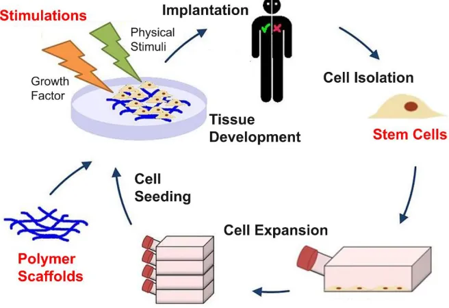
Figure 1. 1 General tissue engineering approach and critical components in the
process. 3 ... 1 Figure 2. 1 Stacked PLA/ TCP composite meshes as scaffold materials for
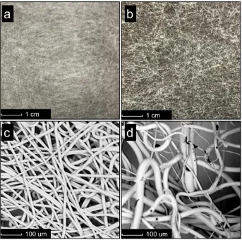
osteochondral tissue engineered constructs. ... 9 Figure 2. 2 Digital camera photos (a, b) and scanning electron microscopy (SEM)
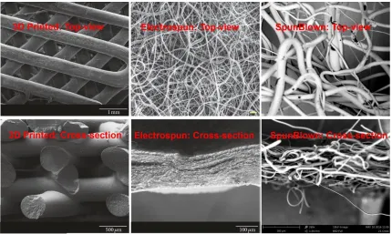
images (c, d) of fabricated PLA samples (a, c) and calcium phosphate loaded samples (b, d). ... 14 Figure 2. 3 Comparison of 3D printed, electrospun and Spunblown fabricated
materials by scanning electron microscopy (SEM). 73 ... 15 Figure 2. 4 Seeding efficiency of human adipose-derived stem cells cultured on
3D printed, electrospun and SpunBlown scaffolds observed by Live/Dead staining, after 4 hours of culture. Live cells = green; dead
cells = red. ... 16 Figure 2. 5 The spreading and proliferation of human adipose-derived stem cells
on 3D printed, electrospun and SpunBlown composite meshes. Cells were cultured for 3 weeks, fixed, and stained (actin = red; nuclei =
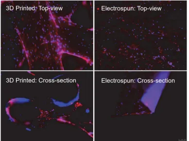
blue). ... 18 Figure 2. 6 Comparison of the top-view and cross-section view for human
adipose-derived stem cells cultured on 3D printed and electrospun scaffolds. Cells were cultured for 21 days in scaffolds, fixed, and
stained (actin = red; nuclei = blue). 73 ... 19 Figure 2. 7 Viability of human adipose-derived stem cells cultured on pure PLA
and 10 wt.% TCP loaded PLA SpunBlown composite meshes observed by Live/Dead staining, after 7 days and 14 days of culture.
Live cells = green; dead cells = red. ... 20 Figure 2. 8 hASC calcium accretion on SpunBlown and 3D printed PLA/TCP
scaffolds, after 14 days of culture. The extent of hASC calcium
accretion visualized by Alizarin Red (labeled in red). ... 21 Figure 2. 9 Fabrication process of the composite meshes. Additives were
synthesized by a solution co-precipitation method and compounded into the polymer. During the melt-blown process, polymer melts were attenuated by hot air streams. ... 26 Figure 2. 10 Energy dispersive X-ray spectroscopy (EDX) spectra of
as-precipitated additive powders a) CaP, b) silver-CaP. ... 32 Figure 2. 11 AATCC 100 testing results showing bacterial number reduction on
xii control, and silver-CaP loaded samples. Different letters indicate a
significant difference between the sample groups (p < 0.05). ... 34 Figure 2. 12 Representative photographs of incubated Staph. aureus diluted with a)
PLA negative control, b) silver NP + CaP, c) silver-CaP loaded
samples. ... 34 Figure 2. 13 AlamarBlue reductions of human adipose-derived stem cells (hASC)
seeded samples after 10 days of culture. A greater reduction % indicates higher cell viability or proliferation rate. Different letters
indicate a significant difference between the samples (p < 0.05). ... 36 Figure 2. 14 Viability of human adipose-derived stem cells observed by Live/Dead
staining, on PLA negative control, silver NP + CaP positive control and silver-CaP samples after 10 days of culture. Live cells = green;
dead cells = red. ... 37 Figure 2. 15 Release profiles of silver ions from the composite meshes loaded with
silver nanoparticles + CaP and silver-CaP. The concentrations of silver ions were evaluated at time points of 4-h, 36-h, 72-h, 120-h, 168-h, 216-h or 264-h. A steadier silver-ion release profile was
observed for silver-CaP loaded samples. ... 39 Figure 2. 16 Schematic of the proposed mechanism contributing to the differential
cytotoxicity found in the silver-CaP loaded composite and silver
nanoparticles directly loaded samples. ... 40 Figure 2. 17 hASC calcium accretion after 14 days of culture on a) PLA negative
control, b) silver nanoparticles + CaP samples, c) silver-CaP loaded composite. The degree of hASC mineralization was determined by
Alizarin Red (labeled in red). ... 41 Figure 2. 18 Quantified calcium accretion normalized to BCA protein content.
Different letters indicate there is a significant difference between the
samples (p < 0.05). ... 42 Figure 2. 19 mRNA expression in of osteogenic markers (a) Runx2 and (b) BMP2.
The mRNA expression normalized to the negative control PLA
samples (p < 0.05). ... 43 Figure 3. 1 Fabrication process of the nanocomposite and the in-situ thermal
reduction of silver nanoparticles on nanoclay. ... 54 Figure 3. 2 Scanning electron microscope (SEM) with back-scattered electron
detector images of a) silver NP samples and b) silver NP-nanoclay composite. Heavy metals show as bright spots (labeled with white
xiii Figure 3. 3 Energy-dispersive x-ray spectroscopy (EDX) spectra of a) pure PLA,
b) silver NP, c) nanoclay and d) silver NP-nanoclay doped sample. Spectra labeled in black boxes in c) and d) were enlarged as c’) and d’) to show the detail information, respectively. Representative results of localized EDX analysis (from areas labeled with the red boxes) of
e) silver NP and f) silver NP-nanoclay loaded samples. ... 56 Figure 3. 4 Transmission electron microscopy (TEM) micrograph of a) silver NP,
b) nanoclay and c) silver NP-nanoclay loaded samples. The silver nanoparticles are labeled with red arrows, and the dark lines represent the intersection of silicate layers. The white background corresponds to the PLA matrix. ... 58 Figure 3. 5 Fluorescent microscopy of the attached bacteria on a) pure PLA, b)
silver NP, c) nanoclay, and d) silver NP-nanoclay loaded samples. The Staphylococcus aureus bacteria were stained with SYTO® 9 dye, which shows as bright green punctate dots under fluorescent
microscopy. The faded green lines in the background are PLA fibers
that exhibit some auto-fluorescence. ... 60 Figure 3. 6 Atomic force microscopy (AFM) images of a) pure PLA b) silver NP
and c) nanoclay loaded PLA samples. Scale bars = 1 um. Note the difference in surface bump height, size and shape between nanoclay loaded samples with pure PLA samples. d) RMS roughness of the samples. Results demonstrate significantly greater surface roughness at sub-micron scale for nanoclay loaded sample. ‘*’ indicated a
significant difference between the two sample groups (p < 0.05). ... 62 Figure 3. 7 X-Ray diffraction (XRD) profiles of the samples. ... 63 Figure 3. 8 Possible mechanisms of reduced bacterial adhesion. The nano rough
surface on nanoclay or silver NP-nanoclay loaded samples prevents the bacteria from laying flush against the material surface, therefore
potentially reducing physical interactions. ... 64 Figure 3. 9 Representative photographs of incubated Staphylococcus aureus
detached and diluted from a) pure PLA, b) silver NP, c) nanoclay and d) silver NP-nanoclay loaded PLA samples. ... 66 Figure 3. 10 Schematic of proposed synergistic antibacterial effect at the material
interface. The nano rough surface of the silver NP-nanoclay composite significantly reduced the number of adherent bacteria
while the low-concentration silver ions released. ... 68 Figure 3. 11 Viability of human dermal fibroblasts on a) pure PLA, b) silver NP, c)
nanoclay and d) silver NP-nanoclay loaded PLA samples after 2
xiv Figure 3. 12 AlamarBlue reductions of human dermal fibroblasts seeded samples
after 1 and 2 weeks of culture. No significant statistical difference
was found between the different sample groups (p < 0.05). ... 70 Figure 3. 13 The nano- or submicron- structures at a material surface impact
cell/material recognition. The interface selective adsorb specific proteins from tissue fluids onto the structured surface. Cells recognize the material through adsorbed proteins on surface. 135 ... 71 Figure 4. 1 Schematic of the Biax die in the SpunBlown® system. Orifice is
surrounded by a co-concentric air stream providing fiber attenuation
for each filament.138-139 ... 74
Figure 4. 2 Schematic of stacked silicate platelets structure in nanoclay. 154 ... 79 Figure 4. 3 Three different types of dispersion for layered silicates loaded in
polymer.155 ... 80 Figure 4. 4 Cloisite® and Nanomer® nanoclays are montmorillonite layered
silicates modified with different surfactants. ... 81 Figure 4. 5 Transmission electron microscopy (TEM) images of the Cloisite®
nanoclay distribution in PLA matrix at concentration of 2.5 wt.% to
25 wt.%. ... 85 Figure 4. 6 Transmission electron microscopy (TEM) images of the Nanomer®
nanoclay distribution in PLA matrix at a concentration of 1 wt.%. ... 86 Figure 4. 7 Scanning electron microscopy (SEM) images of the fiber surface
morphology of PLA composite meshes loaded with different
concentration of nanoclay. ... 87 Figure 4. 8 The impact of loading nanoclay on PLA’s crystallization behavior
was evaluated by differential scanning calorimetry (DSC)... 88 Figure 4. 9 Shear viscosity profiles of nanoclay loaded PLA were analyzed by
both rotational and capillary rheometers. ... 89 Figure 4. 10 Scanning electron microscopy (SEM) of Cloisite® and Nanomer®
nanoclay loaded SpunBlown PLA composite meshes fabricated at air pressure 8 Psi. ... 90 Figure 4. 11 Scanning electron microscopy (SEM) of Cloisite® and Nanomer®
nanoclay loaded SpunBlown PLA composite meshes fabricated at air pressure 12 Psi. ... 91 Figure 4. 12 Tensile modulus of the Cloisite® nanoclay loaded polymer
composites. ... 92 Figure 4. 13 Tensile modulus of the Nanomer® nanoclay loaded polymer
xv Figure 4. 14 Scanning electron microscopy (SEM) images showing fiber
cross-sections of nanoclay loaded PLA composites. These images help show the compatibility issues between the nanoclays and PLA matrix, in particular with Cloisite® nanoclay. ... 93 Figure 4. 15 Pore size distribution of fabricated composite meshes loaded with
different percentage of Nanomer® nanoclays. ... 94 Figure 4. 16 Fiber diameter distribution for Cloisite® nanoclay loaded polymer
composites meshes at lower air pressure (8 psi). ... 95 Figure 4. 17 Fiber diameter distribution for Cloisite® nanoclay loaded polymer
composites meshes at higher air pressure (12 psi). ... 95 Figure 4. 18 Fiber diameter distribution for Nanomer® nanoclay loaded
composites meshes at higher air pressure (12 psi). ... 96 Figure 5. 1 The interdigitated electrode and simulated electrical filed in
COMSOL. The bright (white) regions are glass, whereas the dark regions are metal pads and electrode array. The simulation reveals that IDEs provided a stable and consistent electric field both parallel
to and above the surface of the electrode up to a height of 100 µm... 107 Figure 5. 2 hASC viability after up to 14 days of electrical field stimulation.
hASC exhibited high viability after up to 14 days exposure to 1 V/cm electric fields at 1 Hz for 4 hours per day. Observed by Live/Dead staining after electrical stimulation at respective time points. Live
cells = green; dead cells = red. ... 108 Figure 5. 3 hASC calcium accretion after up to 14 days of electrical field
stimulation. hASC were cultured in ODM and exposed to 1 V/cm electric field at 1Hz for 4 h/day. The degree of hASC mineralization
was determined by Alizarin Red staining. ... 109 Figure 5. 4 Quantified calcium accretion was measured and normalized to BCA
protein content. hASC were cultured in ODM and exposed to 1 V/cm electric field at 1Hz for 4 h/day. hASC calcium accretion in the stimulated group was significantly increased relative to the non-stimulated control group at both time points evaluated. Two groups
noted with ‘*’ are significantly different (p < 0.05). ... 109 Figure 5. 5 Gene expression of osteogenic markers after up to 7 days of electrical
xvi non-stimulated samples at day 1. Two groups noted with * are
significantly different (p < 0.05). ... 111 Figure 5. 6 Gene expression of primary cilia structural proteins after up to 7 days
of electrical field stimulation. mRNA expression of primary cilia structural protein, PC1, was upregulated by electrical field stimulation at time points day 1 and day 7. hASC seeded IDEs were cultured in ODM and stimulated with 1 V/cm electric field at 1 Hz for 4 hours per day. RNA was extracted and analyzed at the end of electrical stimulations for respective time points. mRNA expressions were normalized to non-stimulated samples at day 1. Two groups noted
with * are significantly different (p < 0.05). ... 112 Figure 5. 7 Effects of PKD1 and IFT88 siRNA knockdown on hASC primary
cilia. (a, b) Gene expression of cilia associated structural proteins; (c) Percentage of hASC observed possessed cilia structure; RNA
extraction and immunostaining were performed after 72 hours culture in ODM following siRNA knockdown. mRNA expressions were normalized to Negative Control siRNA transfected samples. Two
groups noted with * are significantly different (p < 0.05). ... 114 Figure 5. 8 Effects of PKD1 and IFT88 siRNA knockdown on hASC primary
cilia. Representative fluorescence images of hASC primary cilia after siRNA knockdown. ... 115 Figure 5. 9 Electrical field induced hASC osteogenic responses is affected by
siRNA knockdown. hASC fluorescence images after siRNA
knockdown and 7 days of electrical stimulation. hASC seeded IDEs were stimulated with 1 V/cm electric field at 1 Hz for 4 hours per day in ODM culture. ... 116 Figure 5. 10 Electrical field induced hASC osteogenic responses is affected by
siRNA knockdown. (f) calcium accretion after siRNA knockdown and 7 days of electrical stimulation; (d, e) expression of osteogenic gene markers in hASC after knockdown and 4 hours of electrical stimulation. hASC seeded IDEs were stimulated with 1 V/cm electric field at 1 Hz for 4 hours per day in ODM culture. RNA was extracted and analyzed at the end of electrical stimulations. mRNA expressions were normalized to Negative Control siRNA transfected
non-stimulated samples. After siRNA knockdown, electrical field
enhanced osteogenic responses were totally diminished. Two groups
noted with * are significantly different (p < 0.05). ... 117 Figure 5. 11 Effects of siRNA knockdown on transient electrical field stimulation
xvii in hASC cytoplasmic Ca2+ concentration induced by transient
electrical stimulation is not affected by siRNA knockdown. ... 118 Figure 5. 12 Effects of siRNA knockdown on transient electrical field stimulation
induced cytoplasmic calcium oscillations. The changes of averaged calcium fluorescence intensity from multiple parallel experiments. The increase in hASC cytoplasmic Ca2+ concentration induced by transient electrical stimulation is not affected by siRNA knockdown.
Two groups noted with * are significantly different (p < 0.05). ... 119 Figure 5. 13 Involvement of calcium channels during primary cilia mediated
electrical field stimulations. After siRNA knockdown, hASC were transferred into ODM that supplied with Verapamil, a voltage-gated ion channels blocker. hASC were stimulated with 1 V/cm electric field at 1 Hz for 4 hours. After blocking the voltage gated channels, further knocking down primary cilia proteins did not further affect electrical stimulation induced osteogenic response in hASC. RNA was extracted and analyzed at the end of electrical stimulations. mRNA expressions were normalized to Negative Control samples.
Two groups noted with * are significantly different (p < 0.05). ... 121 Figure 5. 14 Involvement of calcium channels during primary cilia mediated
electrical field stimulations. After siRNA knockdown, hASC were transferred into ODM that supplied with Gadolinium, a stretch-activated ion channels blocker. After blocking stretch-stretch-activated calcium channels in hASC, there was still a significant decrease in stimulation effect when further knocking down primary cilia structural proteins. RNA was extracted and analyzed at the end of electrical stimulations. mRNA expressions were normalized to Negative Control siRNA transfected non-stimulated samples. Two
groups noted with * are significantly different (p < 0.05). ... 122 Figure 5. 15 To apply a different amount of electrical current on hASC while
maintaining the same electrical potential, further modification on the IDEs was performed by applying additional layers of polymers coated onto the surface of the IDEs. ... 127 Figure 5. 16 Viability of hASCs cultured on IDEs with or without coating
parylene-c when the response to different electrical strength for the
different duration of time. Red = dead cells; green = alive cells. ... 129 Figure 5. 17 Proliferation of hASCs cultured on IDEs with or without coating
parylene-c when the response to different electrical strength for 14 days. In the results, data labeled with same symbols were NOT
significantly different from each other. (p < 0.05). ... 130 Figure 5. 18 Further modified IDE to apply a different amount of electrical
xviii Collagen hydrogel (10%, w/w) with different amount (0%, 2% and
4%, w/w) carbon nanotubes will be coated onto the surface of IDEs to modify the conductivity. ... 132 Figure 6. 1 Interdigitated-electrodes incorporated micro-fibrous scaffold act as
in-situ electrical stimulation device. The aligned shell-core microfibers act as isolated interdigitated electrodes to incorporate in-situ
1
1.
CHAPTER I: Introduction
Tissue engineering is a growing field that aims to create living biological substitutes to restore, repair, or regenerate native tissue or organ function that may be affected by disease or injury. It provides distinct advantages over traditional autograft and allograft methods1, overcoming challenges of limited tissue sources and potential graft versus host rejection.2
Figure 1. 1 General tissue engineering approach and critical components in the process. 3
2 In this dissertation, from the materials science and engineering aspect, we seek advances for two major components in the tissue engineering process: functional scaffold materials and biological stimulation devices.
In the first part of this dissertation, a high-throughput, low-cost fabrication method,
SpunBlown®, was used to produce new scaffold materials for tissue engineering
applications. There is an increasing need for tissue engineering scaffold fabrication
methods with higher throughput, lower cost, and improved reproducibility.5-11 Efforts have
been made to investigate the potential of using currently available industrial-scale polymer
processing technologies to produce tissue engineering scaffolds.12-13 SpunBlown® is a
melt-extrusion based industrial-scale polymer fabrication process. The produced randomly
arranged micro-fibers mimic the fibrillar structure of native extracellular matrix (ECM),
potentially providing an ideal environment for cellular attachment and proliferation.13-16
The goal of this part of the study was to investigate the potential of SpunBlown® technology
for regenerative medicine applications. We hypothesized that the materials produced by
this industrial-scale fabrication method would support both the proliferation and
differentiation of human adipose-derived stem cells (hASC).
Interest has also grown in approaches to prevent potential infections that might occur
during the tissue regeneration process by introducing anti-bacterial functionalities for
scaffold materials. Among the different antibacterial functionalization approaches, due to
its wide-spectrum antibacterial capabilities, incorporation of silver particles into scaffold
materials has been extensively studied. 17-22 However, it has also been reported that directly
3
cultured on the materials.23-24 It is believed that the cytotoxicity from silver particles is
highly dependent on the size, concentration and release profile of silver from the
material.25-27
In this dissertation, a series of silver-doped-bioceramics loaded polymer composites is
developed by applying the industrial-scale fabrication method, SpunBlown® with newly
synthesized functional additives. I hypothesized that with a controlled-release of silver ions
from the composite materials, contrary to direct loading of silver particles into the polymer
matrix, an approach using synthesized silver-doped-bioceramics would avoid a initial
burst-release of high-concentration silver ions from the material. As a result, the potential
cytotoxicity in the material to cells associated with the loading of silver would be
significantly reduced, and the biocompatibility of the material would be significantly
enhanced.
Recently, investigators have shown that creation of certain micro- or nano-structures on
material surfaces significantly alters their bacterial adhesion behavior.28-35 For example,
for materials with surface structures at the micron scale, it was found that smaller size
topologies decreased bacterial attachment.28, 30 At the nanoscale, bacterial biofilm
formation has been observed to be more pronounced on material surfaces with a
root-mean-square (RMS) roughness value of 10 nm compared to that of either 5 nm or 15 nm.36
Despite the increasing interest in developing surface structured anti-bacterial-adhesion
materials, reported methods often involve delicate fabrication processes.37-40 Though
4
cannot be easily applied to large-scale, low-cost industrial production without considerable
changes in standard equipment or production processes.
Therefore, we also developed a high throughput fabrication method at industrial pilot scale
to produce polymer composite materials with a novel synergistic antibacterial effect at its
surface, creating a scaffold with significantly lower affinity for bacterial adhesion.
To facilitate the full regeneration of artificial tissues during the tissue engineering process, various biophysical and biochemical stimuli have been developed to enhance phenotype development 41-43. Among them, electrical field stimulation has been found to be a promising manipulation and activation method to create progenitor cells 44-47. Electrical field stimulation has several potential advantages over chemical, mechanical or other physical stimuli, including the absence of possible immunogenic bio-agents and utilization of less complicated equipment 48-49.
5
2.
CHAPTER II: Industrial-Scale Fabrication of Osteogenic
Polymer Composites for Tissue Engineering Applications
Motivation
In tissue engineering, there is an increasing need for scaffold fabrication methods with higher throughput, lower cost, and improved reproducibility. In the first part of this chapter, we explored the potential of using an industrial polymer processing technology, SpunBlown®, to produce high-throughput, low-cost polymer fibrous meshes as scaffold
materials for bone tissue engineering applications.
Additionally, there are also great interests to prevent potential bacterial infections during the tissue regeneration process. In the second part of this chapter, an osteogenic and infection preventive polymer composite for bone tissue engineering was developed by applying the industrial-scale fabrication method, SpunBlown®, with a newly synthesized
multi-functional additive.
The successful outcomes of the studies in this chapter demonstrate great potential for industrial polymer processing technology as a promising approach to produce multi-functional scaffold materials for bone tissue engineering applications.
6
2.1.
CHAPTER II PART 1: Industrial-Scale Fabrication of Stacked
PLA/TCP Composite Meshes as Constructs for Tissue Regeneration
2.1.1. Introduction:
In tissue engineering, there is an increasing need for scaffold fabrication methods with higher throughput, lower cost, and improved reproducibility.5-11 Efforts have been made to investigate the potential of using currently available industrial-scale polymer processing technologies to produce tissue engineering scaffolds. 12-13
In this study, a high-throughput, low-cost fabrication method, SpunBlown®, was used to produce a new scaffold for bone tissue engineering applications. SpunBlown® is a melt-extrusion based industrial-scale polymer fabrication process, during which polymer melts are blown by high-velocity hot air streams and attenuated by drag force to form self-bonding micro-fibrous polymer meshes.12 The produced randomly arranged micro-fibers
mimic the fibrillar structure of native extracellular matrix (ECM), potentially providing an ideal environment for cellular attachment and proliferation.13-16 The goal of this study was
to investigate the potential of SpunBlown® technology for bone tissue engineering applications. We hypothesized that the materials produced by this industrial-scale fabrication method would support both the proliferation and osteogenic differentiation of human adipose-derived stem cells (hASC).
7 has been proposed as a biodegradable, resorbable additive for use in implantable materials.54-55 We have previously shown that TCP doped electrospun materials induce osteogenesis of hASC in the absence of soluble osteogenic induction factors. 56
A stacked SpunBlown construct was fabricated from TCP doped composite meshes and layered in a gradient manner to fabricate osteochondral tissue engineering constructs using hASC to demonstrate the potential utility of SpunBlown composite meshes for tissue engineering applications. Success in this endeavor would provide industrial advancement of the SpunBlown process for a variety of applications serviced by meltblown fiber forming technologies and provide a commercial opportunity for additive doped SpunBlown meshes. By exposure to the TCP gradient, we hypothesize that hASC within the composite scaffold will differentiate to osteoblasts at specific TCP gradient locations to form engineered osteochondral tissue biomimetic to native counterparts.
For tissue engineering applications, pore size and porosity of a scaffold also play an important role in tissue formation. For example, native trabecular bone tissue has a typical pore size of approximately 1 mm and a porosity greater than 75%. 57 Robinson et al. noted that the optimal pore size for bone formation is less than 350 µm, while other authors have shown that pore sizes greater than 140 µm lead to greater bone formation and vascular ingrowth. 58-59 Our lab has previously fabricated stacked electrospun nanocomposite
8 evaluated whether scaffold pore size could be controlled by varying the process parameters in SpunBlown. In particular, we tested if sufficient scaffold pore size for cellular infiltration could be achieved by varying wt% of additives.
To better illustrate the potential of using nonwovens based composite meshes for tissue engineering, the results with nonwoven scaffolds were compared to 3D printed and electrospun scaffolds. Electrospinning is a commonly used technique in tissue engineering allowing to produce a dense framework of fibers with pore sizes and fiber diameters that closely resemble the architecture of native ECM. 61-63 However, this technique has
limitations in generating three-dimensional structures of relevant physiological thicknesses. 3D-printing processes such as 3D-plotting have emerged in the last decade as alternative techniques to generate scaffolds of physiologically relevant thicknesses and morphologies that are biomimetic to different tissues and organs. 6, 64 Although these techniques have better three-dimensional geometrical flexibility, they are limited to the generation of microsized fibers and larger pore sizes than those of electrospun scaffolds.
2.1.2. Materials and Methods:
2.1.2.1. Fabrication of composite meshes.
9 (Raleigh, NC). During the fabrication process, different concentrations of TCP (0% to 10%) were melt-compounded with PLA in the meltblown-unit inside-built screw extruder, melt-blown by high-velocity hot air streams, and attenuated by drag force to form fibrous self-bonding composite meshes.65 Before fabrication, all materials were dried overnight to remove any absorbed water.
2.1.2.2. Fabrication of stacked composite meshes.
To create human osteochondral tissue and achieve graded transition zones of osteochondral tissue, a stacked composite scaffold containing SpunBlown PLA meshes with a TCP gradient from 0-10% was developed (Fig. 2.1). The engineered tissue was created to recapitulate the depth-dependent heterogeneities of native osteochondral tissue, i.e., bone at its deepest layer, calcified cartilage above the bone, and deep, middle, and superficial zones of cartilage above the calcified cartilage region.
10 2.1.2.3. Fabrication of 3D printed scaffolds.
Thin disc-shaped scaffolds (14.5mm × 2 mm) were fabricated on a 3D-Bioplotter (4th-Generation Developer Series, Envision TEC GmbH, Gladbeck, Germany). The scaffolds and their CAD model (Solidworks 2014) were designed to facilitate the fitting and culturing of finished constructs in standard 24-well cell culture plates. Previously determined optimal bioplotting process parameters were used. 66-67
In brief, the polymer was extruded at an extrusion pressure of 0.5 N/mm2 and an extrusion temperature of 180 °C through a 0.4mm inner diameter nozzle with a printing speed of 0.4 mm/s following a 45-minute preheat interval for stabilization and air removal from the melt. The scaffold design featured a separation of 1.5mm between the axes of adjacent strands, constant through all the layers, and a strand lay-down pattern of 0°/120°/240°
between adjacent layers, yielding a highly interconnected pore network.
2.1.2.4. Fabrication of electrospun scaffolds.
11 concentration of 3 mg/mL (Vitrogen, Angiotech BioMaterials Corporation, Palo Alto, CA).
68 Collagen was first neutralized to pH 7.0, pipetted between the layers, and allowed to
polymerize for 2 hours at 37 °C.
2.1.2.5. Human stem cells isolation and culture.
Human adipose-derived stem cells (hASC) were derived from waste adipose tissue acquired from voluntary abdominoplasty procedures. All adipose tissue was obtained at the University of North Carolina–Chapel Hill in accordance with an approved IRB protocol (IRB 04-1622). Detailed isolation processes of hASC have been previously reported from our lab 69. A hASC superlot derived from five individual female donors (ages 24 to 81
years) were used for all experiments in this work 70. After isolation, hASC were propagated in complete growth medium (CGM) until 80% confluency (up to one week). CGM contained Eagle’s Minimum Essential Medium, alpha modified supplemented with 10% fetal bovine serum, 2 mM L-glutamine, 100 units/ml penicillin and 100 µg/ml streptomycin. The obtained hASC were cryopreserved as passage 0. For experiments in this work, hASC at passage 3 were expanded in flasks to 80% confluence (up to one week) and were trypsinized, resuspended, and seeded directly at a density of 40,000 cells/cm2.
2.1.2.6. Cell viability and calcium accretion.
12 microscopy (Leica DM5500B). To quantitatively test the cytoviablity of the cells cultured on the samples, the AlamarBlue reagent was added to the cell culture medium and incubated for 6 hours. The absorbency was measured using a microplate reader (TecanGENios, Tecan, Switzerland). A greater reduction % indicates higher cell viability. To visualize calcium accretion, deposits were stained using Alizarin Red S. The cell-seeded samples were fixed with 10% formalin, rinsed in PBS and stained by Alizarin Red S. Images were captured with a Leica (Wetzlar, Germany) EZ 4D Digital Scope.
2.1.2.7. Immunostaining.
hASC seeded composite meshes were fixed in 10% formalin and then blocked in PBS solution containing 0.2% Triton X-100 and 5.0% BSA. The composites were incubated in a solution containing phalloidin 594 (1:500) and DAPI (1:500) stain solutions. The samples were incubated for three hours at room temperature, then rinsed in PBS and mounted onto glass slides using Prolong Gold Mounting Media (Molecular Probes). Fluorescent microscopy (Leica DM5500B) was used to visualize cytoskeletal organization. Images were taken with different filters to delineate DAPI (blue) and Alexa 594 (red), respectively. Optimized exposure, gain, and intensity experiment settings were determined using the quick LUT function with compatible LAS-AF software. Images were taken at 40x magnification, 500–1000 ms exposure time (depending on filter) and a lamp intensity of 4. 2.1.2.8. Statistical analyses.
13 technical replicates were performed for each sample (n = 9 total). Statistical differences between experimental groups were analyzed using Student’s t-test. Quantitative data are presented as means +/- SEM. A value of P < 0.05 was considered significantly different between experimental groups that are labeled with different letters.
2.1.3. Results and Discussion
2.1.3.1. Composite morphology.
14 Figure 2. 2 Digital camera photos (a, b) and scanning electron microscopy (SEM) images
(c, d) of fabricated PLA samples (a, c) and calcium phosphate loaded samples (b, d).
In the control electrospun scaffolds, as shown in Fig. 2.3, submicron fibers with a similar nonwoven structure as in SpunBlown meshes were observed. However, the cross-section view of electrospun materials suggested the electrospinning technology has limitations in generating three-dimensional structures thicker than 100 ~ 200 µm.
15 Figure 2. 3 Comparison of 3D printed, electrospun and Spunblown fabricated materials
by scanning electron microscopy (SEM). 73
2.1.3.2. Cell seeding efficiency.
16 For Spunblown scaffolds, the uniformity of cell seeding distribution lies between that of the 3D printed scaffolds and electrospun scaffolds. More importantly, different from electrospun materials, the cells seeded on Spunblown scaffolds are able to penetrate into the deeper layers of the polymer meshes.
Figure 2. 4 Seeding efficiency of human adipose-derived stem cells cultured on 3D printed, electrospun and SpunBlown scaffolds observed by Live/Dead staining, after 4
17 2.1.3.3. Cell proliferation.
The proliferation of hASC on the three scaffolds were compared using immunostaining. As shown in Fig. 2.5, after 3 weeks of culture, hASC were visible on the superficial layers of all three scaffolds. However, on 3D printed scaffolds, cells were only observed on the surfaces of the polymer filament, and due to the lack of supporting materials between the filaments, no cell can be observed bridging the printed strips.
More uniformed distribution of proliferating cells was observed for electrospun scaffolds. However, when viewed on the cross-section (Fig. 2.6), the electrospun materials exhibited a 2D-like structure as opposed to 3D depth. This characteristic resembled the typical limitation of electrospinning technology where generated tissue lacks three-dimensional structures of physiological relevant thicknesses.
18 Figure 2. 5 The spreading and proliferation of human adipose-derived stem cells on 3D printed, electrospun and SpunBlown composite meshes. Cells were cultured for 3 weeks,
19 Figure 2. 6 Comparison of the top-view and cross-section view for human adipose-derived stem cells cultured on 3D printed and electrospun scaffolds. Cells were cultured
for 21 days in scaffolds, fixed, and stained (actin = red; nuclei = blue). 73
2.1.3.4. Cell viability analyses.
20 Figure 2. 7 Viability of human adipose-derived stem cells cultured on pure PLA and 10
wt.% TCP loaded PLA SpunBlown composite meshes observed by Live/Dead staining, after 7 days and 14 days of culture. Live cells = green; dead cells = red.
2.1.3.5. Osteogenic differentiation evaluation.
21 Figure 2. 8 hASC calcium accretion on SpunBlown and 3D printed PLA/TCP scaffolds,
after 14 days of culture. The extent of hASC calcium accretion visualized by Alizarin Red (labeled in red).
2.1.4. Conclusion:
23
2.2.
CHAPTER II PART 2: Industrial-Scale Fabrication of Osteogenic
and Antibacterial PLA/Silver-Loaded Calcium Phosphate
Composite Meshes with Significantly Reduced Cytotoxicity
2.2.1. Introduction:
In tissue engineering, to better facilitate the tissue development process, additives are often loaded to introduce special functionalities to the scaffold materials. For example, in bone tissue engineering, bioceramics have been incorporated to enhance osteo-inducibility of polymeric scaffolds.74-80 We and others have shown that tricalcium phosphate loaded polymers significantly enhance osteogenic differentiation of human stem cells. 56, 68, 81-83 Recently, interest has also grown in approaches to prevent potential infections that might occur during the tissue regeneration process by introducing antibacterial functionalities for scaffold materials. Among the different antibacterial functionalization approaches, due to its wide-spectrum antibacterial capabilities, incorporation of silver particles has been extensively studied. 17-22 Our group has previously shown that directly loading as low as 1% silver particles significantly reduces the growth of bacteria seeded on the materials.24
24 release profile of silver from the material.25-27 With a higher silver loading content, a
significant decrease in mammalian cell viability or proliferation rate is often observed. 17 In this work, a multi-functional polymer composite for bone tissue engineering was developed by applying the industrial-scale fabrication method, SpunBlown®, with a newly synthesized functional additive, silver-doped-calcium phosphate (silver-CaP). We hypothesized that with the loading of calcium phosphate, the produced composite material would facilitate osteogenic differentiation of hASC cultured on the scaffolds. We further hypothesized that, contrary to direct loading of silver particles into the polymer matrix, our approach using the synthesized silver-doped-CaP would avoid the initial burst-release of high-concentration silver ions from the material to the cell culture medium. As a result, the potential cytotoxicity in the material to hASC associated with the loading of silver would be significantly reduced, and the biocompatibility of the material would be significantly enhanced.
2.2.2. Materials and Methods:
2.2.2.1. Synthesis of the calcium phosphates.
Silver-doped-calcium phosphate (silver-CaP) powders were synthesized using a solution co-precipitation method modified from previous reports.84 As shown in Fig. 2.9,
ammonium phosphate dibasic ((NH4)2HPO4, Sigma-Aldrich, MO) was first dissolved in
25 MO) with an Ag/(Ag + Ca) ratio of 0.30 was prepared. The pH of both solutions was adjusted to 10 by addition of an NH4OH solution (Sigma-Aldrich, MO). The solutions were
then mixed to obtain an (Ag + Ca)/P ratio of 1.5 and allowed to react at 80 °C for 2 hours. The precipitate was then washed three times with deionized water and freeze-dried. Calcium phosphate (CaP) without silver, was also prepared as the control group following the same procedure, but without the addition of silver nitrate.
2.2.2.2. Fabrication of composite meshes.
26 Figure 2. 9 Fabrication process of the composite meshes. Additives were synthesized by
a solution co-precipitation method and compounded into the polymer. During the melt-blown process, polymer melts were attenuated by hot air streams.
27 Table 2. 1 Sample abbreviations and corresponding content of additives.
Sample
Abbreviations Additive Type
Additive wt.%
Silver wt.%
PLA N/A 0 0
Silver NP + CaP
Silver Nanoparticles 1.0 %
1.0 %
Calcium Phosphate 9.0 %
Silver-CaP Silver-Doped Calcium
Phosphate 10.0 % 1 %
2.2.2.3. Material characterizations.
The morphologies of the fabricated composite meshes were analyzed using a Hitachi S3200N variable pressure scanning electron microscope (VPSEM). Chemical compositions of the synthesized additives were probed with Oxford Pentafet energy dispersive x-ray spectroscopy (EDX) equipped with the VPSEM.
2.2.2.4. Antibacterial analyses.
28 Sparks, MD) for overnight incubation. Bacterial numbers in the samples’ media were then quantified. The following equation was used to calculate the bacterial number reduction:
𝑅𝑒𝑙𝑎𝑡𝑖𝑣𝑒 𝑅𝑒𝑑𝑢𝑐𝑡𝑖𝑜𝑛 % = 100 (𝐵 − 𝐴)/𝐵
where A is the number of bacteria recovered from tested samples, and B is the number of bacteria recovered from the negative control, PLA samples. 0% reduction indicates there was no difference in bacterial number between tested samples and control samples; 100% reduction indicates no bacteria were recovered from tested samples.
2.2.2.5. Human stem cells isolation and culture.
29 2.2.2.6. Cell viability and calcium accretion.
Cytotoxicity of the fabricated composite meshes was investigated using both Live & Dead Assay (Molecular Probes, Eugene, OR) and quantitative AlamarBlue Assay (AbDSerotec, Raleigh, NC). After 1, 5 or 10 days of culture, cell-seeded samples were stained with the Live & Dead Kit following manufacturer’s protocol and visualized by fluorescent microscopy (Leica DM5500B). To quantitatively test cytoviablity of the hASC cultured on the samples, the AlamarBlue reagent was added to the cell culture medium and incubated for 6 hours. The absorbency was measured using a microplate reader (TecanGENios, Tecan, Switzerland). A greater reduction % indicates higher cell viability.
To visualize the calcium accretion, calcium deposits were stained using Alizarin Red S. The cell-seeded samples were first fixed with 10% formalin for 30-minutes, rinsed in PBS and stained by Alizarin Red S. Images were captured with a Leica (Wetzlar, Germany) EZ 4D Digital Scope. To quantitatively evaluate total calcium concentration, an absorbance assay was used. Briefly, after 2 weeks of culture, cells were rinsed with PBS and digested in 0.5 N HCl overnight at 4 °C. Supernatants were then assayed using the Calcium Liquicolor kit (Stanbio Laboratory, Boerne, TX) and calcium concentration was determined based on absorbance values read at 550 nm by a microplate reader (TecanGENios, Tecan, Switzerland). The results were compared to a standard curve generated by using CaCl2 as per manufacturer’s instructions. Calcium data were
30 2.2.2.7. Silver release profiles.
Scaffolds were soaked in sterilized deionized water and incubated at 37 °C and 5% CO2.
At time points of 4, 36, 72, 120, 168, 216 and 264 hours, half of the water was removed and replaced with fresh, sterilized deionized water. The concentration of silver ions released at each time point was quantified using the removed water by using a Perkin-Elmer AA300 atomic adsorption spectrophotometer (PerkinPerkin-Elmer, Inc.).
2.2.2.8. RNA extraction and gene expression analyses.
31 2.2.2.9. Statistical analyses.
At least 3 independent biological samples (i.e., disc specimens) were tested for each experimental group in all quantitative experiments, such as antibacterial tests, cytotoxicity tests, and gene expression analyses. At least 3 technical replicates (i.e., soy agar plates) were performed for each sample (n = 9 total). Statistical differences between experimental groups were analyzed by using Student’s t-test. Quantitative data are presented as means +/- SEM. A value of P < 0.05 was considered significantly different between experimental groups that are labeled with different letters.
2.2.3. Results and Discussion
2.2.3.1. Characterization of synthesized additives.
Energy dispersive X-ray spectroscopy (EDX) was used to investigate the elemental composition of the synthesized additives. Elemental spectra of the as-precipitated powders are shown in Fig. 2.10. In the CaP powders, only calcium, phosphorus, oxygen, and carbon signals were detected. With the addition of silver during synthesis, silver signals were also observed in silver-CaP powders.
Interestingly, based on quantitative measurements of EDX, the atomic ratio of Ca, P, and O in the samples do not agree with that in pure calcium phosphate (Ca3(PO4)2). The
32 Figure 2. 10 Energy dispersive X-ray spectroscopy (EDX) spectra of as-precipitated
additive powders a) CaP, b) silver-CaP.
Previous studies have reported that, during the solution co-precipitation process, Ag3PO4,
NH4H2PO4 and other impurities were often detected as minor phases in the synthesized
33 reported that HA is stable even with Ca/P atomic ratios varies between 1.2 and 2.4. 84, 88
Similarly, the additional carbon signal in the samples was most likely come from the carbonate impurities. 89-90 The measured weight ratio of the silver atoms in the silver-CaP powders is around 10.55%. Therefore, the final silver content in the silver-CaP loaded samples was approximately 1 wt.%, based on the weight of the composite (Table 2.1). However, it should be noted that, due to the nature of EDX's limited detection range (area and depth), the measured results may not fully represent the chemical composition of the bulk material.
2.2.3.2. Antibacterial analyses.
34 Figure 2. 11 AATCC 100 testing results showing bacterial number reduction on PLA negative control, silver nanoparticles and CaP loaded positive control, and silver-CaP loaded samples. Different letters indicate a significant difference between the sample
groups (p < 0.05).
There was no significant difference in the bacterial number between silver NP + CaP loaded and silver-CaP loaded samples. These results agree with previous studies that to achieve a 1-order reduction in bacterial number, a minimum 1 wt.% silver content is required within the polymer material.
35
2.2.3.3. Cytotoxicity tests.
For related biomedical applications, one major concern with utilizing silver for antibacterial applications is its potential cytotoxicity to human cells.17, 24, 91-92 We have previously shown that the proliferation rate of human skin cells cultured on the polylactic acid electrospun material directly loaded with 1% silver particles is significantly reduced.24 Therefore, we further evaluated the potential cytotoxic effects of our composites for up to 10 days on human stem cells (hASC).
It was found that, relative to the silver nanoparticles directly loaded positive control samples, our composite exhibited significantly reduced silver associated cytotoxicity. After 24 hours of culture, neither silver nanoparticles directly loaded samples nor silver-CaP loaded samples exhibited noticeable cytotoxicity to the co-cultured hASC (Fig. 2.13). However, with an additional length of culture, there was a significant decrease in cell viability for silver NP directly loaded samples on both day 5 and day 10. These results agree with previous reports about silver’s cytotoxicity.23-24 For silver-CaP loaded samples,
36 Figure 2. 13 AlamarBlue reductions of human adipose-derived stem cells (hASC) seeded samples after 10 days of culture. A greater reduction % indicates higher cell viability or proliferation rate. Different letters indicate a significant difference between the samples
(p < 0.05).
37 Figure 2. 14 Viability of human adipose-derived stem cells observed by Live/Dead
staining, on PLA negative control, silver NP + CaP positive control and silver-CaP samples after 10 days of culture. Live cells = green; dead cells = red.
2.2.3.4. Mechanism studies.
Studies have shown that the cytotoxic effects of silver are highly dependent on the size of the silver particles, dose and exposure time. To better understand the reduced cytotoxicity of the silver-CaP loaded composite, we performed a silver ions release study.
39 Figure 2. 15 Release profiles of silver ions from the composite meshes loaded with silver
nanoparticles + CaP and silver-CaP. The concentrations of silver ions were evaluated at time points of 4-h, 36-h, 72-h, 120-h, 168-h, 216-h or 264-h. A steadier silver-ion release
profile was observed for silver-CaP loaded samples.
40 might also provide longer period of antibacterial efficiency. This should be investigated further in future studies.
Figure 2. 16 Schematic of the proposed mechanism contributing to the differential cytotoxicity found in the silver-CaP loaded composite and silver nanoparticles directly
loaded samples.
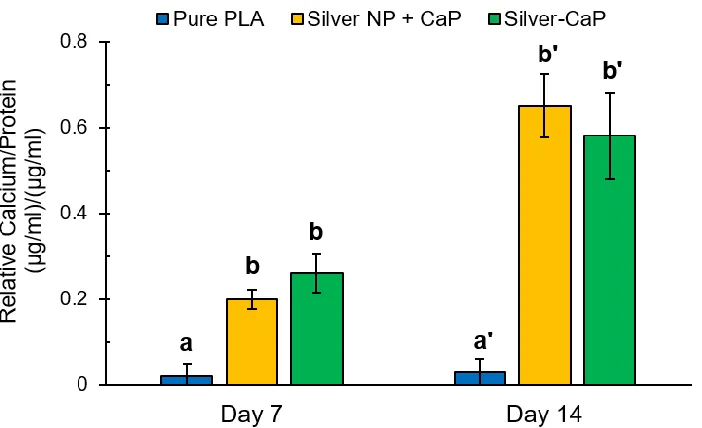
2.2.3.5. Osteogenic differentiation.
41 Figure 2. 17 hASC calcium accretion after 14 days of culture on a) PLA negative control, b) silver nanoparticles + CaP samples, c) silver-CaP loaded composite. The
degree of hASC mineralization was determined by Alizarin Red (labeled in red).
42 Figure 2. 18 Quantified calcium accretion normalized to BCA protein content. Different
letters indicate there is a significant difference between the samples (p < 0.05).
43 Figure 2. 19 mRNA expression in of osteogenic markers (a) Runx2 and (b) BMP2. The
mRNA expression normalized to the negative control PLA samples (p < 0.05).
44 nanoparticles + CaP directly loaded samples and silver-CaP loaded samples. The results suggest that the different silver loading methods in the PLA scaffolds at a concentration of 1 wt.% do not hinder osteogenic differentiation of hASC. These findings are consistent with previous reports.23
2.2.4. Conclusion.
45
3.
CHAPTER III A High Throughput Fabrication Method of
Silver Nanoparticles-Doped-Nanoclay Polymer Composite
with Synergistic Antibacterial Effect at the Interface
3.1.
Motivation
In the previous chapter, we found that loading of 1 wt.% silver into the polymer resulted
in composites that exhibited satisfactory antibacterial efficiency. However, for general
healthcare applications, the addition of 1 wt.% silver may cause a significant increase in
the material cost, which might limit potential applications.
Recently, investigators have reported that inclusion of certain submicron structures on
material surfaces significantly alters bacterial adhesion to the materials. In this chapter, we
develop and test an approach to load a low-cost additive, nanoclay, into polymer to alter
the sub-micron structures at the material surface, which we hypothesized would result in a
composite that exhibits significantly lower affinity for bacterial adhesion.
Additionally, we proposed a future study to apply this novel approach for bone tissue
engineering scaffold development. We believe that by creating micro- or nanostructures on
material surfaces; the developed composite may potentially mimic the natural bone surface,
potentially enhancing material biocompatibility and desired cell response.
46 3.1.1. Introduction:
There is increasing industrial demand for high-performance materials with multiple enhanced properties that can be created using minimal changes to industry standard equipment, processes and input cost.94 Due to the relatively low cost and commercial availability, nanoclay has been widely used to improve the modulus, tensile strength, barrier properties and thermal properties polymers.72, 95-100 It has been shown that loading
a small amount of nanoclay into polymer results in significantly enhanced material properties.101-103
For materials of potential use in medical or healthcare related industrial sectors, the antibacterial capability of the material is also of great interest. However, it has been shown that direct loading of nanoclay into polymer neither results in bacterial toxicity nor inhibits the growth of bacteria.104-106
Recently, investigators have shown that creation of certain micro- or nano-structures on material surfaces significantly altered their bacterial adhesion behavior.28-35 For example, for materials with surface structures at the micron scale, it was found that smaller size topologies decreased bacterial attachment.28, 30 At the nanoscale, bacterial biofilm formation has been observed to be more pronounced on material surfaces with a root-mean-square (RMS) roughness value of 10 nm compared to that of either 5 nm or 15 nm.36
47 cannot be easily applied to large-scale, low-cost industrial production without considerable changes in standard equipment or production processes.
Silver nanoparticles (silver NP) have also been extensively studied for antibacterial applications due to their wide-spectrum antibacterial activity.107-110 However, direct loading of silver NP into polymers often requires a high silver content to achieve a satisfactory antibacterial effect. For example, it was reported that to obtain 1-order (90%) decrease in bacterial number, at least 1 wt.% silver NP is required.108-109 This is a considerable problem when cost is a concern. Therefore, industrial application of the direct loading approach is very limited.
48 3.1.2. Materials and Experiments:
3.1.2.1. Materials.
Polylactic acid (PLA) grade 6202D (NatureWorks LLC, Minnetonka, MN), a biodegradable and biocompatible polymer, was used as the matrix material for the nanocomposite. Nanomer I.44P nanoclay, control silver nanoparticles, and aqueous silver nitrate solution (0.1 M, 99%) were obtained from Sigma–Aldrich, USA.
3.1.2.2. Silver NP-nanoclay production.
A two-step process was developed to fabricate the silver doped-nanoclay (silver NP-nanoclay): silver ion-exchange and in-situ thermal reduction. In the first step, 10 g nanoclay was added into 100 ml 0.1 M silver nitrate solution and stirred vigorously for 30 min. The solution was stirred overnight at 60 °C for silver ion-exchange. The resulting mixture was centrifuged at 5000 rpm then washed three times with distilled water. Obtained silver ion-exchanged-nanoclay was used immediately after drying. The in-situ thermal reduction of silver NP-nanoclay occurs simultaneously during the composite fabrication process due to the relatively high processing temperature.
3.1.2.3. Composite fabrication.
49 (Clinton, TN). The masterbatches were melt diluted with pure PLA in the meltblown unit inside-built screw extruder to obtain the final additive concentrations. During the fabrication process, polymer melts were blown by high-velocity hot air streams and attenuated by drag force to form fine fibrous self-bonding polymer composite meshes. Before fabrication, materials were dried overnight to remove absorbed water. Optimized fabrication parameters utilized in this study are provided in Table 3.1.
Table 3. 1 Optimized key fabrication parameters.
Optimized Fabrication Parameters
Die Temp.: 273 °C
Melt Temp.: 282 °C
Air Temp.: 254 °C
Air flow: 12 Psi
Throughput: 0.2 ghm
3.1.2.4. Composite characterizations.
50 During this test, the samples were not coated with any metals. An atomic force microscope (AFM; Bruker Dimension 3000) was used to visualize and quantify each sample’s surface roughness (root-mean-square roughness).
3.1.2.5. Antibacterial tests.
Two antibacterial tests, bacterial adhesion test, and material interface antibacterial test, were performed in this study against two bacterial strains: Gram-negative Escherichia coli and Gram-positive Staphylococcus aureus, individually. For both tests, sterilized disc specimens with an area of 0.95 cm2 were placed in 48-well plates, and pre-soaked in
phosphate-buffered saline (PBS) for 24 h. 1 ml bacterial suspension with an initial concentration of 106 CFU ml-1 was added to each well.
The bacterial adhesion test was modified from several previous reports 28, 37-38. Specifically, after 1-hour incubation, samples were gently rinsed three times with sterile PBS to remove unbound or loosely attached bacteria. Firmly attached bacteria were stained by immersing samples in SYTO® 9 (Thermo Fisher Scientific, Waltham, MA) solution following manufacturer’s protocol and observed using fluorescent microscopy (Leica DM5500B). For quantitative analysis of adherent bacteria, rinsed discs were placed in 1 ml PBS with 1% Trion X-100 added and vigorously vortexed for 5 min to remove attached bacteria. 28,
37-38 Subsequently, the 1 ml PBS samples were serially diluted and diluents of 100 ul were