A Modified Omnidirectional Bi-Conical Broad Band
Antenna for VHF and UHF Range
Abhishek Singh
M.Tech Scholar-DC
Deptt. of Electronics and Communication NIIST, RGPV Bhopal, M.P
Akhilesh Jain
Assistant Professor
Deptt. of Electronics and Communication NIIST, RGPV Bhopal, M.P
ABSTRACT
In the proposed design proposed a novel bi-conical antenna that is use for VHF as well as UHF range. The proposed antenna shows a wide band and cover VHF and UHF ranges whose frequencies is between 30 to above 310 MHz. The range of proposed design cover the television and radio communication range. Also shows the good result in terms of return loss that is (S-11) -52.27 dB as well as VSWR that is 1.02 and important parameter is percentage bandwidth is 142.85%. The proposed design shows good result as compared to other previous method’s results on the basis of basic of different antenna parameters such as VSWR, Return Loss and bandwidth
Keywords
Returen loss (S-11), VSWR, UHF and VHF ranges.
1.
INTRODUCTION
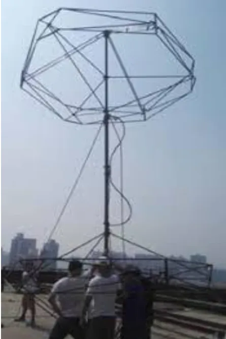
We In radio communication, an Omni directional antenna is a class of antenna which have an axis about which radio wave power is radiated symmetrically, and, upon that axis, is zero. This is different from an isotropic antenna, whose power is radiated symmetrically about any axis, having a spherical radiation pattern. Omni directional antennas oriented vertically are widely used for non directional antennas on the surface of the Earth because they radiate equally in all horizontal directions, while the power radiated drops off with elevation angle so little radio energy is aimed into the sky or down toward the earth and wasted. Omni directional antennas are widely used for radio broadcasting antennas, and in mobile devices that use radio such as cell phones, FM radios, walkie-talkies, cordless phones, GPS, as well as for base stations that communicate with mobile radios, such as police and taxi dispatchers and aircraft communications Several methods, such as Alford loop, left-handed loading loop, and horizontal dipoles printed around a dielectric cylindrical barrel, are utilized to produce horizontal polarization Omni directional radiation patterns. The image given below as figure 1 shows a real Horizontally Polarized Omni directional Antenna for VHF Applications. When we talk about the wearable antennas, they are in mobile radio communication for soldiers, emergency operators, and law-enforcement personnel. The demand for navigation systems for commercial and social utilization at sea, on land and in the air is on the rise. To ensure the safety of navigation for all seamen, tourists on boats and shipping owners from any distress and disasters at sea, the used of communication and positioning system is indispensable.
A key technology to achieve this goal is wearable electronics and small antennas. Hundreds scientific papers on wearable antennas have been published in the literature. Therefore, for the sake of completeness and clarity an analysis of the state of the art on wearable antenna should be limited to antennas for specific applications or a given frequency ranges. Usually
[image:1.595.317.540.263.597.2]wearable antennas are in mobile radio communication for soldiers, emergency operators, and law-enforcement personnel. Because of its almost global availability, the VHF and UHF maritime applications bands are utilized for the development of these antennas.
Fig 1 A Broadband Horizontally Polarized Omni directional Antenna for VHF Applications. [01]
10
2.
LITERATURE SURVEY
Zhang et.al [01] 2018 An antenna that is wideband with HP omni directional pattern in the azimuthal plane is been considered here. The deduction in the shape and size of the antenna is done by folded elements. There are 3 bowtie shaped dipoles which are fed by lines which are three-way parallel transmission power divider. The balun structure which is a slot line one is the reason for an increase in the broadband impedance matching. It realizes balanced-to-unbalanced transformation. The HP antenna covers a fractional impedance bandwidth of 24.7% (from 39 to 50 MHz). The operating band covers the steady omni directional radiation pattern with low gain variations. These types of omni directional antennas have the characteristics of low wind age, easy disassembly, lower cost and expense, and good performance. The two-element antenna array is been designed by a measurable gain of about 3.5 dBi across the whole operating band. The proposed HP loop antenna and the two-element array can be good candidates for the MBCS applications. Takacs et.al.[02] 2017 A dipole antenna which sustain a planar with dual-band Kapton supported for cube sat applications was projected. The antenna having a much less weight (mass<4g) is simple to incorporate into a cube sat as VHF/UHF antenna. Method of the design was presented with the importance of the guidelines given for a design. The electromagnetic simulation forecast better performances for input matching and energy radiation pattern. Sokpor et.al [06] 2016 The theory of ribbon monopole antenna, small in size is been shown here for UHF/VHF maritime applications. A LC-matching circuit was used to switch from UHF (420 MHz) to VHF (167 MHz) band, without degrading the presentation performance of the antenna. An aantenna radiates 50% - 60% of the energy fed to it (-3 to -2.2 dB). To calculate the approximation of antenna’s effectiveness, measurements were made by the Wheeler cap and in the reverberation chamber. The results of Simulation and measurement point out a fair agreement. Furthermore, the antenna exhibits the efficiency (>90%) in the UHF band and the VHF band. Gao et. al. [07] 2015 The literature survey consist of a log-periodic antenna which is balloon in shape. This antenna is dependent upon a strip-dipole and bowtie-dipole. When compared to bowtie-dipoles, the balloon antenna gives advantages like size is smaller, wide bandwidth, steady end-fire patterns and radiation efficiency and gain. The antenna prototype which is fabricated with aluminum foils and PVC balloons gave the radiation performances which are better than the proposed design and its potential of application in VHF-band wireless communication systems. A conformal log-periodic balloon antenna operating at the very high frequency (VHF) band is presented in this literature survey. Eight conformal bowtie-dipole components which are been cross fed by an information transferring line further joined to the surface balloon shaped as cylinder. The new one is been designed. The working bandwidth covers the megahertz from 60 to 233 with the voltage standing wave ratio (VSWR) radiation pattern of 5 dBi average gain. Chen et.al [14] 2011 The theory here explains about a very low-profile wideband VHF/UHF antenna which is built on a discone antenna which is having 3 major additions: the back hollow, the short-circuited structure, and the two-plate top structure. When they are joined together the VSWR bandwidth of the proposed antenna is widened and a prototype was been designed and tested. The result given is that the VSWR is less than 2.5 from 200 to 447 MHz, considered as a wide bandwidth of 76%. The height of the prototype is making it very low-profile. The radiation patterns on the horizontal plane are omni directional with an unevenness of less than 3 dB. The structure of the antenna
[image:2.595.331.522.121.262.2]presented in this letter has it’s extend to high and low frequency bands. Those results will be reported in our future publications.
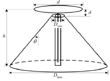
Fig. 2 Conventional discone antenna
Ding et.al [15] 2010 A GA is used here to optimize a VHF/UHF antenna and its qualities also are mentioned here. The diameter it covers is 1.9 cm and the height covered is 1.79 m, which includes a 1.47-m loaded wire monopole and a 0.32-m sleeve pedestal. Further talking about it, it is having a wide band which covers VHF and UHF band from 30 to 520 MHz with VSWR less than 2. When other ways of lossy loading are compared the result got was that this lossless loading way gives a higher horizon gain, which is greater than 0 dBi in working band. The effectiveness calculated of the matching network is found to be between 35% and 55%. Now we can use the designed antenna in vehicles, shipboard, and civil mobile communication.
3.
PROPOSED ANTENNA
In this presented work shows the Modified biconical antenna (MBCA) with disk cone designed. In this VHF-UHF range antenna use co-axial feeding technique for the enhancement of bandwidth of the proposed antenna Modified biconical antenna has become admired day by day the reason behind the high bandwidth and ease of manufacturing process. The proposed biconical antenna is designed for wide band range in Mega hertz frequency 54MHz to 550MHz where this frequency range accommodate in the various band in very high frequency range and ultra high frequency range spectrum and Radiate Wave. Modified biconical antenna (MBCA) have Gaining importance in the applications of Wireless communication devices radio frequencies (RF).
3.1
Modified Biconical antenna
other plane. The impedance of the feeding point of Biconical antenna is generally chosen to be 50Ω because most of the coaxial connectors have 50Ω impedance. The impedance of a Biconical antenna depends upon its conical geometry and impedance decreases with increase in conical geometry. In most of the Biconical antennas, the impedance varies between 50‐75Ω based on the cone angle.
3.2
Design Steps of Proposed Antenna
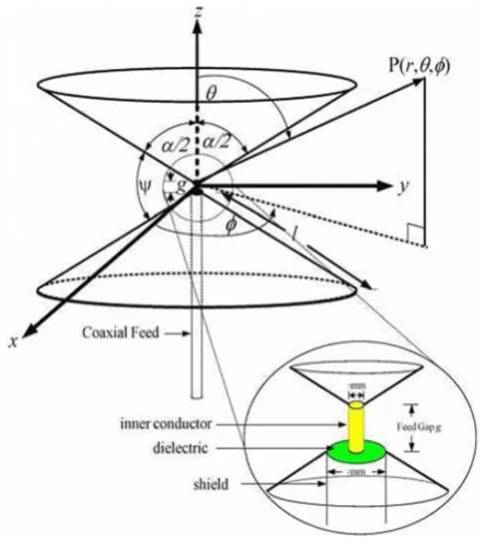
In the below figure 3 shows the figure of biconical antenna, in the biconical antenna contains two cones at particular angle that is α, and a gap between two cones that is knows as a Gap (G).
Where
: wavelength in free-space,
: Characteristic impedance of the antenna,
: Legendre polynomial of order n, (4)
: Complex auxiliary function of the real variable kl,
: spherical Hankel function of the 2ndorder
[image:3.595.309.545.95.681.2]The designing of cone antenna require the above mutation equation these are shown in above. In the below figure 4 shows the modified Biconical antenna that is design on CST microwave studio.
Fig. 3 Shows Bi-conical antenna
Table 1 Dimension of Proposed Modified biconical antenna
Cone Disk Cone
Cone diameter (D1) Out
800 mm Gap (G) 9mm
Length of cone (LC1)
750 mm Disk Cone diameter (DC1)
600 mm
Cone Radios (R1) out
400 mm Disk Cone radios (DCR1)
300 mm
Inner Radios Cone (rC)
8.315 Disk Cone length (DCL)
110 mm
(a)Diameter of Cone
(b) Gap Length
[image:3.595.53.275.430.677.2]12
4.
SIMULATION AND RESULT
The presented modified bi-conical with discone is design for mega hertz (MHz) range frequency range 50 MHz to above 300 MHz. This frequency range accommodate in various bands, it covers radio and television broadcasts as well as land mobile and maritime mobile communications. The modified bi-conical antenna is gaining importance due to its versatile applications in military as radio communication. Results of proposed Bi-conical antenna
4.1
S -11 Parameter
[image:4.595.316.545.74.342.2]In the below figure 6 shows parametric study of proposed modified bi-conical design shape. There are two parameters are analyzed, discone outer radios , gap (G) and out radios of cone. There are five outcome shows in the above results, first S11 (1), S11 (2) and S11 (3) up to S11(5) shows the different dimensions of between 80mm to 120mm. In the above analysis clearly show that higher value of the cone length get better return losses (S-11) shown in below tables 2
[image:4.595.317.547.78.204.2]Fig. 5.Shows the S – 11 Parameter of proposed design II
Fig. 6 VSWR Parameter of Octagon shape based patch antenna
In the above parametric study clearly see that the return loss (S-11) change dramatically. The highest return loss (S-11) is achieved at 157 MHz that is -52.27 dB with a large size wide bandwidth that is 142.85%. The bandwidth of proposed antenna is above 50% and 100% that why it is ultra wide band range (UWB).In the above Figure 5.4 shows the voltage standing wave ratio of proposed antenna 2. In the idea case VSWR in between 1 to 2.5. In the X axis shows the frequency range and Y axis shows the VSWR range. The output of proposed antenna 2.5 in case VSWR overall result is good in overall bands, the VSWR at different frequencies 49.96MHz to 100MHz are between 2.5 to 1.5, in the UHF range 118 MHz to 300 MHz 1.09. In all the cover range by proposed antenna VSWR under 2.5 that is shows good result
4.2
Gain (G)
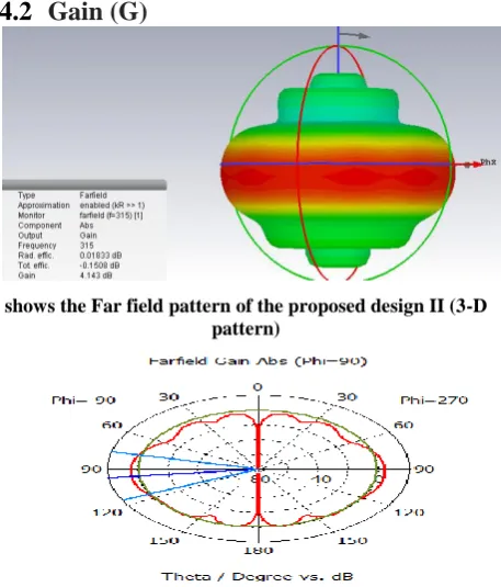
shows the Far field pattern of the proposed design II (3-D pattern)
Fig. 7 shows the Far field pattern of the proposed design II (2-D pattern)
In the above shows the different design and its result now one of the important task of thesis work that is compare calculated results with other methods. That is shown below in table 2. This table shows comparison on the basic parameters of antenna. These parameters are frequency range return losses (S-11) and number of bands
Table 2 Shows Result Comparison of proposed method with
Title Antenna
Shapes
Rang e
MHz
S – 11 / VSWR Band Width
Proposed Design
Modified Bi-Conical antenna
40-300+
(S-11 ) 157= -52.27
(VSWR)118 -300+ =1.09,
50.7-99.6 = 1.5
142.85 %
(249.04 MHz )
A Broadband Horizontall y Polarized Omni directional Antenna
for VHF
Applicatio n
Bow-Tie Shaped
38-52 VSWR
38-52 = 1.6
14 MHz
(31%)
VHF/UHF Kapton supported antenna for cubesat application
Cross Dipole 100-550
Return Loss (S-11)
-21 dB
[image:4.595.54.291.286.427.2] [image:4.595.54.291.287.581.2]5.
CONCLUSION
This presented work shows the design of modified bi-conical antenna with dis-cone. The proposed design shows good result as compared to other previous method’s results on the basis of basic of different antenna parameters such as VSWR, Return Loss and bandwidth. The proposed antenna shows a wide band and cover VHF and UHF ranges whose frequencies is between 30 to above 310 MHz. The range of proposed design cover the television and radio communication range. Also shows the good result in terms of return loss that is (S-11) -52.27 dB as well as VSWR that is 1.02 and important parameter is percentage bandwidth is 142.85%. [21]
6.
REFERENCES
[1] Bowman, Zhang, Zhi-Ya, Yarui Zhao, Shaoli Zuo, Long Yang, Luyang Ji, and Guang Fu. "A Broadband Horizontally Polarized Omni directional Antenna for VHF Application." IEEE Transactions on Antennas and Propagation (2018).
[2] Takacs, A., S. Charlot, P. Calmon, and D. Dragomirescu. "VHF/UHF Kapton supported antenna for cubesat applications." In Antennas and Propagation & USNC/URSI National Radio Science Meeting, 2017 IEEE International Symposium on, pp. 2485-2486. IEEE, 2017.
[3] Shih, Ting-Yen, and Nader Behdad. "Design of vehicle-mounted, compact VHF antennas using characteristic mode theory." In Antennas and Propagation (EUCAP), 2017 11th European Conference on, pp. 1765-1768. IEEE, 2017.
[4] Giacomini, A., V. Schirosi, F. Saccardi, F. Rossi, N. J. G. Fonseca, P. de Maagt, and L. J. Foged. "Measurements of low gain antennas at VHF frequencies for space-based AIS applications." In Antennas and Propagation (EUCAP), 2017 11th European Conference on, pp. 1299-1302. IEEE, 2017.
[5] Presse, Anthony, Jean Marie Floc'h, and Anne Claude Tarrot. "Flexible UHF/VHF Vivaldi antenna for broadband and gas balloon applications." In Radar Conference (EURAD), 2017 European, pp. 370-373. IEEE, 2017.
[6] Sokpor, A. S., M. Mantash, A. C. Tarot, and J. M. Floch. "Efficient small switchable ribbon monopole antenna for VHF/UHF maritime applications." In Antennas and Propagation (EuCAP), 2016 10th European Conference on, pp. 1-4. IEEE, 2016.
[7] Gao, Xiang, Zhongxiang Shen, and Changzhou Hua. "Conformal VHF log-periodic balloon antenna." IEEE Transactions on Antennas and Propagation 63, no. 6 (2015): 2756-2761.
[8] Shih, Ting-Yen, and Nader Behdad. "Design of platform-mounted HF/VHF antennas using the characteristic modes theory." In Antenna Technology (iWAT), 2015 International Workshop on, pp. 84-86. IEEE, 2015. [9] Rhee, Chang Yong, Jea Hak Kim, Woo Jae Jung,
Taejoon Park, Byungje Lee, and Chang Won Jung. "Frequency-reconfigurable antenna for broadband airborne applications." IEEE Antennas and Wireless Propagation Letters 13 (2014): 189-192.
[10]Weily, Andrew R., Ken W. Smart, and Trevor S. Bird. "Dual-band VHF/UHF smartphone antenna for mobile digital television." In Antenna Technology:" Small
Antennas, Novel EM Structures and Materials, and Applications"(iWAT), 2014 International Workshop on, pp. 228-231. IEEE, 2014.
[11] Mueller, Rainer, and Ralf Lorch. "Application of modern DOA algorithms to an adcock array antenna." In Antennas and Propagation (EuCAP), 2014 8th European Conference on, pp. 2215-2218. IEEE, 2014. [12] Foged, L. J., R. Morbidini, L. M. Tancioni, A.
Giacomini, and John Estrada. "A wide bandwidth dual polarized VHF band horn for antenna measurement applications." In Antennas and Propagation Society International Symposium (APSURSI), 2013 IEEE, pp. 2161-2162. IEEE, 2013.
[13] Yang, Guo-Min. "A compact microstrip ultra-wideband (UWB) antenna for VHF/UHF band applications." In Antennas and Propagation Society International Symposium (APSURSI), 2013 IEEE, pp. 11-12. IEEE, 2013.
[14] Chen, Aixin, Tiehua Jiang, Zhizhang Chen, Donglin Su, Wenxuan Wei, and Yanjun Zhang. "A wideband VHF/UHF discone-based antenna." IEEE Antennas and wireless propagation letters 10 (2011): 450-453.
[15] Pranay Yadav and Shachi Sharma, “Double Element Ultra Wideband Monopole Radiating Antenna Array with Coplanar-Ground Plane”, International Conference on Electrical, Electronics, Computers, Communication, Mechanical and Computing (EECCMC), 26-28 (Jan 2018).
[16] Pranay Yadav, and Shachi Sharma, “ SAR Images Target Detection based on Fuzzy C-Mean with ROI Detection”, International Conference on Electrical, Electronics, Computers, Communication, Mechanical and Computing (EECCMC), IEEE Conference 2018 (Accepted). 26-28 (Jan 2018).
[17] Shachi Sharma and Pranay Yadav, “SAR Image Object Detection Based on Fuzzy C –means with ROI detection
”, International Conference on Electrical, Electronics, Computers, Communication, Mechanical and Computing (EECCMC), 26-28 Jan 2018.
[18] Pranay Yadav – “Color Image Noise Removal by Modified Adaptive Threshold Median Filter for RVIN” in National Institution of Technology (NIT - Shilog) Confrence date 28 – 29 Jan. 2015.
[19] Pranay Yadav and Parool Singh – “Color Impulse Noise Removal by Modified Unsymmetric Trimmed Median Mean Filter for FVIN” in PARK College of Engineering and Tekhnology, Coimbatore-641659, Tamilnadu, India. IEEE International Conference on Computational Intelligence and Computing. 17 – 19 Dec. 2014 [20] Shachi Sharma and Pranay Yadav “Removal of Fixed
Valued Impulse Noise by Improved Trimmed Mean Median Filter” in PARK College of Engineering and Tekhnology, Coimbatore-641659, Tamilnadu, India. International Conference on Computational Intelligence and Computing.17-19 Dec 2014.